EP0106569A2 - Device for transferring particulate material - Google Patents
Device for transferring particulate material Download PDFInfo
- Publication number
- EP0106569A2 EP0106569A2 EP83305600A EP83305600A EP0106569A2 EP 0106569 A2 EP0106569 A2 EP 0106569A2 EP 83305600 A EP83305600 A EP 83305600A EP 83305600 A EP83305600 A EP 83305600A EP 0106569 A2 EP0106569 A2 EP 0106569A2
- Authority
- EP
- European Patent Office
- Prior art keywords
- refill container
- hopper
- receiving orifice
- aperture
- chute
- Prior art date
- Legal status (The legal status is an assumption and is not a legal conclusion. Google has not performed a legal analysis and makes no representation as to the accuracy of the status listed.)
- Granted
Links
- 239000011236 particulate material Substances 0.000 title claims abstract description 6
- 238000007789 sealing Methods 0.000 claims abstract description 11
- 239000012528 membrane Substances 0.000 claims abstract description 10
- 239000000463 material Substances 0.000 claims abstract description 9
- 238000004140 cleaning Methods 0.000 description 5
- 230000003287 optical effect Effects 0.000 description 5
- 239000002245 particle Substances 0.000 description 5
- 239000000843 powder Substances 0.000 description 5
- 108091008695 photoreceptors Proteins 0.000 description 4
- 238000003384 imaging method Methods 0.000 description 3
- 239000004033 plastic Substances 0.000 description 3
- 229920003023 plastic Polymers 0.000 description 3
- 230000005684 electric field Effects 0.000 description 2
- 230000001360 synchronised effect Effects 0.000 description 2
- 230000003749 cleanliness Effects 0.000 description 1
- 238000011109 contamination Methods 0.000 description 1
- 229920002457 flexible plastic Polymers 0.000 description 1
- 239000006260 foam Substances 0.000 description 1
- 229920001821 foam rubber Polymers 0.000 description 1
- 238000003780 insertion Methods 0.000 description 1
- 230000037431 insertion Effects 0.000 description 1
- 239000000203 mixture Substances 0.000 description 1
- 238000000465 moulding Methods 0.000 description 1
Images


Classifications
-
- G—PHYSICS
- G03—PHOTOGRAPHY; CINEMATOGRAPHY; ANALOGOUS TECHNIQUES USING WAVES OTHER THAN OPTICAL WAVES; ELECTROGRAPHY; HOLOGRAPHY
- G03G—ELECTROGRAPHY; ELECTROPHOTOGRAPHY; MAGNETOGRAPHY
- G03G15/00—Apparatus for electrographic processes using a charge pattern
- G03G15/06—Apparatus for electrographic processes using a charge pattern for developing
- G03G15/08—Apparatus for electrographic processes using a charge pattern for developing using a solid developer, e.g. powder developer
- G03G15/0822—Arrangements for preparing, mixing, supplying or dispensing developer
- G03G15/0877—Arrangements for metering and dispensing developer from a developer cartridge into the development unit
- G03G15/0881—Sealing of developer cartridges
- G03G15/0884—Sealing of developer cartridges by a sealing film to be ruptured or cut
Definitions
- This invention relates to a device for transferring particulate material from a refill container into a hopper for the material.
- the invention is particularly concerned with such a device in which the hopper includes a substantially horizontal filling aperture closable by a lid.
- a typical toner loading arrangement is to supply the toner powder in a refill container such as a carton or plastic bottle, and to load this into a hopper in the copying machine after removal of a hinged or removable lid. The toner is then simply tipped from the refill container into the hopper. Such an arrangement gives rise to the escape of toner, firstly by an initial fall of powder into the hopper which creates clouds of the powder, and secondly by toner powder which falls from the refill container as it is introduced to, and removed from, the vicinity of the hopper.
- the present invention is intended to overcome this problem of how to carry out a clean loading operation, and to provide a device of the kind described which is characterised in that in response to opening the lid, a hinged chute member sealingly engaging said aperture and containing a receiving orifice for said refill container is spring urged out of the aperture so that the receiving orifice is inclined to the horizontal whereby the refill container does not have to be completely inverted in order to introduce the exit orifice of the refill container into the receiving orifice of the chute member, and whereby the refill container, when engaged in the receiving orifice, may be inverted to empty the material into the hopper.
- the dispensing container includes means to perforate a sealing membrane of the refill container.
- FIG. 1 there is shown a xerographic copying machine incorporating the present invention.
- the machine includes a photoreceptor drum 1 mounted for rotation (in the clockwise direction as seen in Figure 1) to carry the photoconductive imaging surface of the drum sequentially through a series of xerographic processing stations: a charging station 2, an imaging station 3, a development station 4, a transfer station 5, and a cleaning station 6.
- the charging station 2 comprises a corotron which deposits a uniform electrostatic charge on the photoreceptor.
- a document to be reproduced is positioned on a platen 13 and scanned by means of a moving optical scanning system to produce a flowing light image on the drum at 3.
- the optical image selectively discharges the photoconductor in image configuration, whereby an electrostatic latent image of the object is laid down on the drum surface.
- the electrostatic latent image is developed into visible form by bringing into contact with it toner particles which deposit on the charged areas of the photoreceptor.
- Cut sheets of paper are moved into the transfer station 5 in synchronous relation with the image on the drum surface and the developed image is transferred to a copy sheet at the transfer station 5, where a transfer corotron 7 provides an electric field to assist in the transfer of the toner particles thereto.
- the copy sheet is then stripped from the drum 1, the detachment being assisted by the electric field provided by an a.c. de-tack corotron 8.
- the copy sheet carrying the developed image is then carried by a transport belt system 9 to a fusing station 10.
- the optical image at imaging station 3 is formed by optical system 12.
- a document (not shown) to be copied is placed on platen 13, and is illuminated by a lamp 14 that is mounted on a scanning carriage 15 which also carries a mirror 16.
- Mirror 16 is the full-rate scanning mirror of a full and half-rate scanning system.
- the full-rate mirror 16 reflects an image of a strip of the document to be copied onto the half-rate scanning mirror 17.
- the image is focussed by a lens 18 onto the drum 1, being deflected by a fixed mirror 19.
- the full-rate mirror 16 and lamp 14 are moved across the machine at a constant speed, while at the same time the half-rate mirrors 17 are moved in the same direction at half that speed.
- the mirrors are in the position shown in a broken outline at the left hand side of Figure 1.
- a magnetic brush developer system 20 develops the electrostatic latent image.
- Toner is dispensed from a hopper 21 by means of a rotating foam roll dispenser 22, into developer housing 23.
- Housing 23 contains a two-component developer mixture comprising a magnetically attractable carrier and the toner, which is brought into developing engagement with drum 1 by a two-roller magnetic brush developing arrangement 24.
- the developed image is transferred, at transfer station 5, from the drum to a sheet of copy paper (not shown) which is delivered into contact with the drum by means of a paper supply system 25.
- Paper copy sheets are stored in two paper trays, an upper, main tray 26 and a lower, auxiliary tray 27.
- the top sheet of paper in either one of the trays is brought, as required, into feeding engagement with a common, fixed position, sheet separator/feeder 28.
- Sheet feeder 28 feeds sheets around curved guide 29 for registration at a registration point 30. Once registered, the sheet is fed into contact with the drum in synchronous relation to the image so as to receive the image at transfer station 5.
- the copy sheet carrying the transferred image is transported, by means of vacuum transport belt 9, to fuser 10, which is a heated roll fuser.
- the image is fixed to the copy sheet by the heat and pressure in the nip between the two rolls of the fuser.
- the final copy is fed by the fuser rolls along output guides 31 into catch tray 32, which is suitably an offsetting catch tray, via output nip rolls 31 a.
- a housing 33 forms with the drum 1 an enclosed cavity, within which is mounted a doctor blade 34. Doctor blade 34 scrapes residual toner particles off the drum, and the scraped-off particles then fall into the bottom of the housing, from where they are removed by an auger 35.
- the device of the invention is a clip-in fit to the horizontal aperture which forms the mouth of the toner hopper 2L
- the device consists of five main parts, which may suitably be plastics mouldings, four of which are as shown in Figures 3 to 5, and the fifth of which is either one of the two inserts shown in Figures 6 and 7.
- the device includes a chute 41, two end pieces 42 ( Figure 2) and a lid 43.
- the chute 41 as most clearly seen in Figure 5, has end walls 44 and a partially cylindrical curved surface 45.
- Each end wall 44 carries, inside the chute, a rib 46 which extends parallel with the upper rim 47 of the chute, for receiving either one of the inserts shown in Figures 6 and 7.
- the chute is arranged for pivotal movement by means of pivot pins 48 extending outwardly from the corners of the end walls 44 remote from the curved surface 45, the pivot pins being ;ubstantially on the cylindrical axis of the surface 45.
- the pivot pins 48 are )ivotally engaged in bearings 49 formed in the end pieces 42 ( Figure 2).
- the end pieces 42, supporting the chute 41, are secured into the top of the hopper 21 by means of resilient catch portions 50 of the end pieces 42 which engage a ridge 51 in the left hand wall of the hopper 21 (as viewed in Figure 2), as well as by spring members 52.
- Each of the spring members 52 has at least one coil which is supported by passing around a peg 53 formed on the end piece 42.
- the spring 52 is shaped so as to have a hook portion 54 at one end which engages the end wall 44 of the chute 41, and a substantially straight portion 55 at the other end which pushes against the right hand wall of the toner hopper 2L
- the end walls 44 of chute 41 are slidable between end pieces 42, and the springs 52 urge the chute in the clockwise direction (as seen in Figures 2 to 4).
- Sealing strips 56 such as brush seals, are carried on the inside surfaces of the end pieces 42 (as indicated by the broken outline in figure 2).
- the chute 41 is normally held in the position shown in Figures 2 and 3, against the force of spring 52, by means of the lid 43 which also acts as a sealing closure for the hopper 2L Lid 43 is pivotted by means of pivot pins 57 formed on its. right hand edge (as viewed in Figure 2) in bearings formed in the end pieces 42. Latching members 58 on the left hand edge of the lid engage a ridge 59 formed at the top of the hopper 2L
- a sealing strip 60 such as a brush seal, is mounted on the inside left hand wall of hopper 21 to provide a seal between that wall of the hopper and the curved surface 45 of the chute 41, regardless of the position of chute 4L
- the insert 61 shown in Figure 6 may be fitted into chute 41 by sliding channels 62 of insert 61 over the ribs 46.
- a sealing strip 63 around the three sides of the rim 47 of chute 41, and a sealing strip 64 along the remaining edge of insert 61, provide a complete seal between the insert 61 and the chute 41, and therefore effectively form a complete seal between the insert 61. and the hopper 21.
- the top face of insert 61 has a circular aperture 65 which is su " rounded by a foam rubber seal 66.
- the aperture 65 and seal 66 are shaped to receive the neck of a toner refill container. in the form of a disposable plastics bottle, the neck of which fits through the aperture 65, and the shoulders of which form a closure with seal 66.
- the sequence is as follows.
- the lid 43 is opened, and chute 41 pops up to the position shown in Figure 4.
- the cap or seal of the refill bottle is removed and the neck of the bottle brought up to the aperture 65 with the bottle in a substantially horizontal position.
- the body of the bottle is then moved upwards and the neck inserted into the aperture 65, until the shoulders of the bottle form a closure with the seal 66.
- the bottle is then raised to a substantially vertical position (by hinging the chute back into the hopper 21 against the force of springs 52) so as to dump the toner into the hopper.
- Once empty, the bottle is removed after allowing the chute 41 to pop out again to the 45° position.
- the lid 43 is then closed to seal the hopper.
- the insert 67 shown in Figure 7 is used.
- the insert 67 -consists of three walls which fit around the inside of chute 41, the two end. walls 68 of insert 67 having slots 69 formed in them for engagement over the ribs 46 of chute 41.
- the upper edges of the . walls of insert 67 are sharply serrated as shown to form cutting edges.
- the cutting edges, when the insert 67 is in place, are spaced from the inside walls of chute 41 by a distance which is sufficient to permit the insertion of the top of a refill carton of the kind indicated diagrammatically in Figure 4.
- the carton 70 is of cuboidal form having four sides and a bottom formed of, for example, cardboard.
- a suitable sealed container for the toner material for example of flexible plastics material, is secured inside the carton, and is sealed by means of a taut membrane set inside the open top of the carton, as indicated in broken outline at 71 in Figure 4.
- the lid 43 of the device is opened as before, allowing the chute 41 to pop up to the position in Figure 4.
- the carton top is introduced directly into the open top of chute 41, with the cutting edges of insert 67 close to, but not touching, the membrane 71.
- the carton is then inverted (i.e. the chute 41 pushed down against the spring 52) and pushed firmly downwards so that the cutting edges of insert 67 cut the membrane along three sides close to the inside wall of the carton, allowing the membrane to hinge downwards about its remaining edge and dump the toner into the hopper.
- the chute 41 is allowed to pop up again to the 45 0 position and the carton is withdrawn.
- the lid 43 is then closed.
- the toner loading operation is carried out in such a way that as the toner is dumped from the refill container, there is a substantially sealed closure between the refill container and the hopper, leading to a virtually clean loading operation.
Abstract
Description
- This invention relates to a device for transferring particulate material from a refill container into a hopper for the material. The invention is particularly concerned with such a device in which the hopper includes a substantially horizontal filling aperture closable by a lid.
- In many machines which consume particulate material, there arises the problem of how to reload the machine with the material without spillage or wastage. This problem arises particularly with xerographic copying machines which use a dry particulate material as their toner. Such toner is a strongly pigmented, finely-divided powder which needs careful handling to avoid contamination of the machine and soiling of the operator's clothing and hands. A typical toner loading arrangement is to supply the toner powder in a refill container such as a carton or plastic bottle, and to load this into a hopper in the copying machine after removal of a hinged or removable lid. The toner is then simply tipped from the refill container into the hopper. Such an arrangement gives rise to the escape of toner, firstly by an initial fall of powder into the hopper which creates clouds of the powder, and secondly by toner powder which falls from the refill container as it is introduced to, and removed from, the vicinity of the hopper.
- The present invention is intended to overcome this problem of how to carry out a clean loading operation, and to provide a device of the kind described which is characterised in that in response to opening the lid, a hinged chute member sealingly engaging said aperture and containing a receiving orifice for said refill container is spring urged out of the aperture so that the receiving orifice is inclined to the horizontal whereby the refill container does not have to be completely inverted in order to introduce the exit orifice of the refill container into the receiving orifice of the chute member, and whereby the refill container, when engaged in the receiving orifice, may be inverted to empty the material into the hopper.
- Th,e fact that the refill container does not have to be completely . i inverted as it is introduced into, and withdrawn from, the receiving orifice considerably improves the cleanliness of the transfer operation. A further improvement is provided by a preferred embodiment of the invention, wherein the dispensing container includes means to perforate a sealing membrane of the refill container.
- A device in accordance with the invention will now be described, by way of example, as applied to the toner loading arrangement of a xerographic copying machine, with reference to the accompanying drawings in which: -
- Figure 1 is a diagramatic cross-sectional view of a xerographic copying machine incorporating the present invention;
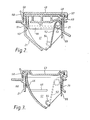
- Figure 2 is a cross-sectional view of the device of the invention, taken at one end, with the device in its 'closed' position;
- Figure 3 is a cross-sectional view of the device of the invention, taken in the middle, with the device in its 'closed' position;
- Figure 4 is a cross-sectional view corresponding with Figure 3, but with the device in its 'open' position;
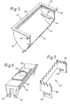
- Figure 5 is a perspective view of a chute forming part of the device;
- Figure 6 is a perspective view of a bottle receiver which fits into the chute of Figure 5; and
- Figure 7 is a perspective view of a perforator which fits into the chute of Figure 5 as an alternative to the bottle receiver of Figure 6.
- Referring first to Figure 1 there is shown a xerographic copying machine incorporating the present invention. The machine includes a photoreceptor drum 1 mounted for rotation (in the clockwise direction as seen in Figure 1) to carry the photoconductive imaging surface of the drum sequentially through a series of xerographic processing stations: a
charging station 2, animaging station 3, adevelopment station 4, atransfer station 5, and acleaning station 6. - The
charging station 2 comprises a corotron which deposits a uniform electrostatic charge on the photoreceptor. A document to be reproduced is positioned on aplaten 13 and scanned by means of a moving optical scanning system to produce a flowing light image on the drum at 3. The optical image selectively discharges the photoconductor in image configuration, whereby an electrostatic latent image of the object is laid down on the drum surface. At thedevelopment station 4,. the electrostatic latent image is developed into visible form by bringing into contact with it toner particles which deposit on the charged areas of the photoreceptor. Cut sheets of paper are moved into thetransfer station 5 in synchronous relation with the image on the drum surface and the developed image is transferred to a copy sheet at thetransfer station 5, where atransfer corotron 7 provides an electric field to assist in the transfer of the toner particles thereto. The copy sheet is then stripped from the drum 1, the detachment being assisted by the electric field provided by an a.c. de-tack corotron 8. The copy sheet carrying the developed image is then carried by atransport belt system 9 to afusing station 10. - After transfer of the developed image from the drum, some toner particles usually remain on the drum, and these are removed at the
cleaning station 6. After cleaning, any electrostatic charges remaining on the drum are removed by an a.c. erase corotron 11. The photoreceptor is then ready to be charged again by the chargingcorotron 2, as the first step in the next copy cycle. - The optical image at
imaging station 3 is formed byoptical system 12. A document (not shown) to be copied is placed onplaten 13, and is illuminated by alamp 14 that is mounted on a scanning carriage 15 which also carries amirror 16. Mirror 16 is the full-rate scanning mirror of a full and half-rate scanning system. The full-rate mirror 16 reflects an image of a strip of the document to be copied onto the half-rate scanning mirror 17. The image is focussed by alens 18 onto the drum 1, being deflected by afixed mirror 19. In operation, the full-rate mirror 16 andlamp 14 are moved across the machine at a constant speed, while at the same time the half-rate mirrors 17 are moved in the same direction at half that speed. At the end of a scan, the mirrors are in the position shown in a broken outline at the left hand side of Figure 1. These movements of the mirrors maintain a constant optical path length, so as to maintain the image on the drum in sharp focus throughout the scan. - At the
development station 4, a magneticbrush developer system 20 develops the electrostatic latent image. Toner is dispensed from ahopper 21 by means of a rotatingfoam roll dispenser 22, intodeveloper housing 23.Housing 23 contains a two-component developer mixture comprising a magnetically attractable carrier and the toner, which is brought into developing engagement with drum 1 by a two-roller magneticbrush developing arrangement 24. - The developed image is transferred, at
transfer station 5, from the drum to a sheet of copy paper (not shown) which is delivered into contact with the drum by means of apaper supply system 25. Paper copy sheets are stored in two paper trays, an upper,main tray 26 and a lower,auxiliary tray 27. The top sheet of paper in either one of the trays is brought, as required, into feeding engagement with a common, fixed position, sheet separator/feeder 28. Sheet feeder 28 feeds sheets aroundcurved guide 29 for registration at aregistration point 30. Once registered, the sheet is fed into contact with the drum in synchronous relation to the image so as to receive the image attransfer station 5. - The copy sheet carrying the transferred image is transported, by means of
vacuum transport belt 9, to fuser 10, which is a heated roll fuser. The image is fixed to the copy sheet by the heat and pressure in the nip between the two rolls of the fuser. The final copy is fed by the fuser rolls alongoutput guides 31 intocatch tray 32, which is suitably an offsetting catch tray, viaoutput nip rolls 31 a. - After transfer of the developed image from the drum to the copy sheet, the drum surface is cleaned at
cleaning station 6. At the cleaning station, ahousing 33 forms with the drum 1 an enclosed cavity, within which is mounted adoctor blade 34.Doctor blade 34 scrapes residual toner particles off the drum, and the scraped-off particles then fall into the bottom of the housing, from where they are removed by an auger 35. - Referring now to Figures 3 to 7, the device of the invention is a clip-in fit to the horizontal aperture which forms the mouth of the toner hopper 2L The device consists of five main parts, which may suitably be plastics mouldings, four of which are as shown in Figures 3 to 5, and the fifth of which is either one of the two inserts shown in Figures 6 and 7.
- As shown in Figures 3 to 5, the device includes a
chute 41, two end pieces 42 (Figure 2) and alid 43. Thechute 41, as most clearly seen in Figure 5, hasend walls 44 and a partially cylindricalcurved surface 45. Eachend wall 44 carries, inside the chute, arib 46 which extends parallel with theupper rim 47 of the chute, for receiving either one of the inserts shown in Figures 6 and 7. The chute is arranged for pivotal movement by means ofpivot pins 48 extending outwardly from the corners of theend walls 44 remote from thecurved surface 45, the pivot pins being ;ubstantially on the cylindrical axis of thesurface 45. Thepivot pins 48 are )ivotally engaged inbearings 49 formed in the end pieces 42 (Figure 2). - The
end pieces 42, supporting thechute 41, are secured into the top of thehopper 21 by means ofresilient catch portions 50 of theend pieces 42 which engage aridge 51 in the left hand wall of the hopper 21 (as viewed in Figure 2), as well as byspring members 52. Each of thespring members 52 has at least one coil which is supported by passing around apeg 53 formed on theend piece 42. Thespring 52 is shaped so as to have ahook portion 54 at one end which engages theend wall 44 of thechute 41, and a substantiallystraight portion 55 at the other end which pushes against the right hand wall of the toner hopper 2L - The
end walls 44 ofchute 41 are slidable betweenend pieces 42, and thesprings 52 urge the chute in the clockwise direction (as seen in Figures 2 to 4). Sealing strips 56, such as brush seals, are carried on the inside surfaces of the end pieces 42 (as indicated by the broken outline in figure 2). - The
chute 41 is normally held in the position shown in Figures 2 and 3, against the force ofspring 52, by means of thelid 43 which also acts as a sealing closure for thehopper 2L Lid 43 is pivotted by means of pivot pins 57 formed on its. right hand edge (as viewed in Figure 2) in bearings formed in theend pieces 42. Latchingmembers 58 on the left hand edge of the lid engage aridge 59 formed at the top of the hopper 2L - When the
lid 43 is undone, it may be pivotted through more than 180°, to take up a position like that shown in Figure 4, at the same time allowing thechute 41 to pop out until itsupper rim 47 is inclined at about 450 to the horizontal. A sealingstrip 60, such as a brush seal, is mounted on the inside left hand wall ofhopper 21 to provide a seal between that wall of the hopper and thecurved surface 45 of thechute 41, regardless of the position of chute 4L - Referring now to Figure 5 and 6, the
insert 61 shown in Figure 6 may be fitted intochute 41 by slidingchannels 62 ofinsert 61 over theribs 46. A sealingstrip 63 around the three sides of therim 47 ofchute 41, and a sealingstrip 64 along the remaining edge ofinsert 61, provide a complete seal between theinsert 61 and thechute 41, and therefore effectively form a complete seal between theinsert 61. and thehopper 21. The top face ofinsert 61 has acircular aperture 65 which is su"rounded by afoam rubber seal 66. Theaperture 65 andseal 66 are shaped to receive the neck of a toner refill container. in the form of a disposable plastics bottle, the neck of which fits through theaperture 65, and the shoulders of which form a closure withseal 66. In order to reload the hopper from a refill bottle, therefore, the sequence is as follows. Thelid 43 is opened, andchute 41 pops up to the position shown in Figure 4. The cap or seal of the refill bottle is removed and the neck of the bottle brought up to theaperture 65 with the bottle in a substantially horizontal position. The body of the bottle is then moved upwards and the neck inserted into theaperture 65, until the shoulders of the bottle form a closure with theseal 66. The bottle is then raised to a substantially vertical position (by hinging the chute back into thehopper 21 against the force of springs 52) so as to dump the toner into the hopper. Once empty, the bottle is removed after allowing thechute 41 to pop out again to the 45° position. Thelid 43 is then closed to seal the hopper. - In an alternative embodiment of the invention, the
insert 67 shown in Figure 7 is used. The insert 67 -consists of three walls which fit around the inside ofchute 41, the two end.walls 68 ofinsert 67 havingslots 69 formed in them for engagement over theribs 46 ofchute 41. The upper edges of the . walls ofinsert 67 are sharply serrated as shown to form cutting edges. The cutting edges, when theinsert 67 is in place, are spaced from the inside walls ofchute 41 by a distance which is sufficient to permit the insertion of the top of a refill carton of the kind indicated diagrammatically in Figure 4. Thecarton 70 is of cuboidal form having four sides and a bottom formed of, for example, cardboard. A suitable sealed container for the toner material, for example of flexible plastics material, is secured inside the carton, and is sealed by means of a taut membrane set inside the open top of the carton, as indicated in broken outline at 71 in Figure 4. - In order to load the toner from such a refill carton, the
lid 43 of the device is opened as before, allowing thechute 41 to pop up to the position in Figure 4. The carton top is introduced directly into the open top ofchute 41, with the cutting edges ofinsert 67 close to, but not touching, themembrane 71. The carton is then inverted (i.e. thechute 41 pushed down against the spring 52) and pushed firmly downwards so that the cutting edges ofinsert 67 cut the membrane along three sides close to the inside wall of the carton, allowing the membrane to hinge downwards about its remaining edge and dump the toner into the hopper. In order to remove the empty carton, thechute 41 is allowed to pop up again to the 450 position and the carton is withdrawn. Thelid 43 is then closed. - As will be appreciated from the foregoing, the toner loading operation is carried out in such a way that as the toner is dumped from the refill container, there is a substantially sealed closure between the refill container and the hopper, leading to a virtually clean loading operation.
Claims (4)
Applications Claiming Priority (2)
| Application Number | Priority Date | Filing Date | Title |
|---|---|---|---|
| GB8226824 | 1982-09-21 | ||
| GB8226824 | 1982-09-21 |
Publications (3)
| Publication Number | Publication Date |
|---|---|
| EP0106569A2 true EP0106569A2 (en) | 1984-04-25 |
| EP0106569A3 EP0106569A3 (en) | 1985-04-03 |
| EP0106569B1 EP0106569B1 (en) | 1987-11-04 |
Family
ID=10533059
Family Applications (1)
| Application Number | Title | Priority Date | Filing Date |
|---|---|---|---|
| EP83305600A Expired EP0106569B1 (en) | 1982-09-21 | 1983-09-21 | Device for transferring particulate material |
Country Status (11)
| Country | Link |
|---|---|
| US (1) | US4519693A (en) |
| EP (1) | EP0106569B1 (en) |
| JP (1) | JPS5981664A (en) |
| CA (1) | CA1203841A (en) |
| DE (1) | DE3374353D1 (en) |
| DK (1) | DK418883A (en) |
| EG (1) | EG16075A (en) |
| FI (1) | FI71204C (en) |
| IN (1) | IN161223B (en) |
| MX (1) | MX154384A (en) |
| NO (1) | NO160167C (en) |
Cited By (5)
| Publication number | Priority date | Publication date | Assignee | Title |
|---|---|---|---|---|
| EP0225745A1 (en) * | 1985-12-11 | 1987-06-16 | Xerox Corporation | Dispensing cartridge |
| EP0736818A1 (en) * | 1995-04-03 | 1996-10-09 | Canon Kabushiki Kaisha | Toner supply method, toner accommodation container, process cartridge and electrophotographic image forming apparatus |
| EP0736816A1 (en) * | 1995-04-03 | 1996-10-09 | Canon Kabushiki Kaisha | Toner accomodation container, process cartridge and electrophotographic image forming apparatus |
| EP0736817A1 (en) * | 1995-04-03 | 1996-10-09 | Canon Kabushiki Kaisha | Toner container and process cartridge |
| EP1548520A2 (en) * | 2003-12-23 | 2005-06-29 | Sagem SA | Tonercartridge with unique reloading and method therefor |
Families Citing this family (5)
| Publication number | Priority date | Publication date | Assignee | Title |
|---|---|---|---|---|
| JPH0311377A (en) * | 1989-06-09 | 1991-01-18 | Ricoh Co Ltd | Developing device |
| US5481344A (en) * | 1993-07-31 | 1996-01-02 | Kao Corporation | Auxiliary device, cartridge and apparatus for toner supply |
| US7149467B2 (en) * | 2004-03-26 | 2006-12-12 | Lenmark International, Inc. | Waste toner system for an image forming device |
| JP4118277B2 (en) * | 2005-01-24 | 2008-07-16 | シャープ株式会社 | Toner supply device |
| US7548711B2 (en) * | 2006-03-31 | 2009-06-16 | Eastman Kodak Company | Web cleaning apparatus for electrographic printer |
Citations (6)
| Publication number | Priority date | Publication date | Assignee | Title |
|---|---|---|---|---|
| FR818103A (en) * | 1937-02-19 | 1937-09-18 | Pourer | |
| US3388853A (en) * | 1966-09-19 | 1968-06-18 | Koppers Co Inc | Toner container |
| US3655105A (en) * | 1969-07-14 | 1972-04-11 | Stanley K Johns | Dispensing closure |
| GB2074474A (en) * | 1980-03-20 | 1981-11-04 | Agfa Gevaert Ag | Electrophotographic developing apparatus |
| EP0054967A2 (en) * | 1980-12-24 | 1982-06-30 | TBS Inc. | Toner filling system comprising a cartridge with movable closure |
| JPS57208576A (en) * | 1981-06-18 | 1982-12-21 | Minolta Camera Co Ltd | Developer supplementing device |
Family Cites Families (4)
| Publication number | Priority date | Publication date | Assignee | Title |
|---|---|---|---|---|
| US2893604A (en) * | 1957-07-23 | 1959-07-07 | James T Critchlow | Multiple compartment container |
| US3954331A (en) * | 1974-11-20 | 1976-05-04 | Xerox Corporation | Toner dispenser |
| JPS5760358A (en) * | 1980-09-30 | 1982-04-12 | Mita Ind Co Ltd | Electrostatic copying machine which has improved toner particle supply system |
| DE3116870C1 (en) * | 1981-04-28 | 1982-10-28 | Siemens AG, 1000 Berlin und 8000 München | Device for filling toner from a container into a storage container |
-
1983
- 1983-09-14 DK DK418883A patent/DK418883A/en not_active Application Discontinuation
- 1983-09-19 US US06/533,465 patent/US4519693A/en not_active Expired - Lifetime
- 1983-09-19 NO NO833359A patent/NO160167C/en not_active IP Right Cessation
- 1983-09-20 MX MX198771A patent/MX154384A/en unknown
- 1983-09-20 FI FI833356A patent/FI71204C/en not_active IP Right Cessation
- 1983-09-20 CA CA000437051A patent/CA1203841A/en not_active Expired
- 1983-09-21 EP EP83305600A patent/EP0106569B1/en not_active Expired
- 1983-09-21 EG EG585/83A patent/EG16075A/en active
- 1983-09-21 DE DE8383305600T patent/DE3374353D1/en not_active Expired
- 1983-09-21 JP JP58175141A patent/JPS5981664A/en active Granted
- 1983-09-21 IN IN1154/CAL/83A patent/IN161223B/en unknown
Patent Citations (6)
| Publication number | Priority date | Publication date | Assignee | Title |
|---|---|---|---|---|
| FR818103A (en) * | 1937-02-19 | 1937-09-18 | Pourer | |
| US3388853A (en) * | 1966-09-19 | 1968-06-18 | Koppers Co Inc | Toner container |
| US3655105A (en) * | 1969-07-14 | 1972-04-11 | Stanley K Johns | Dispensing closure |
| GB2074474A (en) * | 1980-03-20 | 1981-11-04 | Agfa Gevaert Ag | Electrophotographic developing apparatus |
| EP0054967A2 (en) * | 1980-12-24 | 1982-06-30 | TBS Inc. | Toner filling system comprising a cartridge with movable closure |
| JPS57208576A (en) * | 1981-06-18 | 1982-12-21 | Minolta Camera Co Ltd | Developer supplementing device |
Non-Patent Citations (1)
| Title |
|---|
| PATENTS ABSTRACTS OF JAPAN, vol. 7, no. 64 (P-183)(1209), March 17, 1983; & JP - A - 57 208 576 (MINOLTA CAMERA K.K.) 21-12-1982 * |
Cited By (10)
| Publication number | Priority date | Publication date | Assignee | Title |
|---|---|---|---|---|
| EP0225745A1 (en) * | 1985-12-11 | 1987-06-16 | Xerox Corporation | Dispensing cartridge |
| US4924920A (en) * | 1985-12-11 | 1990-05-15 | Xerox Corporation | Sealing arrangement for a toner dispensing cartridge |
| EP0736818A1 (en) * | 1995-04-03 | 1996-10-09 | Canon Kabushiki Kaisha | Toner supply method, toner accommodation container, process cartridge and electrophotographic image forming apparatus |
| EP0736816A1 (en) * | 1995-04-03 | 1996-10-09 | Canon Kabushiki Kaisha | Toner accomodation container, process cartridge and electrophotographic image forming apparatus |
| EP0736817A1 (en) * | 1995-04-03 | 1996-10-09 | Canon Kabushiki Kaisha | Toner container and process cartridge |
| US5655181A (en) * | 1995-04-03 | 1997-08-05 | Canon Kabushiki Kaisha | Toner accommodation container, process cartridge and electrophotographic image forming apparatus |
| US5802431A (en) * | 1995-04-03 | 1998-09-01 | Canon Kabushiki Kaisha | Collapsible toner container |
| US5832343A (en) * | 1995-04-03 | 1998-11-03 | Canon Kabushiki Kaisha | Toner supply method, toner accommodation container, process cartridge and electrophotographic image forming apparatus |
| EP1548520A2 (en) * | 2003-12-23 | 2005-06-29 | Sagem SA | Tonercartridge with unique reloading and method therefor |
| EP1548520A3 (en) * | 2003-12-23 | 2010-09-15 | Sagem Communications Sas | Tonercartridge with unique reloading and method therefor |
Also Published As
| Publication number | Publication date |
|---|---|
| DK418883A (en) | 1984-03-22 |
| JPS5981664A (en) | 1984-05-11 |
| MX154384A (en) | 1987-08-04 |
| EP0106569B1 (en) | 1987-11-04 |
| DK418883D0 (en) | 1983-09-14 |
| CA1203841A (en) | 1986-04-29 |
| FI833356A0 (en) | 1983-09-20 |
| US4519693A (en) | 1985-05-28 |
| FI833356A (en) | 1984-03-22 |
| EP0106569A3 (en) | 1985-04-03 |
| NO833359L (en) | 1984-03-22 |
| IN161223B (en) | 1987-10-24 |
| JPH0410072B2 (en) | 1992-02-24 |
| DE3374353D1 (en) | 1987-12-10 |
| NO160167C (en) | 1989-03-15 |
| FI71204B (en) | 1986-08-14 |
| EG16075A (en) | 1987-04-30 |
| FI71204C (en) | 1986-11-24 |
| NO160167B (en) | 1988-12-05 |
Similar Documents
| Publication | Publication Date | Title |
|---|---|---|
| US4060105A (en) | Toner loading apparatus with replenishing supply container | |
| JP3665376B2 (en) | Developer unit | |
| US4456154A (en) | Toner loading cartridge | |
| US6169864B1 (en) | Toner container including a movably mounted sealing member | |
| US5576816A (en) | Toner cartridge internal plug | |
| JP3321728B2 (en) | Toner supply device for image forming machine and toner cartridge used for the same | |
| US5075727A (en) | Developing device for image forming apparatus | |
| US4593997A (en) | Residual toner removal and collection apparatus | |
| US5040025A (en) | Toner cartridge for an image forming apparatus | |
| US5426492A (en) | Space optimizing toner cartridge | |
| EP0106569B1 (en) | Device for transferring particulate material | |
| US3385500A (en) | Toner package | |
| US4281918A (en) | Electrophotographic copier permitting a toner dispensing cassette to be subsequently employed as a residual toner receptacle | |
| US5794107A (en) | Toner container with molded spring | |
| EP0454163A2 (en) | Toner container and process unit including the same | |
| US5613177A (en) | Clean finned toner cartridge | |
| EP1193569B1 (en) | Replaceable container assemblies for printers | |
| JP3390936B2 (en) | Toner supply device for image forming machine | |
| JPH03116169A (en) | Developer | |
| JP2579466B2 (en) | Developing device for image generator | |
| JPH0587832B2 (en) | ||
| GB2126925A (en) | Magnetic brush development apparatus | |
| JP2001083789A (en) | Image forming device | |
| JPH0334767Y2 (en) | ||
| JPS6047587B2 (en) | developing device |
Legal Events
| Date | Code | Title | Description |
|---|---|---|---|
| PUAI | Public reference made under article 153(3) epc to a published international application that has entered the european phase |
Free format text: ORIGINAL CODE: 0009012 |
|
| AK | Designated contracting states |
Designated state(s): DE FR GB IT |
|
| PUAL | Search report despatched |
Free format text: ORIGINAL CODE: 0009013 |
|
| AK | Designated contracting states |
Designated state(s): DE FR GB IT |
|
| 17P | Request for examination filed |
Effective date: 19850925 |
|
| 17Q | First examination report despatched |
Effective date: 19870129 |
|
| GRAA | (expected) grant |
Free format text: ORIGINAL CODE: 0009210 |
|
| AK | Designated contracting states |
Kind code of ref document: B1 Designated state(s): DE FR GB IT |
|
| REF | Corresponds to: |
Ref document number: 3374353 Country of ref document: DE Date of ref document: 19871210 |
|
| ET | Fr: translation filed | ||
| ITF | It: translation for a ep patent filed |
Owner name: MODIANO & ASSOCIATI S.R.L. |
|
| PLBE | No opposition filed within time limit |
Free format text: ORIGINAL CODE: 0009261 |
|
| STAA | Information on the status of an ep patent application or granted ep patent |
Free format text: STATUS: NO OPPOSITION FILED WITHIN TIME LIMIT |
|
| 26N | No opposition filed | ||
| ITTA | It: last paid annual fee | ||
| PGFP | Annual fee paid to national office [announced via postgrant information from national office to epo] |
Ref country code: FR Payment date: 19990909 Year of fee payment: 17 |
|
| PGFP | Annual fee paid to national office [announced via postgrant information from national office to epo] |
Ref country code: GB Payment date: 19990915 Year of fee payment: 17 |
|
| PGFP | Annual fee paid to national office [announced via postgrant information from national office to epo] |
Ref country code: DE Payment date: 19990927 Year of fee payment: 17 |
|
| PG25 | Lapsed in a contracting state [announced via postgrant information from national office to epo] |
Ref country code: GB Free format text: LAPSE BECAUSE OF NON-PAYMENT OF DUE FEES Effective date: 20000921 |
|
| GBPC | Gb: european patent ceased through non-payment of renewal fee |
Effective date: 20000921 |
|
| PG25 | Lapsed in a contracting state [announced via postgrant information from national office to epo] |
Ref country code: FR Free format text: LAPSE BECAUSE OF NON-PAYMENT OF DUE FEES Effective date: 20010531 |
|
| PG25 | Lapsed in a contracting state [announced via postgrant information from national office to epo] |
Ref country code: DE Free format text: LAPSE BECAUSE OF NON-PAYMENT OF DUE FEES Effective date: 20010601 |
|
| REG | Reference to a national code |
Ref country code: FR Ref legal event code: ST |