EP0106485B1 - Filterelement - Google Patents
Filterelement Download PDFInfo
- Publication number
- EP0106485B1 EP0106485B1 EP83305121A EP83305121A EP0106485B1 EP 0106485 B1 EP0106485 B1 EP 0106485B1 EP 83305121 A EP83305121 A EP 83305121A EP 83305121 A EP83305121 A EP 83305121A EP 0106485 B1 EP0106485 B1 EP 0106485B1
- Authority
- EP
- European Patent Office
- Prior art keywords
- spring
- filter
- backwash
- extension
- filter element
- Prior art date
- Legal status (The legal status is an assumption and is not a legal conclusion. Google has not performed a legal analysis and makes no representation as to the accuracy of the status listed.)
- Expired
Links
- 239000007788 liquid Substances 0.000 claims description 10
- 238000001914 filtration Methods 0.000 claims description 8
- 238000011001 backwashing Methods 0.000 claims description 7
- 230000006835 compression Effects 0.000 claims description 5
- 238000007906 compression Methods 0.000 claims description 5
- 239000012530 fluid Substances 0.000 claims description 5
- 238000004378 air conditioning Methods 0.000 abstract description 6
- 238000004140 cleaning Methods 0.000 abstract 1
- 238000001816 cooling Methods 0.000 description 9
- XLYOFNOQVPJJNP-UHFFFAOYSA-N water Substances O XLYOFNOQVPJJNP-UHFFFAOYSA-N 0.000 description 7
- 230000007246 mechanism Effects 0.000 description 5
- 230000015572 biosynthetic process Effects 0.000 description 3
- 239000000356 contaminant Substances 0.000 description 3
- 238000005755 formation reaction Methods 0.000 description 3
- 239000002699 waste material Substances 0.000 description 3
- 229920000742 Cotton Polymers 0.000 description 1
- 230000000903 blocking effect Effects 0.000 description 1
- 238000010276 construction Methods 0.000 description 1
- 230000007423 decrease Effects 0.000 description 1
- 230000003247 decreasing effect Effects 0.000 description 1
- 238000010586 diagram Methods 0.000 description 1
- 230000002708 enhancing effect Effects 0.000 description 1
- 230000001939 inductive effect Effects 0.000 description 1
- 230000004048 modification Effects 0.000 description 1
- 238000012986 modification Methods 0.000 description 1
- 230000010355 oscillation Effects 0.000 description 1
- 239000002245 particle Substances 0.000 description 1
- 239000007787 solid Substances 0.000 description 1
Images


Classifications
-
- B—PERFORMING OPERATIONS; TRANSPORTING
- B01—PHYSICAL OR CHEMICAL PROCESSES OR APPARATUS IN GENERAL
- B01D—SEPARATION
- B01D29/00—Filters with filtering elements stationary during filtration, e.g. pressure or suction filters, not covered by groups B01D24/00 - B01D27/00; Filtering elements therefor
- B01D29/44—Edge filtering elements, i.e. using contiguous impervious surfaces
- B01D29/48—Edge filtering elements, i.e. using contiguous impervious surfaces of spirally or helically wound bodies
-
- B—PERFORMING OPERATIONS; TRANSPORTING
- B01—PHYSICAL OR CHEMICAL PROCESSES OR APPARATUS IN GENERAL
- B01D—SEPARATION
- B01D25/00—Filters formed by clamping together several filtering elements or parts of such elements
- B01D25/32—Removal of the filter cakes
- B01D25/34—Removal of the filter cakes by moving, e.g. rotating, the filter elements
-
- B—PERFORMING OPERATIONS; TRANSPORTING
- B01—PHYSICAL OR CHEMICAL PROCESSES OR APPARATUS IN GENERAL
- B01D—SEPARATION
- B01D2201/00—Details relating to filtering apparatus
- B01D2201/18—Filters characterised by the openings or pores
- B01D2201/184—Special form, dimension of the openings, pores of the filtering elements
- B01D2201/186—Pore openings which can be modified
Definitions
- This invention relates to filter elements and associated apparatus for use with a fluid filter, which is intended to be backwashed during its operation (for example, filters which are used in air conditioning apparatus incorporating air cooling towers).
- DE-A-2442 345 discloses a filter comprising an elongate spring held under compression during normal filtration and being extensible by means of a piston connected to a feed outlet. With this arrangement the spring coils can be enlarged -to allow backwash.
- DE-A-300980 shows that lateral projection can be used to define a minimum filter gap.
- the invention consists in a filter element for filtering fluids comprising an elongate spring held under compression during normal filtration and having extension means for extending the spring to enlarge the filter gaps defined between the spring coils to allow backwashing characterised in that the extension means extend the spring automatically in response to a backwash pressure.
- the lever mechanism may include a pivotable lever having one end attached to a block which is movable relative to the element and its other end attached to the body, such that backwash pressure causes movement of the block, and hence the lever, in a sense to extend the body.
- the other end of the lever may be connected to the body by a slidable carriage.
- the body may be slidably mounted in an external cage, which may comprise at least three axially extending rods and which may include swirl inducing formations along at least part of its length.
- the body may be at least partially constituted by a spring and the gaps may be defined by adjacent portions of the spring.
- the spring may be formed with convergent faces directed in the direction of backwash flow and may have spaced lateral projections along its length for defining the minimum spacing of the gaps.
- the element may include means for oscillating the body between its normal and extended positions to enhance freeing of contaminant during backwash, in which case the extension means may co-operate with means urging the body into its normal filtering position to provide automatically the oscillation.
- the element may further comprise chassis means for retaining the spring for axial extension and having means for holding one end of the spring and means for linking the closure to the spring whereby backwash pressure on the closure causes extension of the spring enlarging the filter gaps; and a further spring for maintaining the first-mentioned spring in its compressed position during normal flow and arranged such that the first-mentioned spring will oscillate axially upon backwash flow.
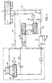
- the air conditioning system shown in Figure 1 includes a chiller 10, a heat exchanger 11, a cooling tower 20 and a filter 21. These elements are interconnected such that the heat exchanger 11 can be cooled either by the chiller 10 or by water from the cooling tower 20. In this latter case the water must first be filtered by filter 21.
- This system is described in detail in our co-pending British Patent Application No. 2,093,982A.
- the filter 21 contains a number of elongate filter elements through which the water normally flows from outside to in. Provision is made for backwashing the element either simultaneously or separately when the elements become blocked.
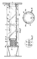
- FIG. 2 shows a filter element according to the invention for use in the filter 21.
- the filter element generally indicated at 30 comprises a spring 31, which is held coaxially with and between an inlet 32 and an outlet 33 by means of a cage 34.
- the normal flow through the filter is indicated by the solid arrows.
- the spring 31 has a generally square cross-section and is formed with lateral projections 35 along one edge. These projections define a minimum filter gap between adjacent segments of the spring.
- One end 36 of the spring is welded to an annulus 37 which is fixed in the outlet 33, whilst the other end 38 is secured to a cup-shaped member 39 which closes it.
- the cup-shaped member 39 forms an abutment for a compression spring 40 which serves to compress the filter spring 31, during normal operation, to maintain the minimum filter gap.
- the cage 34 comprises three axially extending rods 34a interconnected at both ends and contained by a spiral wire42. This construction of cage is particularly advantageous, because the spring decreases slightly in cross-section during extension and there is thus no frictional snagging between the spring 31 and the cage 34. This helps to ensure equal opening of the gaps 41.
- spiral wire 42 will help to swirl liquid along the length of the element 30 during normal flow causing the full length of the filter to be used.
- FIG. 5 An example is shown in Figures 5 and 6.
- the other end 38 of the spring 31 is connected to a slidable carriage 43.
- This carriage can be moved axially to the left (i.e. to extend the spring) by a lever mechanism generally indicated at 44.
- the lever mechanism comprises a pair of levers 45 connected in scissor formation and pivoted between their ends about a fixed pivot 46.
- One end 47 of each lever is located in a respective aperture 48 in the carriage 43, whilst the other end 49 is slidably mounted on a block 50 by means of a respective pin 51.
- the block 50 is axially slidable within the cage 34 and each pin is slidably mounted in the block by means of a respective lateral slot 52.
- the block 50 is maintained in its solid line position by means of the liquid pressure and/or suitable springs (not shown) acting on the block 50 and/orthe carriage 43.
- the block 50 is urged axially to the right causing the levers 45 to open, as indicated by the arrows, drawing the carriage 43 into its dotted line or lefthand position and hence extending the spring 31.
- the filter is connected to a reservoir 53 by a backwash drainpipe 54.
- the reservoir 53 is further connected to the filter 21, via a pump 55, by means of an inlet pipe 56.
- the reservoir 53 comprises a tank 57, which is sub-divided into internal compartments 58, 59 and 60.
- the compartments are interconnected by weirs 61 and 62 such that water initially flows into the compartment 58, then into 59 and finally into 60. This arrangement ensures that the majority of the contaminant settles in the compartment 58 and can be removed, for example through a draincock 63.
- a filter element 64 which may be, for example, the element shown in Figure 2, is disposed in the downstream-most compartment 60.
- the interior of the element 64 is connected to the pump 55 so that water can be drawn from the compartment 60, through the filter element 64, and pumped back into the system via the inlet pipe 56. Provision for backwashing the element 64 is schematically indicated at 65.
- the reservoir 53 can be utilised in a number of ways. Most simply it can be used merely for reinjecting backwash fluid resulting from normal backwash of the filter. However, more beneficially the control of the air conditioning system can be arranged so that the elements are backwashed intermittently and fluid from the compartment 60 can be reinjected in the periods between backwash. Indeed to guard against draining down of the cooling tower it is preferred that each backwash is limited to a certain quantity of liquid, e.g. 10 gallons, so that backwashing occurs almost continuously on an intermittent basis.
- the reservoir 53 may form a permanent attachment to the liquid system, but alternatively it may be utilised as a separate temperature unit for cleansing dirty systems, particularly on a pre-commissioning basis.
- the backwash pressure activated extension mechanisms may be replaced by externally operable piston, rams etc., which can be controlled in accordance with the operation of the fitter.
- the provision of convergent faces 66 on the spring 31 may also enhance opening of the gaps 41.
- the spring 31 may be located around a perforate cylinder rather than by the cage 34, but this is less satisfactory as frictional snagging will occur.
Landscapes
- Chemical & Material Sciences (AREA)
- Chemical Kinetics & Catalysis (AREA)
- Glass Compositions (AREA)
- Networks Using Active Elements (AREA)
- Piezo-Electric Or Mechanical Vibrators, Or Delay Or Filter Circuits (AREA)
- Filtration Of Liquid (AREA)
- Filtering Of Dispersed Particles In Gases (AREA)
Claims (6)
Priority Applications (1)
| Application Number | Priority Date | Filing Date | Title |
|---|---|---|---|
| AT83305121T ATE31632T1 (de) | 1982-09-11 | 1983-09-05 | Filterelement. |
Applications Claiming Priority (2)
| Application Number | Priority Date | Filing Date | Title |
|---|---|---|---|
| GB8225981 | 1982-09-11 | ||
| GB8225981 | 1982-09-11 |
Publications (3)
| Publication Number | Publication Date |
|---|---|
| EP0106485A2 EP0106485A2 (de) | 1984-04-25 |
| EP0106485A3 EP0106485A3 (en) | 1984-11-21 |
| EP0106485B1 true EP0106485B1 (de) | 1988-01-07 |
Family
ID=10532860
Family Applications (1)
| Application Number | Title | Priority Date | Filing Date |
|---|---|---|---|
| EP83305121A Expired EP0106485B1 (de) | 1982-09-11 | 1983-09-05 | Filterelement |
Country Status (5)
| Country | Link |
|---|---|
| EP (1) | EP0106485B1 (de) |
| AT (1) | ATE31632T1 (de) |
| AU (1) | AU1876983A (de) |
| DE (1) | DE3375080D1 (de) |
| ZA (1) | ZA836653B (de) |
Families Citing this family (3)
| Publication number | Priority date | Publication date | Assignee | Title |
|---|---|---|---|---|
| CN108826555A (zh) * | 2018-08-21 | 2018-11-16 | 广东惠恩建筑科技有限公司 | 空调水循环系统 |
| CN109019942B (zh) * | 2018-10-26 | 2023-08-25 | 珠海格力电器股份有限公司 | 净水机壳体及具有其的净水机 |
| CN112706333B (zh) * | 2020-12-01 | 2022-11-29 | 机械工业第九设计研究院股份有限公司 | 一种汽车内饰a柱护板生产用自动抓取设备 |
Family Cites Families (2)
| Publication number | Priority date | Publication date | Assignee | Title |
|---|---|---|---|---|
| DE2442345A1 (de) * | 1974-09-04 | 1976-03-18 | Bayer Ag | Rueckspuel-filter zur abwasser-reinigung |
| US4277261A (en) * | 1979-03-14 | 1981-07-07 | Edo Corporation | Reusable helical filter for high temperature gases |
-
1983
- 1983-09-05 AT AT83305121T patent/ATE31632T1/de not_active IP Right Cessation
- 1983-09-05 EP EP83305121A patent/EP0106485B1/de not_active Expired
- 1983-09-05 DE DE8383305121T patent/DE3375080D1/de not_active Expired
- 1983-09-06 AU AU18769/83A patent/AU1876983A/en not_active Abandoned
- 1983-09-07 ZA ZA836653A patent/ZA836653B/xx unknown
Also Published As
| Publication number | Publication date |
|---|---|
| ZA836653B (en) | 1984-04-25 |
| EP0106485A2 (de) | 1984-04-25 |
| EP0106485A3 (en) | 1984-11-21 |
| AU1876983A (en) | 1984-03-15 |
| ATE31632T1 (de) | 1988-01-15 |
| DE3375080D1 (en) | 1988-02-11 |
Similar Documents
| Publication | Publication Date | Title |
|---|---|---|
| CA1113020A (en) | Filter assembly with replaceable filter element | |
| US2988227A (en) | Pleated filter | |
| JP2009008071A (ja) | オイルフィルタ装置 | |
| DE1761106C3 (de) | Filter zur Reinigung von mit Feststoffen vermischten Flüssigkeiten | |
| US2748948A (en) | Filtering device | |
| EP0106485B1 (de) | Filterelement | |
| US4944887A (en) | Regenerative diatomaceous earth filter | |
| GB2126915A (en) | Filter element | |
| US3276588A (en) | Liquid filter | |
| US3282428A (en) | Multiple filter devices | |
| US3288289A (en) | Mobile filter with contaminant collecting means | |
| US5137555A (en) | Frontal drain for a marine mist extractor | |
| JPH08238404A (ja) | 弾性メンブレンプレスフィルタ及びろ過方法 | |
| US3113925A (en) | Fluid filters | |
| KR101889073B1 (ko) | 연속 자세식 스트레이너 | |
| JPS63294911A (ja) | 濾過機 | |
| EP0084520B1 (de) | Filtersystem | |
| JPS60212204A (ja) | 濾過要素 | |
| DE4101701C2 (de) | Filter für Kühlflüssigkeit | |
| US3269540A (en) | Multiple filter devices | |
| EP0275819B1 (de) | Labyrinthfilter für das Dielektrikum von Erodieranlagen | |
| US3425558A (en) | Backwash means for dual filter elements | |
| WO1999010073A1 (en) | High efficiency backflush system for a filter | |
| JP3492429B2 (ja) | フィルタエレメント | |
| AT376140B (de) | Verfahren und vorrichtung zur automatischen entfernung von festen verunreinigungen aus einer fluessigkeit |
Legal Events
| Date | Code | Title | Description |
|---|---|---|---|
| PUAI | Public reference made under article 153(3) epc to a published international application that has entered the european phase |
Free format text: ORIGINAL CODE: 0009012 |
|
| AK | Designated contracting states |
Designated state(s): AT BE CH DE FR GB IT LI LU NL SE |
|
| PUAL | Search report despatched |
Free format text: ORIGINAL CODE: 0009013 |
|
| AK | Designated contracting states |
Designated state(s): AT BE CH DE FR GB IT LI LU NL SE |
|
| 17P | Request for examination filed |
Effective date: 19850520 |
|
| RAP1 | Party data changed (applicant data changed or rights of an application transferred) |
Owner name: ENDLESS ENERGY GROUP LIMITED |
|
| GRAA | (expected) grant |
Free format text: ORIGINAL CODE: 0009210 |
|
| AK | Designated contracting states |
Kind code of ref document: B1 Designated state(s): AT BE CH DE FR GB IT LI LU NL SE |
|
| PG25 | Lapsed in a contracting state [announced via postgrant information from national office to epo] |
Ref country code: NL Effective date: 19880107 Ref country code: LI Effective date: 19880107 Ref country code: IT Free format text: LAPSE BECAUSE OF FAILURE TO SUBMIT A TRANSLATION OF THE DESCRIPTION OR TO PAY THE FEE WITHIN THE PRESCRIBED TIME-LIMIT;WARNING: LAPSES OF ITALIAN PATENTS WITH EFFECTIVE DATE BEFORE 2007 MAY HAVE OCCURRED AT ANY TIME BEFORE 2007. THE CORRECT EFFECTIVE DATE MAY BE DIFFERENT FROM THE ONE RECORDED. Effective date: 19880107 Ref country code: CH Effective date: 19880107 Ref country code: AT Effective date: 19880107 |
|
| REF | Corresponds to: |
Ref document number: 31632 Country of ref document: AT Date of ref document: 19880115 Kind code of ref document: T |
|
| PG25 | Lapsed in a contracting state [announced via postgrant information from national office to epo] |
Ref country code: SE Effective date: 19880131 |
|
| REF | Corresponds to: |
Ref document number: 3375080 Country of ref document: DE Date of ref document: 19880211 |
|
| ET | Fr: translation filed | ||
| REG | Reference to a national code |
Ref country code: CH Ref legal event code: PL |
|
| NLV1 | Nl: lapsed or annulled due to failure to fulfill the requirements of art. 29p and 29m of the patents act | ||
| PG25 | Lapsed in a contracting state [announced via postgrant information from national office to epo] |
Ref country code: LU Free format text: LAPSE BECAUSE OF NON-PAYMENT OF DUE FEES Effective date: 19880930 |
|
| PLBE | No opposition filed within time limit |
Free format text: ORIGINAL CODE: 0009261 |
|
| STAA | Information on the status of an ep patent application or granted ep patent |
Free format text: STATUS: NO OPPOSITION FILED WITHIN TIME LIMIT |
|
| 26N | No opposition filed | ||
| REG | Reference to a national code |
Ref country code: GB Ref legal event code: 732 |
|
| REG | Reference to a national code |
Ref country code: FR Ref legal event code: TP |
|
| PGFP | Annual fee paid to national office [announced via postgrant information from national office to epo] |
Ref country code: GB Payment date: 20000901 Year of fee payment: 18 |
|
| PGFP | Annual fee paid to national office [announced via postgrant information from national office to epo] |
Ref country code: FR Payment date: 20000914 Year of fee payment: 18 |
|
| PGFP | Annual fee paid to national office [announced via postgrant information from national office to epo] |
Ref country code: DE Payment date: 20001129 Year of fee payment: 18 |
|
| PGFP | Annual fee paid to national office [announced via postgrant information from national office to epo] |
Ref country code: BE Payment date: 20001130 Year of fee payment: 18 |
|
| PG25 | Lapsed in a contracting state [announced via postgrant information from national office to epo] |
Ref country code: GB Free format text: LAPSE BECAUSE OF NON-PAYMENT OF DUE FEES Effective date: 20010905 |
|
| PG25 | Lapsed in a contracting state [announced via postgrant information from national office to epo] |
Ref country code: BE Free format text: LAPSE BECAUSE OF NON-PAYMENT OF DUE FEES Effective date: 20010930 |
|
| BERE | Be: lapsed |
Owner name: CROSS MFG CY (1938) LTD Effective date: 20010930 |
|
| PG25 | Lapsed in a contracting state [announced via postgrant information from national office to epo] |
Ref country code: DE Free format text: LAPSE BECAUSE OF NON-PAYMENT OF DUE FEES Effective date: 20020501 |
|
| PG25 | Lapsed in a contracting state [announced via postgrant information from national office to epo] |
Ref country code: FR Free format text: LAPSE BECAUSE OF NON-PAYMENT OF DUE FEES Effective date: 20020531 |
|
| REG | Reference to a national code |
Ref country code: FR Ref legal event code: ST |