EP0106451A2 - Dispositif de fixation - Google Patents
Dispositif de fixation Download PDFInfo
- Publication number
- EP0106451A2 EP0106451A2 EP83304697A EP83304697A EP0106451A2 EP 0106451 A2 EP0106451 A2 EP 0106451A2 EP 83304697 A EP83304697 A EP 83304697A EP 83304697 A EP83304697 A EP 83304697A EP 0106451 A2 EP0106451 A2 EP 0106451A2
- Authority
- EP
- European Patent Office
- Prior art keywords
- base member
- aperture
- fastening device
- threaded member
- free
- Prior art date
- Legal status (The legal status is an assumption and is not a legal conclusion. Google has not performed a legal analysis and makes no representation as to the accuracy of the status listed.)
- Granted
Links
- 210000002105 tongue Anatomy 0.000 description 3
- 230000002708 enhancing effect Effects 0.000 description 2
- 239000000463 material Substances 0.000 description 2
- 230000015572 biosynthetic process Effects 0.000 description 1
- 230000037431 insertion Effects 0.000 description 1
- 238000003780 insertion Methods 0.000 description 1
- 239000002184 metal Substances 0.000 description 1
Images

Classifications
-
- F—MECHANICAL ENGINEERING; LIGHTING; HEATING; WEAPONS; BLASTING
- F16—ENGINEERING ELEMENTS AND UNITS; GENERAL MEASURES FOR PRODUCING AND MAINTAINING EFFECTIVE FUNCTIONING OF MACHINES OR INSTALLATIONS; THERMAL INSULATION IN GENERAL
- F16B—DEVICES FOR FASTENING OR SECURING CONSTRUCTIONAL ELEMENTS OR MACHINE PARTS TOGETHER, e.g. NAILS, BOLTS, CIRCLIPS, CLAMPS, CLIPS OR WEDGES; JOINTS OR JOINTING
- F16B37/00—Nuts or like thread-engaging members
- F16B37/04—Devices for fastening nuts to surfaces, e.g. sheets, plates
- F16B37/041—Releasable devices
Definitions
- This invention relates generally to a fastening device for securing an externally threaded member such as a screw that utilizes a combination of spaced-apart free ends of a pair of diammetrically opposed resilient fingers and helically deformed edge of an aperture through which the threaded member is inserted for engagement with the threads of the threaded member and more particularly to such device that includes a slot portion extending radially from the aperture as a means of separating higher and lower portions of the helical edge.
- This invention is an improvement of the fastening device disclosed in United States patent 3,308,708 assigned to the assignee of the present invention, the disclosure of which is incorporated herein by reference.
- Fastening devices for securing an externally threaded member such as a screw which utilize one or more resilient fingers or helically deformed edges surrounding an aperture through which the threaded member is inserted or combinations of both for engagement with the threads of the threaded member are well known in the art. Examples of fasteners utilizing free ends of resilent fingers or tongues for engagement with the threads of a threaded member are disclosed in United States Patents 2,239,797; 2,318,708; and 4,200,027, respectively. Examples of fastening devices which utilize a helically deformed edge of an aperture through which the threaded member is inserted are respectively disclosed in United States Patents 2,228,584; 2,901,938; and 3,362,278.
- fasteners which use a combination of resilient fingers or tongues and a helically deformed edge of an aperture surrounding an opening through which the threaded member is inserted are respectively disclosed in United States Patents 2,434,844; 2,494,882; and 3,308,708.
- the present invention concerns fasteners of the latter type particularly of the type disclosed in United States Patent 3,308,708 involving the use of resilient fingers in combination with a helically warped edge of an aperture through which the threaded member is inserted for engagement of the free ends of the resilient fingers and the helically formed edge with the threads of the threaded member.
- fasteners of the combination type described above may be used to advantage in providing a means of securing a threaded member
- fasteners have a tendency to cock (i.e. tilt) the threaded member and cause undesirable cross-threading to occur.
- the problem has been found to be particularly prevalent when the leading end of the threaded member is flat rather than pointed (such threaded mmbers in the form of screws are typically referred to as "blunt nosed" screws).
- an object of this invention to provide an improved fastening device for securing an externally threaded member of the type utilizing a combination of resilient fingers and helically formed edges surrounding an aperture through which the threaded member is inserted that minimizes the tendency for cocking and cross-threading the threaded member.
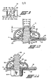
- FIGURE 1 shows an embodiment of the fastening device of the invention in the form of device 70.
- Device 70 has a base member 12 having an aperture 40 therethrough as illustrated in FIGURE 3.
- Aperture 40 is dimensionally adapted to receive the threaded member to which device 70 is to be secured.
- the marginal edges of aperture 40 are deformed into a generally frusto-conical projection .14 that projects upwardly from base member 12.
- Projection 14 has a helical edge extending between a higher portion 16 and a lower portion 16a thereof that are separated by a slot or slot portion 38 as shown in FIGURES 2, 3 and 4.
- edge portions 16 and 16a are preferably substantially the same as the pitch of the external threads of the threaded member to be inserted through aperture 40 and provides one of the thread engaging means for securing the threaded member to device 70.
- Projection 14 is also referred to a "helical thread impression" and is generally well known in the prior art.
- a pair of resilient finger portions 30 and 32 made integral with base member 12 extend upwardly and angularly inwardly from base member 12 on opposite sides of aperture 40 as shown in FIGURE 1.
- Finger portions 30 and 32 extend radially inwardly towards one another in overhanging relationship to frusto-conical projection 14.
- Finger portions 30 and 32 have free-ends 34 and 36 respectively that face towards each other and are spaced-apart from one another along axis "y-y" as shown in FIGURE 2.
- Aperture 40 is substantially axially aligned with a vertical plane drawn through axis y-y.
- Free-ends 34 and 36 of finger portions 30 and 32 are respectively axially off-set relative to one another such that free-end 36 of finger portions 32 is higher relative base member 12 than free-end 34 of finger portion 30 by distance "X".
- distance "X” is preferably substantially the same as the thread pitch of the threaded member to be secured to device 70.
- the inner diameter of the helically formed edge between lower portion 16a and upper portion 16a and the space between free-ends 34 and 36 along axis "y-y" are dimensionally adapted to engage with the threaded member inserted upwardly through aperture 40 and the space between free-ends 34 and 36 as described in more detail with respect to FIGURES 10 and 11.
- Resilient arm 22 of base member 12 extends downwardly from base member 12 at intersection 20 and preferably extends angularly upwardly towards base member 12 to an end 24 thereof that is spaced-apart from body member 12 for a distance sufficient for body member 12 and arm ' 22 to coact with each other to provide an open-ended clip.
- the length of arm 22 at intersection 20 may be varied to provide the amount of flexibility desired between arm 22 and base member 12 and the distance between arm 22 and base member 12 may be varied to accommodate the particular thickness of the article, such as a plate, to which device 70 is to be secured.
- arm 22 and base member 12 may be tapered in any manner as a means of enhancing the flexibility therebetween to the degree desired.
- End 18 of body member 12 is preferably flared upwardly away from arm 22 to faciliate inserting an article such as a plate or the like that is dimensionally capable of being inserted through the opening between base member 12 and arm 22.
- Arm 22 has an opening 28 therethrough that is substantially coaxially aligned with aperture 40 and dimensionally adapted to receive the threaded member to which device 70 is to be secured and enable the threaded member to be inserted through aperture 40 and thence turned such that it moves upwardly and the threads thereof engage with the helical edge between high portion 16 and low portion 16a and thence with free-ends 34 and 36 respectively of finger portions 30 and 32.
- Arm 22 may have a warped edge 26 which engages with the marginal portions of-an aperture, not referenced, through the article which is to be secured to device 70.
- device 70 is able to bd clipped onto an article such as a panel or the like having an opening therethrough that aligns substantially coaxially with opening 28 which in turn aligns substantially coaxially with aperture 40 which in turn aligns with a verticle plane drawn along axis "y-y" such that the threaded member can be inserted through opening 28 and the opening in the article and thence through aperture 40 for engagement with the helical edge extending between high portion 16 and low portion 16a.
- FIGURE 2 is a top view of device 70 of FIGURE 1 showing slot portion 38 extending radially outwardly through projection 14 from aperture 40 so as to separate high portion 16 and low portion 16a of the helically formed edge of projection 14 as further shown in FIGURE 3.
- Fasteners utilizing a combination of helically formed edges and the free-ends of fingers or tongues have heretofore had the problem that the threaded member would often cock as it was turned for securement with the fastener and often would suffer cross-threading as a result of the cocked position and that such was particuarly characteristic when the threaded member had a flattened or blunt end rather than pointed.
- such fasteners characteristically disposed the slot portion through the helical projection in a direction substantially parallel to the axis defined between the free ends of the finger portions. It has been surprisingly discovered that the tendency for cocking and cross-threading of the threaded member is markedly reduced when slot 38 extends radially outwardly from aperture 40 in a direction substantially transverse to axis "y-y" towards (and beneath) the finger portion having the higher free-end relative base member 12.
- FIGURE 2 also illustrates that the free-end 34 of finger portion 30 and free-end 36 of finger portion 32 preferably have concavely shaped edges 41 and 41a respectively that are preferably adapted to conform with the radius of curvature of the threaded member to which device 70 is to be secured. Varying the radius of curvature of edges 41 and 41a may be used to advantage in controlling the amount of torque exerted on the threaded member to secure device 70 to an article.
- Slot 38 extends through projection 14 towards finger portion 32 in a direction substantially transverse to axis "y-y" as previously described with respect to FIGURE 1.
- Finger portions 30 and 32 preferably have tapered edges 35 tapered such that the width of free-ends 34 and 36 along axis "y-y" is shorter than the width of finger portions 30 and 32 at the respective line of intersection between base member 12 and finger portions 30 and 32. Tapering of finger portions 30 and 32 provides a means of controlling the flexibility thereof to the degree desired which in turn provides a means of controlling the torque required to secure device 70 to an article. Generally, finger portions 30 and 32 may be tapered in any manner to enhance the flexibility thereof with respect to base member 12 to the degree desired.
- Arm 22 is preferably tapered outwardly towards intersection 20 and base member 12 is preferably tapered outwardly from intersection 20 to the line of intersection between base member 12 and finger portion 30 to provide a means of increasing the flexibility between arm 22 and base member 12 to the degree desired so as to enhance the ease of application of device 70 to the article to which it is to be secured and to control the torque required to secure device 70 to the article as well as prevent damage to the article.
- arm 22 and base member 12 may be tapered in such a manner as to enhance the flexibility therebetween to the degree desired.
- FIGURE 3 is a view taken along line 3-3 of FIGURE 1 which better illustrates aperture 40, lower portion 16, and higher portion 16a of the helical edge of projection 14 extending from base member 12 and slot 38 as previously described.
- Slot 38 extends radially outwardly through projection 14 as previously described for a distance sufficient to enable the formation of higher portion 16 and lower portion 16a of the helically deformed edge of projection 14 in the manner desired.
- FIGURE 4 shows a bottom view of device 70 of FIGURE 1 showing opening 28 through arm 22, aperture 40 through base member 12, and slot 38 separating high portion 16 and lower portion 16a of the helically formed edge of projection 14.
- FIGURE 5 shows an embodiment of the fastening device of the invention in the form of device 72.
- Device 72 has a substantially flat base member 12 having an opening 42 for receiving the threaded member.
- a generally frusto-conical projection 14 projects upwardly from base member 12 having a helically formed upper edge ending in lower portion 16 and higher portion 16a supported by slot portion 38 as previously described.
- Projection 14 is formed by deforming marginal edge portions of an aperture, not shown, through projection 14 that is substantially coaxially aligned with opening 42.
- Finger portions 30 and 32 extend angularly upwardly and inwardly over projection 14 with the free-end of finger portion 32 displaced axially higher relative base member 12 than the free-end of finger portion 30 as previously described.
- a slot portion separating higher portion 16 and lower portion 16a of projection 14 extends beneath and towards finger portion 32 in a direction substantially transverse to an axis defined between the free-ends of finger portions 30 and 32 as previously described.
- Device 72 is useful where it is desired to secure the device of the invention to the top of an article by suitable means.
- FIGURE 6A shows an embodiment of the fastening device of the invention in the form of device 74.
- Device 74 is substantially the same as device 70 described with respect to FIGURES 1, 2 and 3 excepting that a warped portion 44 extends angularly from arm 22 in a direction towards intersection 20 between base member 12 and arm 22.
- An opening 48 extends through portion 44 and is substantially coaxially aligned and dimensionally adapted so that the threaded member can be inserted through opening 48 and thence through the aperture, not referenced, surrounded by projection 14.
- Portion 44 may additionally include a warped edge 46 to provide engagement with marginal portions of an aperture through the article to which device 72 is to be secured. Warped portion 44 further enhances the engagement between device 74 and the article to which it is to be secured.
- FIGURE 6B shows a bottom view of device 74 of FIGURE 6A.
- Warped portion 44 is preferably tapered as shown in FIGURE 6B to improve the flexibility thereof which in turn enhances the ease with which device 74 can be applied to the article to which it is to be secured as well as providing a means of preventing damage to the article both before and after device 70 is secured to the article.
- warped portion 44 may be tapered in any manner to enhance the flexibility between portion 44 and arm 22 to the degree desired.
- Arm 22 preferably has notches 23 as shown in FIGURE 6B which enables the tapering of arm 22 between notches 23 and intersection 20 and of base member 12 between intersection 20 and the intersection between finger portion 30 and base member 12 to enhance the flexibility between arm 22 and base member 12 to the degree desired as a means of enhancing the ease with which device 74 may be applied to an article as well as providing a means of preventing damage to the article both before and after device 74 is secured to the article.
- FIGURES 7 and 8 show an embodiment of the fastening device of the invention in the form of device 76.
- Device 76 is substantially the same as device 72 of FIGURE 5 excepting a pair of flanges 48 extend from opposite sides of base member 12.
- Flanges 48 are dimensionally adapted to be disposed within a generally polygonal shaped opening in an article through which the threaded member is to be inserted. The upper sides of flanges 48 are drawn against the inner surface of the opening when the threaded member is tightly secured to device 76.
- flanges 48 are preferably bowed downwardly and then outwardly from base member 12 to enhance their effectiveness in attaching to the article.
- Flange 48 may further include ribs 50 on the upper surface thereof as shown in FIGURE 8 to even further enhance the ability of device 76 to be tightly secured to the article and may further include projections 52 cut out at the juncture between base member 12 and flanges 48 for engagement with marginal edges of the opening in the article to prevent lateral shifting movement of device 70 when in assembled position with the article.
- the device of the invention may include two or more of such flanges when such are desired.
- FIGURE 9 shows a fastening device of the invention in the form of device 78.
- Device 78 is substantially the same as devices 70, 72, 74 and 76' previously described excepting that slot portion 38 extends along base member 12 and thence along finger portion 32 to the free-end 36 thereof spaced apart from free-end 34 of finger portion 30 to divide finger portion 32 into portions 32 and 32a and free-end 36 into free-end portions 36 and 36a as shown in FIGURE 9.
- free-end 34 and the edges of end portions 36 and 36a of free-end 36 have a concave shape 54 as shown in FIGURE 9 positioned substantially coaxially with aperture 40 that is adapted to conform to the radius of curvature of the threaded member to be secured to device 78.
- the radius of curvature of concave shape 54 may be varied to control the amount of torque desired to secure device 78 to an article.
- Device 78 illustrates that, although slot portion 38 preferably need only extend through projection 14 and base member 12 for a distance sufficient to enable the helical edge of projection 14 to be formed in the manner desired, it may extend further along base member 12 and, if for some advantage, further along arm 32 when desired.
- FIGURES 10 and 11 respectively show an externally threaded member "S", such as a screw, inserted into and tightly securing an article such as plate “P” to device 70 of FIGURES 1, 2, 3 and 4 excepting that arm 22 has an outwardly flared end 39 as shown in FIGURES 10 and 11 to facilitate the insertion of plate "P" into the open ended clip formed between base member 12 and arm 22.
- S externally threaded member
- arm 22 has an outwardly flared end 39 as shown in FIGURES 10 and 11 to facilitate the insertion of plate "P" into the open ended clip formed between base member 12 and arm 22.
- diameter "a” of the helically formed edge of the frusto-conical projection and the width "c” of the space between the free-ends of the finger portions of the device of the invention are dimensionally adapted to enable the device to be securely fastened to the threaded member.
- the diameter "a” of the helical edge of projection 14 is such that, when threaded member "s” is intially inserted through the aperture surrounded by projection 14, the opposite sides of the helical edge impinge against lower surfaces 62 and 62a of external threads 56 as shown in FIGURE 10.
- slot portion 38 extends radially outwardly from the aperture surrounded by projection 14 towards (and beneath) the finger portion having a higher free-end relative the base member of the device in a direction substantially transverse to the axis defined between the free-ends of the finger portions.
- the axial distance between corresponding aligned points on the helical edge of projection 14 and the free-ends of finger portions 30 and 32 is substantially greater after tightening member "S" than when member "S" was intially positioned in the device of the invention before tightening.
- fastening devices of the invention may be made from any suitable metallic or polymeric material having suitable resiliency, strength and other properties desired for a particular application
- sheet metal has been found to be of advantage in many applications for making the fastening device of the invention.
- variations in the thickness and type of material used as well as tapering of various portions of the device may be employed to provide the degree of flexibility desired for a particular application which in turn provides a means for preventing damage to the article to which the device is secured as well as controlling the torque desired to be applied to the threaded member to secure the device to the article in addition to enabling the device to collapse upon the application of higher torque than desired so that the device collapses without damage to the article.
Landscapes
- Engineering & Computer Science (AREA)
- General Engineering & Computer Science (AREA)
- Mechanical Engineering (AREA)
- Dowels (AREA)
- Slide Fasteners, Snap Fasteners, And Hook Fasteners (AREA)
Applications Claiming Priority (2)
| Application Number | Priority Date | Filing Date | Title |
|---|---|---|---|
| US06/430,449 US4508477A (en) | 1982-09-30 | 1982-09-30 | Fastening device |
| US430449 | 1982-09-30 |
Publications (3)
| Publication Number | Publication Date |
|---|---|
| EP0106451A2 true EP0106451A2 (fr) | 1984-04-25 |
| EP0106451A3 EP0106451A3 (en) | 1985-03-27 |
| EP0106451B1 EP0106451B1 (fr) | 1987-07-29 |
Family
ID=23707605
Family Applications (1)
| Application Number | Title | Priority Date | Filing Date |
|---|---|---|---|
| EP83304697A Expired EP0106451B1 (fr) | 1982-09-30 | 1983-08-15 | Dispositif de fixation |
Country Status (5)
| Country | Link |
|---|---|
| US (1) | US4508477A (fr) |
| EP (1) | EP0106451B1 (fr) |
| JP (1) | JPS5983822A (fr) |
| CA (1) | CA1220371A (fr) |
| DE (1) | DE3372808D1 (fr) |
Cited By (6)
| Publication number | Priority date | Publication date | Assignee | Title |
|---|---|---|---|---|
| FR2583470A1 (fr) * | 1985-06-12 | 1986-12-19 | Rapid Sa | Ecrou |
| EP0220526A1 (fr) * | 1985-10-12 | 1987-05-06 | A. Raymond KG | Ecrou en tôle à autoblocage formant pince |
| GB2241760A (en) * | 1990-03-06 | 1991-09-11 | Psm Int Plc | Securing of sheet metal nuts to panels |
| FR2697060A1 (fr) * | 1992-10-15 | 1994-04-22 | Rapid Sa | Ecrou en forme de pince en particulier pour connexion électrique. |
| WO1999022152A1 (fr) * | 1997-10-25 | 1999-05-06 | A. Raymond & Cie | Element de fixation semblable a un ecrou |
| EP3372916A1 (fr) * | 2017-03-10 | 2018-09-12 | Trox GmbH | Système de fixation amovible d'un composant d'une installation de climatisation et d'aéraulique |
Families Citing this family (21)
| Publication number | Priority date | Publication date | Assignee | Title |
|---|---|---|---|---|
| US4798507A (en) * | 1985-07-18 | 1989-01-17 | California Industrial Products, Inc. | Sheet metal U-nut |
| US4647263A (en) * | 1985-11-20 | 1987-03-03 | Simmons Fastener Corporation | Nut plate fastener |
| US4784553A (en) * | 1986-10-16 | 1988-11-15 | Casco Products Corporation | Vibration resistant fastener construction |
| US4729706A (en) * | 1987-04-01 | 1988-03-08 | Buell Industries, Inc. | Fastener clip |
| US4897005A (en) * | 1987-04-01 | 1990-01-30 | Buell Industries, Inc. | Gutted U-nut |
| DE3910423A1 (de) * | 1989-03-31 | 1990-10-04 | Raymond A Fa | Klammerartige blechmutter fuer automatische montage |
| JP2552984Y2 (ja) * | 1992-08-24 | 1997-11-05 | 勝寿 徳吉 | ボルト用締付クリップ |
| US5256018A (en) * | 1992-11-02 | 1993-10-26 | Eaton Corporation | Clip-on fastener |
| US5603524A (en) * | 1995-12-01 | 1997-02-18 | General Motors Corporation | Releasable fastener for air bag deployment cover |
| EP0778420A1 (fr) | 1995-12-04 | 1997-06-11 | Eaton Corporation | Dispositif de fixation à pince |
| US20050100424A1 (en) * | 1996-04-10 | 2005-05-12 | Distasio Robert J. | Locking nut, bolt and clip systems and assemblies |
| US5951224A (en) * | 1996-04-10 | 1999-09-14 | Permanent Technologies, Inc. | Locking nut and bolt system |
| US6010289A (en) * | 1996-04-10 | 2000-01-04 | Permanent Technologies, Inc. | Locking nut, bolt and clip systems and assemblies |
| US5707191A (en) * | 1996-12-13 | 1998-01-13 | Illinois Tool Works Inc. | Stress plate with angled hole |
| US5908278A (en) * | 1997-08-07 | 1999-06-01 | Illinois Tool Works Inc. | Stress plate with depending sleeve |
| DE29916793U1 (de) * | 1999-09-15 | 2000-01-05 | Itw Automotive Prod Gmbh & Co | Befestigungssystem |
| FR2841613B1 (fr) * | 2002-06-28 | 2004-12-24 | Itw De France | Dispositif comportant un cavalier pour la fixation d'une piece sur un panneau |
| US7189044B2 (en) | 2004-10-29 | 2007-03-13 | Permanent Technologies, Llc | Locking nut and bolt system with enhanced locking |
| JP2006308020A (ja) * | 2005-04-28 | 2006-11-09 | Piolax Inc | プッシュナット |
| FR2899658B1 (fr) * | 2006-04-10 | 2010-08-27 | Raymond A & Cie | Dispositif de serrage |
| WO2012166552A1 (fr) | 2011-06-02 | 2012-12-06 | A. Raymond Et Cie | Dispositifs de fixation fabriqués par impression en trois dimensions |
Citations (5)
| Publication number | Priority date | Publication date | Assignee | Title |
|---|---|---|---|---|
| US2255469A (en) * | 1940-08-01 | 1941-09-09 | Detroit Harvester Co | Fastener |
| US2400545A (en) * | 1944-09-01 | 1946-05-21 | Detroit Harvester Co | Sheet metal fastener |
| US2494882A (en) * | 1945-09-19 | 1950-01-17 | Prestole Corp | Sheet metal nut |
| US3308708A (en) * | 1964-08-14 | 1967-03-14 | Tinnerman Products Inc | Fastening device |
| US3523299A (en) * | 1965-09-20 | 1970-08-04 | George A Tinnerman | Thread engaging sheet metal fastener |
Family Cites Families (13)
| Publication number | Priority date | Publication date | Assignee | Title |
|---|---|---|---|---|
| USRE22049E (en) * | 1936-10-01 | 1942-03-10 | Spring fastener | |
| US2228584A (en) * | 1936-10-26 | 1941-01-14 | Detroit Harvester Co | Fastener clip |
| GB553463A (en) * | 1942-05-14 | 1943-05-21 | Bernard Arthur Parr | Improvements relating to sheet metal nuts |
| US2378258A (en) * | 1944-01-06 | 1945-06-12 | Tinnerman Products Inc | Fastening device |
| US2434844A (en) * | 1945-11-08 | 1948-01-20 | Tinnerman Products Inc | Fastening device |
| US2581481A (en) * | 1948-01-28 | 1952-01-08 | Tinnerman Products Inc | Fastening device |
| DE878126C (de) * | 1948-01-28 | 1953-06-01 | Tinnerman Products Inc | Blechklammer zur behelfsmaessigen Anbringung von Befestigungs-elementen |
| US2901938A (en) * | 1957-01-31 | 1959-09-01 | United Carr Fastener Corp | Self threading fastening bearing a helix the leading end of which is rounded to initiate thread rolling |
| US3362278A (en) * | 1966-05-06 | 1968-01-09 | Bishop & Babcock Corp | Nut impressions |
| US3426818A (en) * | 1967-05-08 | 1969-02-11 | California Ind Prod Inc | Yielding nut retainer |
| US3669170A (en) * | 1970-06-22 | 1972-06-13 | Westinghouse Electric Corp | U-shaped clip nut |
| US4200027A (en) * | 1977-08-22 | 1980-04-29 | Eaton Corporation | Fastening device |
| FR2489903B1 (fr) * | 1980-09-11 | 1987-07-31 | Sonofam | Ecrou a pince |
-
1982
- 1982-09-30 US US06/430,449 patent/US4508477A/en not_active Expired - Lifetime
-
1983
- 1983-08-11 CA CA000434366A patent/CA1220371A/fr not_active Expired
- 1983-08-15 DE DE8383304697T patent/DE3372808D1/de not_active Expired
- 1983-08-15 EP EP83304697A patent/EP0106451B1/fr not_active Expired
- 1983-09-29 JP JP58179480A patent/JPS5983822A/ja active Pending
Patent Citations (5)
| Publication number | Priority date | Publication date | Assignee | Title |
|---|---|---|---|---|
| US2255469A (en) * | 1940-08-01 | 1941-09-09 | Detroit Harvester Co | Fastener |
| US2400545A (en) * | 1944-09-01 | 1946-05-21 | Detroit Harvester Co | Sheet metal fastener |
| US2494882A (en) * | 1945-09-19 | 1950-01-17 | Prestole Corp | Sheet metal nut |
| US3308708A (en) * | 1964-08-14 | 1967-03-14 | Tinnerman Products Inc | Fastening device |
| US3523299A (en) * | 1965-09-20 | 1970-08-04 | George A Tinnerman | Thread engaging sheet metal fastener |
Cited By (6)
| Publication number | Priority date | Publication date | Assignee | Title |
|---|---|---|---|---|
| FR2583470A1 (fr) * | 1985-06-12 | 1986-12-19 | Rapid Sa | Ecrou |
| EP0220526A1 (fr) * | 1985-10-12 | 1987-05-06 | A. Raymond KG | Ecrou en tôle à autoblocage formant pince |
| GB2241760A (en) * | 1990-03-06 | 1991-09-11 | Psm Int Plc | Securing of sheet metal nuts to panels |
| FR2697060A1 (fr) * | 1992-10-15 | 1994-04-22 | Rapid Sa | Ecrou en forme de pince en particulier pour connexion électrique. |
| WO1999022152A1 (fr) * | 1997-10-25 | 1999-05-06 | A. Raymond & Cie | Element de fixation semblable a un ecrou |
| EP3372916A1 (fr) * | 2017-03-10 | 2018-09-12 | Trox GmbH | Système de fixation amovible d'un composant d'une installation de climatisation et d'aéraulique |
Also Published As
| Publication number | Publication date |
|---|---|
| DE3372808D1 (en) | 1987-09-03 |
| JPS5983822A (ja) | 1984-05-15 |
| US4508477A (en) | 1985-04-02 |
| EP0106451A3 (en) | 1985-03-27 |
| CA1220371A (fr) | 1987-04-14 |
| EP0106451B1 (fr) | 1987-07-29 |
Similar Documents
| Publication | Publication Date | Title |
|---|---|---|
| US4508477A (en) | Fastening device | |
| US2771113A (en) | Sheet metal lock nut with spring locking arm | |
| US4606688A (en) | Removable fastening assembly | |
| US6976292B2 (en) | Resilient clip fastener | |
| US3929054A (en) | Fastening element adapted for tightening to predetermined torque | |
| US4595325A (en) | Self-locking prevailing torque fastener | |
| US5707192A (en) | Panel--fastener connector clip | |
| EP0908638B1 (fr) | Dispositif de fixation avec écrou encagé | |
| US1881836A (en) | Clinch-on nut | |
| US20020028121A1 (en) | Fastening system | |
| US2168721A (en) | Bolt fastening device and the like | |
| EP0588467A1 (fr) | Ecrou destiné à être fixé dans une ouverture d'une plaque | |
| US3645311A (en) | Constant torque threaded fastener formation | |
| US2633886A (en) | Nut anchoring device | |
| US4705441A (en) | Self locking sheet metal screw | |
| US2883228A (en) | Closure fastener | |
| USRE22049E (en) | Spring fastener | |
| US3308708A (en) | Fastening device | |
| US4440535A (en) | Sheet metal fastener | |
| US5256018A (en) | Clip-on fastener | |
| US2516274A (en) | Fastening device | |
| US5593263A (en) | Snap-in fastener | |
| EP0919735B1 (fr) | Dispositif de fixation pour des panneaux minces | |
| US3614144A (en) | Expansion clip and method of installing recessed fixtures with such clips | |
| US4143696A (en) | Self-locking, self-retaining fastener |
Legal Events
| Date | Code | Title | Description |
|---|---|---|---|
| PUAI | Public reference made under article 153(3) epc to a published international application that has entered the european phase |
Free format text: ORIGINAL CODE: 0009012 |
|
| AK | Designated contracting states |
Designated state(s): DE FR GB |
|
| PUAL | Search report despatched |
Free format text: ORIGINAL CODE: 0009013 |
|
| AK | Designated contracting states |
Designated state(s): DE FR GB |
|
| 17P | Request for examination filed |
Effective date: 19850522 |
|
| 17Q | First examination report despatched |
Effective date: 19860204 |
|
| GRAA | (expected) grant |
Free format text: ORIGINAL CODE: 0009210 |
|
| AK | Designated contracting states |
Kind code of ref document: B1 Designated state(s): DE FR GB |
|
| REF | Corresponds to: |
Ref document number: 3372808 Country of ref document: DE Date of ref document: 19870903 |
|
| ET | Fr: translation filed | ||
| PLBE | No opposition filed within time limit |
Free format text: ORIGINAL CODE: 0009261 |
|
| STAA | Information on the status of an ep patent application or granted ep patent |
Free format text: STATUS: NO OPPOSITION FILED WITHIN TIME LIMIT |
|
| 26N | No opposition filed | ||
| PGFP | Annual fee paid to national office [announced via postgrant information from national office to epo] |
Ref country code: GB Payment date: 19920710 Year of fee payment: 10 |
|
| PGFP | Annual fee paid to national office [announced via postgrant information from national office to epo] |
Ref country code: DE Payment date: 19920828 Year of fee payment: 10 |
|
| PG25 | Lapsed in a contracting state [announced via postgrant information from national office to epo] |
Ref country code: GB Effective date: 19930815 |
|
| GBPC | Gb: european patent ceased through non-payment of renewal fee |
Effective date: 19930815 |
|
| PG25 | Lapsed in a contracting state [announced via postgrant information from national office to epo] |
Ref country code: DE Effective date: 19940503 |
|
| PGFP | Annual fee paid to national office [announced via postgrant information from national office to epo] |
Ref country code: FR Payment date: 19960816 Year of fee payment: 14 |
|
| PG25 | Lapsed in a contracting state [announced via postgrant information from national office to epo] |
Ref country code: FR Free format text: LAPSE BECAUSE OF NON-PAYMENT OF DUE FEES Effective date: 19980430 |
|
| REG | Reference to a national code |
Ref country code: FR Ref legal event code: ST |