EP0106045B1 - Earth leakage circuit breaker - Google Patents
Earth leakage circuit breaker Download PDFInfo
- Publication number
- EP0106045B1 EP0106045B1 EP83107658A EP83107658A EP0106045B1 EP 0106045 B1 EP0106045 B1 EP 0106045B1 EP 83107658 A EP83107658 A EP 83107658A EP 83107658 A EP83107658 A EP 83107658A EP 0106045 B1 EP0106045 B1 EP 0106045B1
- Authority
- EP
- European Patent Office
- Prior art keywords
- circuit
- breaker
- breaking device
- voltage
- earth leakage
- Prior art date
- Legal status (The legal status is an assumption and is not a legal conclusion. Google has not performed a legal analysis and makes no representation as to the accuracy of the status listed.)
- Expired
Links
Images
Classifications
-
- H—ELECTRICITY
- H02—GENERATION; CONVERSION OR DISTRIBUTION OF ELECTRIC POWER
- H02H—EMERGENCY PROTECTIVE CIRCUIT ARRANGEMENTS
- H02H3/00—Emergency protective circuit arrangements for automatic disconnection directly responsive to an undesired change from normal electric working condition with or without subsequent reconnection ; integrated protection
- H02H3/26—Emergency protective circuit arrangements for automatic disconnection directly responsive to an undesired change from normal electric working condition with or without subsequent reconnection ; integrated protection responsive to difference between voltages or between currents; responsive to phase angle between voltages or between currents
- H02H3/32—Emergency protective circuit arrangements for automatic disconnection directly responsive to an undesired change from normal electric working condition with or without subsequent reconnection ; integrated protection responsive to difference between voltages or between currents; responsive to phase angle between voltages or between currents involving comparison of the voltage or current values at corresponding points in different conductors of a single system, e.g. of currents in go and return conductors
- H02H3/33—Emergency protective circuit arrangements for automatic disconnection directly responsive to an undesired change from normal electric working condition with or without subsequent reconnection ; integrated protection responsive to difference between voltages or between currents; responsive to phase angle between voltages or between currents involving comparison of the voltage or current values at corresponding points in different conductors of a single system, e.g. of currents in go and return conductors using summation current transformers
- H02H3/332—Emergency protective circuit arrangements for automatic disconnection directly responsive to an undesired change from normal electric working condition with or without subsequent reconnection ; integrated protection responsive to difference between voltages or between currents; responsive to phase angle between voltages or between currents involving comparison of the voltage or current values at corresponding points in different conductors of a single system, e.g. of currents in go and return conductors using summation current transformers with means responsive to dc component in the fault current
-
- H—ELECTRICITY
- H01—ELECTRIC ELEMENTS
- H01H—ELECTRIC SWITCHES; RELAYS; SELECTORS; EMERGENCY PROTECTIVE DEVICES
- H01H83/00—Protective switches, e.g. circuit-breaking switches, or protective relays operated by abnormal electrical conditions otherwise than solely by excess current
- H01H83/14—Protective switches, e.g. circuit-breaking switches, or protective relays operated by abnormal electrical conditions otherwise than solely by excess current operated by unbalance of two or more currents or voltages, e.g. for differential protection
- H01H83/144—Protective switches, e.g. circuit-breaking switches, or protective relays operated by abnormal electrical conditions otherwise than solely by excess current operated by unbalance of two or more currents or voltages, e.g. for differential protection with differential transformer
-
- H—ELECTRICITY
- H02—GENERATION; CONVERSION OR DISTRIBUTION OF ELECTRIC POWER
- H02H—EMERGENCY PROTECTIVE CIRCUIT ARRANGEMENTS
- H02H1/00—Details of emergency protective circuit arrangements
- H02H1/04—Arrangements for preventing response to transient abnormal conditions, e.g. to lightning or to short duration over voltage or oscillations; Damping the influence of dc component by short circuits in ac networks
Definitions
- the invention relates to a residual current circuit breaker according to the preamble of claim 1.
- a known such residual current circuit breaker (US-A-4093977) has active electronic components between the summation current transformer and the tripping device, which are protected against overload by a voltage-dependent resistor connected in parallel with the summation current transformer.
- the invention is based, with simple means to upgrade a residual current circuit breaker of common design that works without active electronic components so that it is surge current-resistant.
- the problem described is solved by a residual current circuit breaker with the characterizing features of patent claim 1.
- the connecting lines to the tripping device are bridged by a voltage-dependent resistance of such a characteristic that, above a threshold, the resistance drops with increasing voltage.
- the threshold of the resistance is advantageously chosen so that it is just above the relevant response voltage. Voltage peaks caused by surge currents that are above the threshold are short-circuited in front of the tripping device.
- the solution described is therefore provided when no sensitive active electronic components such as transistors, thyristors or integrated circuits are used.
- the voltage-dependent resistor is designed to prevent false tripping of the residual current circuit breaker.
- the electronic circuit itself is protected against damage from overvoltages.
- the residual current circuit breaker can in particular have a summation current transformer, in the secondary circuit of which a release is arranged, based on the holding magnet principle.
- the solution described is also suitable for residual current circuit breakers that respond to DC components.
- Such a solution is known per se (DE-A-2036497).
- a capacitor is arranged in the secondary circuit in series with the trigger coil of the trigger, for example in the form of a holding magnet, which capacitor is at least approximately resonant with the frequency which a primary-side fault current causes on the secondary side.
- Such a residual current circuit breaker in conjunction with the voltage-dependent resistor described above is not only sensitive to residual currents with DC components, but it is also insensitive to surge currents, in accordance with recent requirements (for example, according to VDE 0664 Part 1 / 5.81).
- the capacitor for resonance tuning can be arranged in a manner known per se in the secondary circuit in parallel with the trigger between the voltage-dependent resistor and the trigger.
- Zener diodes in memory circuits of a known type (EP-A-0039280), whereby trigger signals are summed up in a residual current circuit breaker in a capacitor until the Zener diode transfers the stored energy to a release device.
- a zener diode is used to trigger a residual current circuit breaker with a memory circuit.
- the voltage-dependent resistance can be implemented in a manner known per se: it can be a varistor or can be formed by two Zener diodes which are opposite to one another in their forward direction.
- a residual current circuit breaker with memory is shown, which is provided with the precautions described above to be insensitive to surge currents, but sensitive to pulsating fault currents - that is, fault currents with DC components.
- the residual current circuit breaker according to FIG. 1 works with a release device 1, in the exemplary embodiment a release in the design as a holding magnet with the trip coil shown.
- the triggering device 1 is in engagement connection with a switch lock 2.
- the switch lock acts on switch contacts 4, which are arranged in lines 5 and 6 to be monitored.
- the connecting lines 7, 8 to the tripping device 1 are bridged by a voltage-dependent resistor 9.
- Resistor 9 has such a characteristic that, above a threshold, the resistance decreases with increasing voltage. It can be a varistor.
- the lines 5, 6 to be monitored can in particular form windings of a summation current transformer 10, in the secondary circuit of which a trigger with a trigger coil is arranged as a holding magnet. These then form the triggering device 1.
- a capacitor 11 is arranged in series with the trip coil, which capacitor is at least approximately resonant with the frequency in the secondary circuit, which causes a fault current on the primary side with DC components on the secondary side. This makes the residual current circuit breaker sensitive to residual currents with DC components.
- a capacitor 11 can also be arranged in the secondary circuit in parallel with the release, the release device 1, in order to make the residual current circuit breaker sensitive to residual currents with direct current components.
- the voltage-dependent resistor is formed by two Zener diodes 12 which are opposite in their forward direction.
- a rectifier bridge circuit 13 is arranged between the voltage-dependent resistor 9 and the release, the release device 1, in the bridge branch of which the release and, in parallel, a storage capacitor 14 with an upstream resistor 15 is arranged.
Abstract
Description
Die Erfindung bezieht sich auf einen Fehlerstromschutzschalter nach Gattungsbegriff von Patentanspruch 1. Ein bekannter derartiger Fehlerstromschutzschalter (US-A-4093977) weist aktive elektronische Bauelemente zwischen Summenstromwandler und Auslöseeinrichtung auf, die durch einen zum Summenstromwandler parallel geschalteten spannungsabhängigen Widerstand gegen Überlastung geschützt werden.The invention relates to a residual current circuit breaker according to the preamble of claim 1. A known such residual current circuit breaker (US-A-4093977) has active electronic components between the summation current transformer and the tripping device, which are protected against overload by a voltage-dependent resistor connected in parallel with the summation current transformer.
Gewitterüberspannungen in Niederspannungsanlagen und allgemein Schaltüberspannungen in elektrischen Anlagen können Fehlerstromschutzschalter auslösen, was zumindest lästig ist, in Einzelfällen auch zu Schaden führen kann. So beispielsweise bei Gefrier- und Kühlgeräten, in denen aufbewahrte Lebensmittel verderben können, wenn die Geräte unbemerkt abgeschaltet werden. Man fordert daher seit einiger Zeit, dass Fehlerstromschutzschalter stossstromfest sein sollen (beispielsweise gemäss VDE 033 eine Stossstromfestigkeit hinsichtlich 500 A und 8/20 gs). Dennoch sind zufriedenstellende Lösungen bisher nicht auf den Markt gelangt.Thunderstorm overvoltages in low-voltage systems and in general switching overvoltages in electrical systems can trigger residual current circuit breakers, which is at least annoying and can also lead to damage in individual cases. For example, in freezers and refrigerators where stored food can spoil if the devices are switched off without being noticed. For some time now, it has been required that residual current circuit breakers should be surge current proof (for example, according to VDE 033, a surge current resistance with regard to 500 A and 8/20 gs). However, satisfactory solutions have not yet reached the market.
Der Erfindung liegt die Aufgabe zugrunde, mit einfachen Mitteln einen Fehlerstromschutzschalter gängiger Bauart, der ohne aktive elektronische Bauelemente arbeitet, so zu ertüchtigen, dass er stossstromfest ist.The invention is based, with simple means to upgrade a residual current circuit breaker of common design that works without active electronic components so that it is surge current-resistant.
Die Lösung der geschilderten Aufgabe erfolgt durch einen Fehlerstromschutzschalter mit den kennzeichnenden Merkmalen des Patentanspruchs 1. Die Anschlussleitungen zur Auslöseeinrichtung sind also durch einen spannungsabhängigen Widerstand einer solchen Charakteristik überbrückt, dass, oberhalb einer Schwelle, mit steigender Spannung der Widerstand sinkt. Die Schwelle des Widerstandes wird günstigerweise so gewählt, dass sie gerade oberhalb der einschlägigen Ansprechspannung liegt. Spanungsspitzen durch Stossstrom, die oberhalb der Schwelle liegen, werden dabei vor der Auslöseeinrichtung kurzgeschlossen.The problem described is solved by a residual current circuit breaker with the characterizing features of patent claim 1. The connecting lines to the tripping device are bridged by a voltage-dependent resistance of such a characteristic that, above a threshold, the resistance drops with increasing voltage. The threshold of the resistance is advantageously chosen so that it is just above the relevant response voltage. Voltage peaks caused by surge currents that are above the threshold are short-circuited in front of the tripping device.
Die geschilderte Lösung wird also gerade dann vorgesehen, wenn keine empfindlichen aktiven elektronischen Bauelemente wie Transistoren, Thyristoren oder integrierte Schaltkreise verwendet werden. Der spannungsabhängige Widerstand ist darauf abgestimmt, Fehlauslösungen des Fehlerstromschutzschalters zu vermeiden. Beim eingangs geschilderten bekannten Fehlerstromschutzschalter (US-A-4093977) wird bei Einsatz von empfindlichen elektronischen Bauelementen (Transistoren Q1, Q2; Thyristor 60) die elektronische Schaltung selbst gegen Beschädigung durch Überspannungen geschützt. In einem derartigen Zusammenhang ist es bekannt (DE-A-2845993), durch einen Entlader (10 nach Fig. 3 oder 4) Schäden an der Elektronik selbst, insbesondere an Spannungs-Multiplikatoren (11 nach Fig. 1) zu vermeiden. Zum Schutz von umfangreichen elektronischen Schaltungen bei elektronischen Fehlerstromschutzschaltern ist es auch bekannt, bei (DE-A-2424205) empfindlichen elektronischen Bauelementen durch eine Zenerdiode parallel zum Summenstromwandler zusammen mit einer Reihenschaltung aus Kondensator und einem Widerstand auftretende Stromstösse zu absorbieren und von den zu schützenden Bauelementen abzuhalten. Erfindungsgemäss wird dagegen bei einem Fehlerstromschutzschalter ohne empfindliche elektronische Bauelemente, ohne aktive Bauelemente, ein spannungsabhängiger Widerstand der geschilderten Charakteristik zwischen die Anschlussleitungen zur Auslöseeinrichtung eingeschaltet, um Fehlauslösungen zu vermeiden.The solution described is therefore provided when no sensitive active electronic components such as transistors, thyristors or integrated circuits are used. The voltage-dependent resistor is designed to prevent false tripping of the residual current circuit breaker. In the known residual current circuit breaker (US-A-4093977) described at the outset, when using sensitive electronic components (transistors Q1, Q2; thyristor 60), the electronic circuit itself is protected against damage from overvoltages. In such a context, it is known (DE-A-2845993) to avoid damage to the electronics themselves, in particular to voltage multipliers (11 according to FIG. 1), by means of a discharger (10 according to FIG. 3 or 4). To protect extensive electronic circuits in electronic residual current circuit breakers, it is also known to (DE-A-2424205) sensitive electronic components by means of a zener diode parallel to the summation current transformer together with a series circuit comprising a capacitor and a resistor to absorb current surges that occur and from the components to be protected to hold. In contrast, according to the invention, in the case of a residual current circuit breaker without sensitive electronic components, without active components, a voltage-dependent resistor of the characteristic described is switched on between the connecting lines to the tripping device in order to avoid false tripping.
Der Fehlerstromschutzschalter kann insbesondere einen Summenstromwandler aufweisen, in dessen Sekundärkreis ein Auslöser, nach dem Haltemagnetprinzip, angeordnet ist. Überraschenderweise eignet sich die geschilderte Lösung auch bei Fehlerstromschutzschaltern, die auf Gleichstromkomponenten ansprechen. Eine solche Lösung ist für sich bekannt (DE-A-2036497). Danach ist im Sekundärkreis wirkungsmässig in Reihenschaltung zur Auslösespule des Auslösers, beispielsweise in der Ausbildung als Haltemagnet, ein Kondensator angeordnet, der auf die Frequenz zumindest in etwa resonant abgestimmt ist, die ein primärseitiger Fehlerstrom sekundärseitig hervorruft. Ein solcher Fehlerstromschutzschalter ist in Verbindung mit dem zuvor geschilderten spannungsabhängigen Widerstand nicht nur sensitiv für Fehlerströme mit Gleichstromkomponenten, sondern er ist auch unempfindlich gegen Stossströme, entsprechend neueren Forderungen (beispielsweise nach VDE 0664 Teil 1/5.81). Der Kondensator zur Resonanzabstimmung kann in an sich bekannter Weise im Sekundärkreis auch in Parallelschaltung zum Auslöser zwischen dem spannungsabhängigen Widerstand und dem Auslöser angeordnet sein.The residual current circuit breaker can in particular have a summation current transformer, in the secondary circuit of which a release is arranged, based on the holding magnet principle. Surprisingly, the solution described is also suitable for residual current circuit breakers that respond to DC components. Such a solution is known per se (DE-A-2036497). According to this, a capacitor is arranged in the secondary circuit in series with the trigger coil of the trigger, for example in the form of a holding magnet, which capacitor is at least approximately resonant with the frequency which a primary-side fault current causes on the secondary side. Such a residual current circuit breaker in conjunction with the voltage-dependent resistor described above is not only sensitive to residual currents with DC components, but it is also insensitive to surge currents, in accordance with recent requirements (for example, according to VDE 0664 Part 1 / 5.81). The capacitor for resonance tuning can be arranged in a manner known per se in the secondary circuit in parallel with the trigger between the voltage-dependent resistor and the trigger.
Dabei ist es bekannt, einen Fehlerstromschutzschalter zur Erfassung von Wechselfehlerströmen durch ein Zusatzteil nachträglich zu einem Fehlerstromschutzschalter umzurüsten, der auch bei Gleichfehlerströmen auslöst (DE-A-2429446).It is known to retrofit a residual current circuit breaker for detecting AC residual currents with an additional part to a residual current circuit breaker which also triggers in the case of DC residual currents (DE-A-2429446).
Eine andere Funktion erfüllen Zenerdioden in Speicherschaltungen bekannter Art (EP-A-0039280), wodurch bei einem Fehlerstromschutzschalter in einem Kondensator Auslösesignale aufsummiert werden, bis die Zenerdiode die gespeicherte Energie auf eine Auslöseeinrichtung gibt. Eine solche Zenerdiode dient also zum Auslösen eines Fehlerstromschutzschalters mit Speicherschaltung.Another function is performed by Zener diodes in memory circuits of a known type (EP-A-0039280), whereby trigger signals are summed up in a residual current circuit breaker in a capacitor until the Zener diode transfers the stored energy to a release device. Such a zener diode is used to trigger a residual current circuit breaker with a memory circuit.
Der spannungsabhängige Widerstand lässt sich in an sich bekannter Weise realisieren: Er kann ein Varistor sein oder durch zwei in ihrer Durchlassrichtung einander entgegengesetzt gerichtete Zenerdioden gebildet werden.The voltage-dependent resistance can be implemented in a manner known per se: it can be a varistor or can be formed by two Zener diodes which are opposite to one another in their forward direction.
Die Erfindung soll anhand von in derZeichnung grob schematisch wiedergegebenen Ausführungsbeispielen näher erläutert werden:
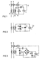
- In Fig. 1 ist ein Fehlerstromschutzschalter mit einem spannungsabhängigen Widerstand und mit einem Kondensator veranschaulicht, der unempfindlich gegen Stossströme, jedoch sensitiv für Fehlerströme mit Gleichstromkomponenten ist. In Fig. 2 ist ein Fehlerstromschutzschalter mit einem Sekundärkreis eines Summenstromwandlers wiedergegeben, dessen spannungsabhängiger Widerstand durch zwei Zenerdioden gebildet ist, wobei der Kondensator in Parallelschaltung angeordnet ist.
- 1 illustrates a residual current circuit breaker with a voltage-dependent resistor and with a capacitor which is insensitive to surge currents, but is sensitive to residual currents with direct current components. 2 shows a residual current circuit breaker with a secondary circuit of a summation current transformer, the voltage-dependent resistor of which is formed by two Zener diodes, the capacitor being arranged in parallel.
In Fig. 3 ist ein Fehlerstromschutzschalter mit Speicher wiedergegeben, der mit den zuvor geschilderten Vorkehrungen versehen ist, um unempfindlich gegen Stossströme, jedoch empfindlich für pulsierende Fehlerströme - also Fehlerströme mit Gleichstromkomponenten - zu werden.In Fig. 3, a residual current circuit breaker with memory is shown, which is provided with the precautions described above to be insensitive to surge currents, but sensitive to pulsating fault currents - that is, fault currents with DC components.
Der Fehlerstromschutzschalter nach Fig. 1 arbeitet mit einer Auslöseeinrichtung 1, im Ausführungsbeispiel einem Auslöser in der Bauweise als Haltemagnet mit der wiedergegebenen Auslösespule. Die Auslöseeinrichtung 1 steht mit einem Schaltschloss 2 in Eingriffverbindung 3. Das Schaltschloss wirkt auf Schaltkontakte 4 ein, die in zu überwachenden Leitungen 5 und 6 angeordnet sind. Die Anschlussleitungen 7, 8 zur Auslöseeinrichtung 1 sind durch einen spannungsabhängigen Widerstand 9 überbrückt. Der Widerstand 9 weist eine solche Charakteristik auf, dass, oberhalb einer Schwelle, mit steigender Spannung der Widerstand sinkt. Er kann ein Varistor sein.The residual current circuit breaker according to FIG. 1 works with a release device 1, in the exemplary embodiment a release in the design as a holding magnet with the trip coil shown. The triggering device 1 is in engagement connection with a switch lock 2. The switch lock acts on switch contacts 4, which are arranged in lines 5 and 6 to be monitored. The connecting lines 7, 8 to the tripping device 1 are bridged by a voltage-
Die zu überwachenden Leitungen 5, 6 können insbesondere Wicklungen eines Summenstromwandlers 10 bilden, in dessen Sekundärkreis ein als Haltemagnet ausgebildeter Auslöser mit Auslösespule angeordnet ist. Diese bilden dann die Auslöseeinrichtung 1.The lines 5, 6 to be monitored can in particular form windings of a summation
Im Sekundärkreis ist wirkungsmässig in Reihenschaltung zur Auslösespule ein Kondensator 11 angeordnet, der auf die Frequenz im Sekundärkreis zumindest in etwa resonant abgestimmt ist, die ein primärseitiger Fehlerstrom mit Gleichstromkomponenten sekundärseitig hervorruft. Dadurch wird der Fehlerstromschutzschalter empfindlich für Fehlerströme mit Gleichstromkomponenten.In the secondary circuit, a
Im Sekundärkreis kann auch nach Fig. 2 ein Kondensator 11 in Parallelschaltung zum Auslöser, der Auslöseeinrichtung 1, angeordnet sein, um den Fehlerstromschutzschalter empfindlich für Fehlerströme mit Gleichstromkomponenten zu machen. Der spannungsabhängige Widerstand wird im Ausführungsbeispiel durch zwei in ihrer Durchlassrichtung einander entgegengesetzt gerichtete Zenerdioden 12 gebildet.According to FIG. 2, a
Der Fehlerstromschutzschalter nach Fig. 3 ist im Sekundärkreis in an sich bekannter Weise als Speicherschaltung ausgebildet. Besonders günstig ist jedoch, dass zwischen dem spannungsabhängigen Widerstand 9 und dem Auslöser, der Auslöseeinrichtung 1, eine Gleichrichterbrückenschaltung 13 angeordnet ist, in deren Brückenzweig der Auslöser und in Parallelschaltung hierzu ein Speicherkondensator 14 mit vorgeschaltetem Widerstand 15 angeordnet ist.3 is designed in the secondary circuit in a manner known per se as a memory circuit. It is particularly favorable, however, that a
Der Fehlerstromschutzschalter nach Fig. 1, mit einem Varistor oder mit zwei gegensinnig geschalteten Zenerdioden, ist jedoch besonders einfach und erfüllt die gestellten Anforderungen hinsichtlich guter Empfindlichkeit gegen Wechselstrom-Fehlerströme und gegen Fehlerströme mit Gleichstromkomponenten, und er ist dennoch gegen Stossströme unempfindlich, obwohl sich diese Forderungen zu widersprechen scheinen.The residual current circuit breaker according to FIG. 1, with a varistor or with two Zener diodes connected in opposite directions, is particularly simple and fulfills the requirements with regard to good sensitivity to AC residual currents and to residual currents with DC components, and it is nevertheless insensitive to surge currents, even though these are Claims seem to contradict.
Claims (6)
Priority Applications (1)
| Application Number | Priority Date | Filing Date | Title |
|---|---|---|---|
| AT83107658T ATE25307T1 (en) | 1982-08-17 | 1983-08-03 | RESIDUAL CIRCUIT BREAKER. |
Applications Claiming Priority (2)
| Application Number | Priority Date | Filing Date | Title |
|---|---|---|---|
| DE19823230557 DE3230557A1 (en) | 1982-08-17 | 1982-08-17 | Fault current protection switch |
| DE3230557 | 1982-08-17 |
Publications (2)
| Publication Number | Publication Date |
|---|---|
| EP0106045A1 EP0106045A1 (en) | 1984-04-25 |
| EP0106045B1 true EP0106045B1 (en) | 1987-01-28 |
Family
ID=6171038
Family Applications (1)
| Application Number | Title | Priority Date | Filing Date |
|---|---|---|---|
| EP83107658A Expired EP0106045B1 (en) | 1982-08-17 | 1983-08-03 | Earth leakage circuit breaker |
Country Status (5)
| Country | Link |
|---|---|
| EP (1) | EP0106045B1 (en) |
| JP (1) | JPS5951431A (en) |
| AT (1) | ATE25307T1 (en) |
| DE (2) | DE3230557A1 (en) |
| ES (1) | ES524959A0 (en) |
Families Citing this family (11)
| Publication number | Priority date | Publication date | Assignee | Title |
|---|---|---|---|---|
| EP0522187A1 (en) * | 1991-07-08 | 1993-01-13 | Siemens Aktiengesellschaft | Ground fault circuit interrupter |
| ATE142382T1 (en) * | 1992-06-16 | 1996-09-15 | Siemens Ag | RESIDUAL CURRENT PROTECTION BREAKER |
| CA2093061C (en) | 1992-07-22 | 2005-02-15 | Raymond H. Legatti | Leakage current protection device adapted to a wide variety of domestic and international applications |
| DE19634440A1 (en) * | 1996-08-26 | 1998-03-05 | Siemens Ag | Fault current detection method |
| US7437871B2 (en) * | 2002-05-31 | 2008-10-21 | General Electric Company | Automatic engine protection system for use when electronic parts of a control system are exposed to overtemperature conditions |
| US8278882B2 (en) | 2007-07-24 | 2012-10-02 | Panasonic Corporation | Charging monitor |
| JP5015685B2 (en) * | 2007-07-24 | 2012-08-29 | パナソニック株式会社 | Charge monitoring device |
| JP5015686B2 (en) * | 2007-07-24 | 2012-08-29 | パナソニック株式会社 | Charge monitoring device |
| JP2009033789A (en) * | 2007-07-24 | 2009-02-12 | Panasonic Electric Works Co Ltd | Charging monitor |
| RU2444103C2 (en) * | 2007-07-24 | 2012-02-27 | Панасоник Электрик Воркс Ко., Лтд. | Device to monitor charging |
| AT509838A2 (en) | 2010-03-19 | 2011-11-15 | Moeller Gebaeudeautomation Gmbh | FAULT CIRCUIT BREAKER |
Family Cites Families (7)
| Publication number | Priority date | Publication date | Assignee | Title |
|---|---|---|---|---|
| JPS505836A (en) | 1973-05-19 | 1975-01-22 | ||
| DE2429446A1 (en) | 1974-06-19 | 1976-01-02 | Siemens Ag | ADDITIONAL PART FOR FAULT CURRENT CIRCUIT BREAKERS FOR NIGHTLY RETROFITTING |
| DE2540815C2 (en) * | 1975-09-12 | 1978-10-19 | Siemens Ag, 1000 Berlin Und 8000 Muenchen | Residual current circuit breaker with pulse release |
| JPS52129068A (en) * | 1976-04-21 | 1977-10-29 | Hiroyuki Kanai | Filter element |
| US4093977A (en) | 1976-06-15 | 1978-06-06 | Westinghouse Electric Corp. | Ground fault protective device |
| IT1088165B (en) | 1977-10-31 | 1985-06-10 | Elettrocondutture | SAFETY DEVICE FOR ELECTRICAL SYSTEMS, OF THE DIFFERENTIAL TRANSFORMER TYPE WITH RELEASE |
| FR2481851A1 (en) | 1980-04-30 | 1981-11-06 | Merlin Gerin | DEVICE FOR DIFFERENTIAL PROTECTION SENSITIVE TO A UNIDIRECTIONAL CURRENT |
-
1982
- 1982-08-17 DE DE19823230557 patent/DE3230557A1/en not_active Withdrawn
-
1983
- 1983-08-03 EP EP83107658A patent/EP0106045B1/en not_active Expired
- 1983-08-03 DE DE8383107658T patent/DE3369607D1/en not_active Expired
- 1983-08-03 AT AT83107658T patent/ATE25307T1/en not_active IP Right Cessation
- 1983-08-16 ES ES524959A patent/ES524959A0/en active Granted
- 1983-08-17 JP JP58150119A patent/JPS5951431A/en active Pending
Also Published As
| Publication number | Publication date |
|---|---|
| JPS5951431A (en) | 1984-03-24 |
| DE3230557A1 (en) | 1984-02-23 |
| ES8405195A1 (en) | 1984-05-16 |
| DE3369607D1 (en) | 1987-03-05 |
| ATE25307T1 (en) | 1987-02-15 |
| ES524959A0 (en) | 1984-05-16 |
| EP0106045A1 (en) | 1984-04-25 |
Similar Documents
| Publication | Publication Date | Title |
|---|---|---|
| EP0106045B1 (en) | Earth leakage circuit breaker | |
| EP0690539B1 (en) | Protection circuit for telecommunication equipment | |
| DE102014105888A1 (en) | Docking module for a current transformer and current transformer with a docking module | |
| DE3906621C1 (en) | ||
| DE3834514A1 (en) | Circuit arrangement for protecting electrical devices and systems against overvoltages | |
| DE3129277C2 (en) | ||
| EP0173018A1 (en) | Electrical installation system with overvoltage protection | |
| EP0193989B1 (en) | Overvoltage protection circuit for a broadband line system | |
| EP0004306B1 (en) | Circuitry for excess current protection of electronic sending and receiving devices | |
| EP0561149B1 (en) | Arrangement for current supply of an electronic unit from a three phase network | |
| EP1011183B1 (en) | Earth leakage protective circuit arrangement | |
| EP0575639B1 (en) | Ground fault circuit interrupter | |
| DE4111682C1 (en) | Transient overvoltage protection circuit for telecommunications appts. - uses triac with thyristor characteristic as fine protection element, and has low-resistance decoupling impedances | |
| DE4227993A1 (en) | Overvoltage protection circuit connected between mains lead and electrical load - has protective conductor and two phases connected to each other by plasma overvoltage conductors, varistors, diodes and circuit with central earth point | |
| DE2409901C3 (en) | Circuit arrangement for overload protection of voltage-sensitive devices | |
| DE3419652A1 (en) | Circuit arrangement for the protection of electronic power supply devices against transient mains disturbances | |
| EP0220215A1 (en) | Fault-current protection switch for a.c. and d.c. fault currents without energy storage | |
| DE3131630C2 (en) | Circuit arrangement for the protection of electronic devices connected via connecting lines | |
| AT406208B (en) | Residual current device (fault-current protective circuit breaker, earth leakage circuit breaker) with overvoltage tripping | |
| EP0133501B1 (en) | Leakage current fault interrupter | |
| DE2541942C3 (en) | Circuit arrangement for protecting subscriber stations with dialing devices in telecommunication systems, in particular telephone systems, against overvoltages | |
| DE19818054A1 (en) | Protective switching device especially difference current (DI) protective circuit-breaker | |
| EP0522187A1 (en) | Ground fault circuit interrupter | |
| EP1353428A2 (en) | Line interruption protection circuit | |
| DD264094A1 (en) | ARRANGEMENT FOR THE PROTECTION OF THE INPUT DEVICES OF A LOW VOLTAGE CONTROL FOR HIGH VOLTAGE CIRCUIT BREAKERS |
Legal Events
| Date | Code | Title | Description |
|---|---|---|---|
| PUAI | Public reference made under article 153(3) epc to a published international application that has entered the european phase |
Free format text: ORIGINAL CODE: 0009012 |
|
| AK | Designated contracting states |
Designated state(s): AT CH DE FR IT LI |
|
| 17P | Request for examination filed |
Effective date: 19840925 |
|
| GRAA | (expected) grant |
Free format text: ORIGINAL CODE: 0009210 |
|
| AK | Designated contracting states |
Kind code of ref document: B1 Designated state(s): AT CH DE FR IT LI |
|
| REF | Corresponds to: |
Ref document number: 25307 Country of ref document: AT Date of ref document: 19870215 Kind code of ref document: T |
|
| REF | Corresponds to: |
Ref document number: 3369607 Country of ref document: DE Date of ref document: 19870305 |
|
| ET | Fr: translation filed | ||
| ITF | It: translation for a ep patent filed |
Owner name: STUDIO JAUMANN |
|
| PLBI | Opposition filed |
Free format text: ORIGINAL CODE: 0009260 |
|
| 26 | Opposition filed |
Opponent name: BBC BROWN BOVERI AKTIENGESELLSCHAFT Effective date: 19871009 |
|
| PLAB | Opposition data, opponent's data or that of the opponent's representative modified |
Free format text: ORIGINAL CODE: 0009299OPPO |
|
| R26 | Opposition filed (corrected) |
Opponent name: ASEA BROWN BOVERI AG Effective date: 19871009 |
|
| PLBN | Opposition rejected |
Free format text: ORIGINAL CODE: 0009273 |
|
| STAA | Information on the status of an ep patent application or granted ep patent |
Free format text: STATUS: OPPOSITION REJECTED |
|
| 27O | Opposition rejected |
Effective date: 19891114 |
|
| ITTA | It: last paid annual fee | ||
| PGFP | Annual fee paid to national office [announced via postgrant information from national office to epo] |
Ref country code: CH Payment date: 19971119 Year of fee payment: 15 |
|
| PGFP | Annual fee paid to national office [announced via postgrant information from national office to epo] |
Ref country code: AT Payment date: 19980729 Year of fee payment: 16 |
|
| PGFP | Annual fee paid to national office [announced via postgrant information from national office to epo] |
Ref country code: FR Payment date: 19980826 Year of fee payment: 16 |
|
| PG25 | Lapsed in a contracting state [announced via postgrant information from national office to epo] |
Ref country code: LI Free format text: LAPSE BECAUSE OF NON-PAYMENT OF DUE FEES Effective date: 19980831 Ref country code: CH Free format text: LAPSE BECAUSE OF NON-PAYMENT OF DUE FEES Effective date: 19980831 |
|
| PGFP | Annual fee paid to national office [announced via postgrant information from national office to epo] |
Ref country code: DE Payment date: 19981020 Year of fee payment: 16 |
|
| REG | Reference to a national code |
Ref country code: CH Ref legal event code: PL |
|
| PG25 | Lapsed in a contracting state [announced via postgrant information from national office to epo] |
Ref country code: AT Free format text: LAPSE BECAUSE OF NON-PAYMENT OF DUE FEES Effective date: 19990803 |
|
| PG25 | Lapsed in a contracting state [announced via postgrant information from national office to epo] |
Ref country code: FR Free format text: LAPSE BECAUSE OF NON-PAYMENT OF DUE FEES Effective date: 20000428 |
|
| PG25 | Lapsed in a contracting state [announced via postgrant information from national office to epo] |
Ref country code: DE Free format text: LAPSE BECAUSE OF NON-PAYMENT OF DUE FEES Effective date: 20000601 |
|
| REG | Reference to a national code |
Ref country code: FR Ref legal event code: ST |
|
| APAH | Appeal reference modified |
Free format text: ORIGINAL CODE: EPIDOSCREFNO |
|
| PLAB | Opposition data, opponent's data or that of the opponent's representative modified |
Free format text: ORIGINAL CODE: 0009299OPPO |