EP0105805B1 - Agencement d'une chaudière étanche à gaz à tirage forcé - Google Patents
Agencement d'une chaudière étanche à gaz à tirage forcé Download PDFInfo
- Publication number
- EP0105805B1 EP0105805B1 EP83401916A EP83401916A EP0105805B1 EP 0105805 B1 EP0105805 B1 EP 0105805B1 EP 83401916 A EP83401916 A EP 83401916A EP 83401916 A EP83401916 A EP 83401916A EP 0105805 B1 EP0105805 B1 EP 0105805B1
- Authority
- EP
- European Patent Office
- Prior art keywords
- shell
- boiler
- boiler according
- exchanger
- fan
- Prior art date
- Legal status (The legal status is an assumption and is not a legal conclusion. Google has not performed a legal analysis and makes no representation as to the accuracy of the status listed.)
- Expired
Links
Images
Classifications
-
- F—MECHANICAL ENGINEERING; LIGHTING; HEATING; WEAPONS; BLASTING
- F24—HEATING; RANGES; VENTILATING
- F24H—FLUID HEATERS, e.g. WATER OR AIR HEATERS, HAVING HEAT-GENERATING MEANS, e.g. HEAT PUMPS, IN GENERAL
- F24H9/00—Details
- F24H9/02—Casings; Cover lids; Ornamental panels
-
- F—MECHANICAL ENGINEERING; LIGHTING; HEATING; WEAPONS; BLASTING
- F24—HEATING; RANGES; VENTILATING
- F24H—FLUID HEATERS, e.g. WATER OR AIR HEATERS, HAVING HEAT-GENERATING MEANS, e.g. HEAT PUMPS, IN GENERAL
- F24H1/00—Water heaters, e.g. boilers, continuous-flow heaters or water-storage heaters
- F24H1/22—Water heaters other than continuous-flow or water-storage heaters, e.g. water heaters for central heating
- F24H1/40—Water heaters other than continuous-flow or water-storage heaters, e.g. water heaters for central heating with water tube or tubes
- F24H1/403—Water heaters other than continuous-flow or water-storage heaters, e.g. water heaters for central heating with water tube or tubes the water tubes being arranged in one or more circles around the burner
Definitions
- the invention relates to a sealed gas boiler with forced draft and specifically relates to a new arrangement of the sealed enclosure provided for the evacuation of the burnt gases.
- boilers in which the heat exchanger consists of a cylindrical bundle of vertical tubes interconnecting end collectors, exchanger which delimits a combustion chamber through which the flame of a burner which transfers heat to the water circulating in these tubes.
- this exchanger is disposed vertically inside an insulating envelope, the burner being disposed just above the combustion chamber.
- the invention therefore aims to eliminate the aforementioned difficulties inherent in these devices and for this purpose offers a particular arrangement characterized in that the sealed and anti-noise shell enveloping the cylindrical exchanger is suspended in the upper half of the frame.
- the boiler to a horizontal plate fixed to the frame above which the air intake and combustion product evacuation ducts are arranged, as well as the fan, and the central inlet opening of the exchanger at level of said plate is in the axis of the outlet pipe of the fan, and the periphery of the shell at the level of the plate also includes the outlet for the combustion products collected by the sealed shell which passes through said plate and is at least approximately in the axis of the duct for discharging said products from the boiler.
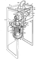
- the boiler shown essentially comprises a backrest 2 for its attachment to the mounting wall of the room, and side frames 3 having large openings, these elements 2 and 3 constituting the frame 1 of the device.
- a horizontal plate 4 which is also supported by an angle 5 arranged transversely to the frames 3.
- This horizontal plate 4 slightly offset laterally relative to the axis of the frame 1 supports a heat exchanger 6 consisting of a cylindrical layer of water tubes 7 arranged vertically and interconnected by a lower circular collector 8 and by an upper circular collector 9, these tubes thus forming a cylindrical combustion chamber 10.
- the heat exchanger 6 is provided with a central opening 11 at its upper part, on the other hand it is closed by a bottom at its lower part.
- the horizontal plate 4 comprises at the base of the central inlet orifice 11 of the exchanger 6, a cutout 12 for, on the one hand, the positioning in said exchanger 6 of a burner 13, for example of the torch type, the flame is oriented downwards and on the other hand the passage of the pipes 14 for the inlet and outlet of water from the exchanger.
- the heat exchanger 6 is wrapped in a waterproof and anti-noise shell 15 of substantially oval shape which is removably supported under the horizontal plate 4 by clips 16.
- This waterproof shell 15, for example made of molded plastic or produced semi-rigid or flexible analog, present on its upper edge which is applied under the horizontal plate 4 a groove 24 in which is placed an O-ring 25 to ensure sealing.
- an orifice 26 In the bottom of the sealed shell 15 is provided an orifice 26 for the evacuation of condensates.
- the sealed shell 15 is offset laterally in the frame 1 and leaves on the side a space for the possible mounting of a sanitary water exchanger, not shown.
- An upper cover 17 which closes the frame serves as a support for the conduit 19 for the admission of fresh air inside which and coaxially is arranged in known manner another conduit 18 of smaller diameter for the evacuation of the burnt gases.
- an air-gas mixing chamber 27 which is - by its upper part -, directly in communication with the duct 19 for admitting fresh air by means of said distribution box 20 and - by a lateral face -, connected to the inlet orifice 28 of a fan 29 by means of a tube 30.
- a gas injector 31 disposed horizontally in the axis of the tube 30 allows the injection of gas and its mixture with air in said tube.
- the fan 29 is mounted under the upper cover 17 so that its outlet pipe 32 directly connected to the burner 13 is located in the axis of the central inlet orifice 11 of the heat exchanger 6.
- the movement of air and gas inside these different elements is therefore ensured by the fan 29.
- the fresh air is sucked in from the outside through the duct 19 and the distribution box 20 into the mixing chamber 27 to form with the gas in said chamber a combustible mixture which penetrates through the tube 30 into the fan 29 before being injected through the pipe 32 into the burner 13 where it ignites.
- the products of combustion pass through the cylindrical layer of water tubes 7, then are collected in the sealed shell 15 and are then discharged towards the outside by the connection tube 22 and the evacuation duct 18.
- the shell 15 is produced in the form of a parallelepipedal box also covering the orifice 23 for the outlet of the combustion products.
- the device thus described by way of nonlimiting example is therefore of reduced size while allowing easy accessibility of the various mechanisms which facilitates assembly, disassembly and maintenance operations.
- these mechanisms being properly ventilated by the ambient atmosphere and thermally insulated from the hot part by the sealed shell, can be made of common material, in particular with parts of plastic material.
Landscapes
- Engineering & Computer Science (AREA)
- Physics & Mathematics (AREA)
- Thermal Sciences (AREA)
- Chemical & Material Sciences (AREA)
- Combustion & Propulsion (AREA)
- Mechanical Engineering (AREA)
- General Engineering & Computer Science (AREA)
- Housings, Intake/Discharge, And Installation Of Fluid Heaters (AREA)
- Combustion Of Fluid Fuel (AREA)
- Processing Of Solid Wastes (AREA)
- Gas Burners (AREA)
- Resistance Heating (AREA)
Priority Applications (1)
| Application Number | Priority Date | Filing Date | Title |
|---|---|---|---|
| AT83401916T ATE20774T1 (de) | 1982-10-05 | 1983-09-30 | Gasdichter kessel mit zwangsabzug. |
Applications Claiming Priority (2)
| Application Number | Priority Date | Filing Date | Title |
|---|---|---|---|
| FR8216664 | 1982-10-05 | ||
| FR8216664A FR2534005A1 (fr) | 1982-10-05 | 1982-10-05 | Agencement d'une chaudiere etanche a gaz a tirage force |
Publications (2)
| Publication Number | Publication Date |
|---|---|
| EP0105805A1 EP0105805A1 (fr) | 1984-04-18 |
| EP0105805B1 true EP0105805B1 (fr) | 1986-07-16 |
Family
ID=9277976
Family Applications (1)
| Application Number | Title | Priority Date | Filing Date |
|---|---|---|---|
| EP83401916A Expired EP0105805B1 (fr) | 1982-10-05 | 1983-09-30 | Agencement d'une chaudière étanche à gaz à tirage forcé |
Country Status (7)
| Country | Link |
|---|---|
| US (1) | US4491092A (2) |
| EP (1) | EP0105805B1 (2) |
| JP (1) | JPS59100338A (2) |
| AT (1) | ATE20774T1 (2) |
| DE (1) | DE3364530D1 (2) |
| ES (1) | ES8405500A1 (2) |
| FR (1) | FR2534005A1 (2) |
Families Citing this family (7)
| Publication number | Priority date | Publication date | Assignee | Title |
|---|---|---|---|---|
| FR2577309B1 (fr) * | 1985-02-13 | 1987-04-17 | Sdecc | Chaudiere a gaz modulante du type etanche a condensation, a fonctionnement silencieux. |
| US5435716A (en) * | 1991-12-30 | 1995-07-25 | Bowin Designs Pty Ltd | Gas-fired heaters with burners having a substantially sealed combustion chamber |
| US6019069A (en) * | 1991-12-30 | 2000-02-01 | Bowin Technology Pty. Ltd. | Gas-fired heaters with burners which operate without secondary air and have a substantially sealed combustion chamber |
| JPH07505701A (ja) * | 1991-12-30 | 1995-06-22 | ボウウィン テクノロジー ピーティワイ リミテッド | 二次空気を使用せずに運転されるバーナを有するガス点火型ヒータ |
| US5632236A (en) * | 1991-12-30 | 1997-05-27 | Bowin Technology Pty. Ltd. | Gas-fired heaters with burners which operate without secondary air and have a substantially sealed combustion chamber |
| CN104110858B (zh) * | 2013-07-24 | 2017-10-27 | 芜湖美的厨卫电器制造有限公司 | 用于热水器的壳体组件及具有它的热水器 |
| ITAN20130237A1 (it) * | 2013-12-10 | 2015-06-11 | Ariston Thermo Spa | Coperchio per caldaie a condensazione |
Family Cites Families (8)
| Publication number | Priority date | Publication date | Assignee | Title |
|---|---|---|---|---|
| US1923614A (en) * | 1931-04-06 | 1933-08-22 | Clarkson Thomas | Burner control system |
| FR2327496A1 (fr) * | 1973-12-13 | 1977-05-06 | Saunier Duval | Agencement et montage de l'enceinte etanche et de la chambre de combustion d'une chaudiere etanche a gaz a tirage force |
| DE2837004A1 (de) * | 1978-08-24 | 1980-03-06 | Bernstein Lennart | Verfahren und heizungskessel zum erwaermen des heizwassers in einer warmwasser-zentralheizungsanlage, insbesondere fuer ein- und mehrfamilienwohnhaeuser |
| US4287857A (en) * | 1979-09-11 | 1981-09-08 | Leo Schnitzer | Burner-boiler combination and an improved burner construction therefor |
| FR2499223B1 (fr) * | 1979-11-23 | 1985-06-28 | Landreau Andre | Chaudiere, notamment pour installation de chauffage |
| JPS5850978Y2 (ja) * | 1980-09-16 | 1983-11-21 | 飯田工業株式会社 | 木工用鉋盤における鉋刃の刃先位置調節機構 |
| FR2493483A1 (fr) * | 1980-10-31 | 1982-05-07 | Sdecc | Chambre etanche d'echangeur de chaleur a nappe de tubes d'eau longitudinaux disposes concentriquement a un bruleur central |
| EP0052055B1 (fr) * | 1980-11-07 | 1984-07-25 | SAUNIER DUVAL EAU CHAUDE CHAUFFAGE S.D.E.C.C. - Société anonyme | Chaudière étanche à échangeur cylindrique |
-
1982
- 1982-10-05 FR FR8216664A patent/FR2534005A1/fr active Granted
-
1983
- 1983-09-30 EP EP83401916A patent/EP0105805B1/fr not_active Expired
- 1983-09-30 DE DE8383401916T patent/DE3364530D1/de not_active Expired
- 1983-09-30 AT AT83401916T patent/ATE20774T1/de active
- 1983-10-04 ES ES526236A patent/ES8405500A1/es not_active Expired
- 1983-10-04 US US06/539,054 patent/US4491092A/en not_active Expired - Lifetime
- 1983-10-05 JP JP58186650A patent/JPS59100338A/ja active Granted
Also Published As
| Publication number | Publication date |
|---|---|
| DE3364530D1 (en) | 1986-08-21 |
| ES526236A0 (es) | 1984-06-16 |
| FR2534005A1 (fr) | 1984-04-06 |
| JPS59100338A (ja) | 1984-06-09 |
| ES8405500A1 (es) | 1984-06-16 |
| FR2534005B1 (2) | 1985-02-15 |
| US4491092A (en) | 1985-01-01 |
| JPH0442585B2 (2) | 1992-07-13 |
| EP0105805A1 (fr) | 1984-04-18 |
| ATE20774T1 (de) | 1986-08-15 |
Similar Documents
| Publication | Publication Date | Title |
|---|---|---|
| FR2804496A1 (fr) | Bruleur a gaz a multiples couronnes de flammes | |
| EP0105805B1 (fr) | Agencement d'une chaudière étanche à gaz à tirage forcé | |
| EP0032203B1 (fr) | Capteur de chaleur pouvant être installé notamment dans une cheminée domestique et procédé pour porter à une température plus élevée un fluide tel que de l'eau | |
| EP0016700B1 (fr) | Dispositif d'évacuation des gaz brûlés et d'admission d'air frais pour appareils étanches à gaz | |
| FR2461198A1 (fr) | Installation de chauffage, notamment au gaz, du type etanche | |
| EP0052055B1 (fr) | Chaudière étanche à échangeur cylindrique | |
| FR2512932A1 (fr) | Perfectionnements aux cheminees a foyer ouvert | |
| EP0051516B1 (fr) | Chambre étanche d'échangeur de chaleur à nappe de tubes d'eau longitudinaux disposés concentriquement à un brûleur central | |
| EP0323502B1 (fr) | Dispositif formant bruleur a gaz, notamment pour appareil de chauffage. | |
| FR2464437A1 (fr) | Chaudiere dont le bruleur est forme par une paroi de la chambre de melange | |
| FR2951809A1 (fr) | Equipement pour le passage d'un conduit d'evacuation de fumee connecte a une chaudiere, au travers d'une lumiere d'un boisseau de cheminee maconne | |
| EP0499557B1 (fr) | Brûleur compact en fonte du type à prémélange total | |
| EP1018584A1 (fr) | Conduit de cheminée ainsi que boisseau de cheminée utilisable pour réaliser un tel conduit | |
| FR2560359A1 (fr) | Perfectionnements a un dispositif de chauffage a bruleur a gaz et tube radiant | |
| EP0058099A1 (fr) | Assemblage étanche pour chaudière à tirage forcé | |
| FR2493968A1 (fr) | Chaudiere etanche a echangeur cylindrique | |
| FR2504659A1 (fr) | Dispositif de securite pour chambre de combustion a paroi souple | |
| FR2660050A1 (fr) | Chaudiere murale a gaz du type etanche et a circulation d'air forcee pour usage domestique. | |
| FR2641062A3 (2) | ||
| FR2577019A1 (fr) | Installation de chauffage pour cheminee a foyer ouvert et tirage inverse | |
| FR2535026A1 (fr) | Chaudiere a bois ou autres materiaux combustibles solides | |
| FR3048072A1 (fr) | Appareil de chauffage domestique | |
| BE361390A (2) | ||
| FR3095500A1 (fr) | Appareil de cuisson | |
| FR2677739A3 (en) | Heating appliance structure for premises |
Legal Events
| Date | Code | Title | Description |
|---|---|---|---|
| PUAI | Public reference made under article 153(3) epc to a published international application that has entered the european phase |
Free format text: ORIGINAL CODE: 0009012 |
|
| AK | Designated contracting states |
Designated state(s): AT BE CH DE GB IT LI LU NL |
|
| 17P | Request for examination filed |
Effective date: 19840927 |
|
| GRAA | (expected) grant |
Free format text: ORIGINAL CODE: 0009210 |
|
| AK | Designated contracting states |
Kind code of ref document: B1 Designated state(s): AT BE CH DE GB IT LI LU NL |
|
| REF | Corresponds to: |
Ref document number: 20774 Country of ref document: AT Date of ref document: 19860815 Kind code of ref document: T |
|
| REF | Corresponds to: |
Ref document number: 3364530 Country of ref document: DE Date of ref document: 19860821 |
|
| ITF | It: translation for a ep patent filed | ||
| PLBE | No opposition filed within time limit |
Free format text: ORIGINAL CODE: 0009261 |
|
| STAA | Information on the status of an ep patent application or granted ep patent |
Free format text: STATUS: NO OPPOSITION FILED WITHIN TIME LIMIT |
|
| 26N | No opposition filed | ||
| REG | Reference to a national code |
Ref country code: LU Ref legal event code: CNA Free format text: 7830 26 18, RUE D'ALSACE, F-92400 COURBEVOIE |
|
| ITTA | It: last paid annual fee | ||
| EPTA | Lu: last paid annual fee | ||
| PGFP | Annual fee paid to national office [announced via postgrant information from national office to epo] |
Ref country code: LU Payment date: 19940901 Year of fee payment: 12 |
|
| PGFP | Annual fee paid to national office [announced via postgrant information from national office to epo] |
Ref country code: BE Payment date: 19940922 Year of fee payment: 12 |
|
| PGFP | Annual fee paid to national office [announced via postgrant information from national office to epo] |
Ref country code: AT Payment date: 19940927 Year of fee payment: 12 |
|
| PGFP | Annual fee paid to national office [announced via postgrant information from national office to epo] |
Ref country code: CH Payment date: 19940930 Year of fee payment: 12 |
|
| PG25 | Lapsed in a contracting state [announced via postgrant information from national office to epo] |
Ref country code: LU Free format text: LAPSE BECAUSE OF NON-PAYMENT OF DUE FEES Effective date: 19950930 Ref country code: LI Effective date: 19950930 Ref country code: CH Effective date: 19950930 Ref country code: BE Effective date: 19950930 Ref country code: AT Effective date: 19950930 |
|
| BERE | Be: lapsed |
Owner name: SAUNIER DUVAL EAU CHAUDE CHAUFFAGE SDECC - S.A. Effective date: 19950930 |
|
| REG | Reference to a national code |
Ref country code: CH Ref legal event code: PL |
|
| PGFP | Annual fee paid to national office [announced via postgrant information from national office to epo] |
Ref country code: GB Payment date: 19960923 Year of fee payment: 14 |
|
| PGFP | Annual fee paid to national office [announced via postgrant information from national office to epo] |
Ref country code: DE Payment date: 19960928 Year of fee payment: 14 |
|
| PGFP | Annual fee paid to national office [announced via postgrant information from national office to epo] |
Ref country code: NL Payment date: 19960930 Year of fee payment: 14 |
|
| PG25 | Lapsed in a contracting state [announced via postgrant information from national office to epo] |
Ref country code: GB Free format text: LAPSE BECAUSE OF NON-PAYMENT OF DUE FEES Effective date: 19970930 |
|
| PG25 | Lapsed in a contracting state [announced via postgrant information from national office to epo] |
Ref country code: NL Free format text: LAPSE BECAUSE OF NON-PAYMENT OF DUE FEES Effective date: 19980401 |
|
| GBPC | Gb: european patent ceased through non-payment of renewal fee |
Effective date: 19970930 |
|
| NLV4 | Nl: lapsed or anulled due to non-payment of the annual fee |
Effective date: 19980401 |
|
| PG25 | Lapsed in a contracting state [announced via postgrant information from national office to epo] |
Ref country code: DE Free format text: LAPSE BECAUSE OF NON-PAYMENT OF DUE FEES Effective date: 19980603 |