EP0105675A2 - Restraining fittings - Google Patents
Restraining fittings Download PDFInfo
- Publication number
- EP0105675A2 EP0105675A2 EP83305638A EP83305638A EP0105675A2 EP 0105675 A2 EP0105675 A2 EP 0105675A2 EP 83305638 A EP83305638 A EP 83305638A EP 83305638 A EP83305638 A EP 83305638A EP 0105675 A2 EP0105675 A2 EP 0105675A2
- Authority
- EP
- European Patent Office
- Prior art keywords
- restraining
- fitting according
- track
- protrusions
- channel
- Prior art date
- Legal status (The legal status is an assumption and is not a legal conclusion. Google has not performed a legal analysis and makes no representation as to the accuracy of the status listed.)
- Withdrawn
Links
Images


Classifications
-
- B—PERFORMING OPERATIONS; TRANSPORTING
- B64—AIRCRAFT; AVIATION; COSMONAUTICS
- B64C—AEROPLANES; HELICOPTERS
- B64C1/00—Fuselages; Constructional features common to fuselages, wings, stabilising surfaces or the like
- B64C1/18—Floors
- B64C1/20—Floors specially adapted for freight
Definitions
- the present invention relates to hold-down or restraining fittings and, in particular, relates to a restraining fitting and a cooperating track member that does not require displacement of the restraining fitting on the device affixed thereto once inserted in the track member for retainment.
- restraining devices e.g. tie-down devices, hold-down fittings and tracks and/or anchors are in use today on aircraft to convert their internal carrying space from passenger seats to cargo bays in order to meet the varying demands of customers.
- the ideal type of restraining or hold-down device should be flexible and easily removable so that conversion from a cargo hold-down arrangement to placement of passenger seats can be made with ease.
- Various types of mechanisms, devices, shelving, chairs, etc. are required to be installed and removed as necessary. In devices utilized at the present time, it frequently becomes necessary and is convenient to use a track member which is permanently affixed to the floor, wall and/or ceiling of the interior carrying space.
- a track provided with a longitudinal undercut channel and a plurality of bore holes is one of the most popular in use today.
- This type of track permits many different types of restraining devices to be inserted into the bore holes provided. The devices are moved in the undercut channel and, thereby, are restrained from removal from the track because a portion of the restraining device is disposed beneath the undercut channel lip.
- One of the shortcomings of the devices presently in use requires that the hold down device be inserted into the bore holes provided in the longitudinal undercut channel provided in the track and then moved to the area between bore holes in order to be captured by the lip of the undercut channel.
- This requires that once an object, such as a chair having its legs or mounting associated therewith, is positioned for installation by inserting its mounting into a cooperating bore hole, it must be moved to place it in a restrained position.
- the instant invention overcomes the known shortcomings and provides a relatively simple means to accomplish a positive lock to an object once installed in a mating track, provides a visual indication when the lock has been accomplished and, furthermore, does not require that an object, once inserted in the track, be moved in order to obtain its restrained position.
- a restraining fitting 10 disposed in a mating or cooperating track 12 which may be affixed to any .flat surface in or on a vehicle such as an airplane, automobile, ship, etc.
- the upper member 16 of the restraining fitting 10 is provided with a restraining device such as stud 18 adapted to be received into a threaded aperture 20 provided in the top of upper member 16.
- a threaded stud 18 is shown in the preferred embodiment, it is well known by those knowledgeable in the art that upper member 16 may be formed directly with other types of restraining devices as an integral part thereof.
- Threaded stud 18 may then receive a ring device 22 which has a lower threaded portion 24 that cooperates with threaded stud 18 and, when tightened in position, permits the swivel ring 26 to accept a tie-down belt or webbing 28 therein for the purpose of holding down cargo or other items to the surface 14, as will be explained hereinafter.
- the upper member 16 is provided with a T-shaped channel 30 disposed longitudinally and a plurality of downwardly depending, spaced apart, cylindrically shaped protrusions 32 and 34.
- Protrusion 32 is cut in half merely for convenience in explaining the operation of the present embodiment. It is to be understood that a plurality of these protrusions are to be utilized and they will be spaced preferably so that the distance between centers of the protrusions is equal to the diameter of the protrusions.
- the number of protrusions employed depends upon the length of the upper member utilized and the forces that they are to restrain and, of course, are to be considered in the design, of an overall system.
- the height of the protrusion 32 and scalloped 34 is preferably equal to or slightly greater than the/lip portion 36 provided by the undercut channel 56 on the mating or cooperating track member 12. and the diameter of the protrusions 32 and 34 should be slightly less than the diameter provided in the bore holes 38, 40, and 42 provided in the track 12.
- circularly shaped protrusions and bore holes are preferred, any mating shapes or configurations may be utilized.
- a lower member 44 is provided with a T-shaped portion 46 that is designed to be slidably retained within the T-shaped channel 30 provided in the upper portion 16.
- the lower portion 48 of the lower member 44 is provided at the distal end thereof with a series of circularly-shaped protrusions 50, 52 and 54 having a diameter essentially equal to the diameter of protrusions 32 and 34 provided on the' underside of upper member 16.
- the height of protrusions 50, 52 and 54 is slightly less than the longitudinal undercut inverted T-shaped channel 56 provided in track 12 with which it is to cooperate as will be explained hereinafter.
- the lower portion 48 extends longitudinally and protrusions 50, 52 and 54 are spaced thereon in the same manner as protrusions 32 and 34 are spaced on upper member 16.
- protrusions 50 and 54 have been cut in half for convenience, it is understood that a plurality of preferably circularly shaped protrusions as shown in 52 are to be included.
- Lower portion 48 extends through the channel opening 58 provided in channel 56 and in channel opening 60 provided in channel 30 in the upper member 16, thereby providing a severing of protrusions 32 and 34 into segments which is shown in Figure 3.
- Track member 12 is provided with mounting holes 62, 6 4 , 66 and 68 into which are inserted screws or rivets 70, 72, 74 and 76 in order to affix the track member 12 to any flat surface.
- the number of mounting holes utilized and the screw size to be utilized depends upon the load to be restrained and is a matter of design choice.
- the apertures 38, 40 and 42 are slightly larger in diameter than the diameter of the protrusions 32 and 34 and protrusions 50, 52 and 54.
- Protrusions 32 and 34 when received by the apertures 38, 40 and 42, maintain the upper member in position, preventing any movement in the longitudinal direction and by movement of the lower member 44 in the direction of arrow 80, causing displacement of protrusions 52 from 34 and 50 from 32 will restrain the upper member from being removed.from.the track 12 since protrusions 50 and 52 will engage the lip portion 36 provided in the track 12, as is shown in Figure 3. Movement of lower member 44 in the direction of arrow 82 will cause alignment of protrusions 34 and 52, 32 and 50, thereby permitting the upper member 16 to be removed together with the lower member 44 from the track 12. The position of the protrusions is clearly shown by comparing Figure 2 to Figure 3, and their location relative to the cooperating track 12.
- FIG 4 there is shown an exploded view of the upper member 16 and the lower member 44 which is received therein, including the mechanical arrangement for the detent mechanism which provides for a positive indexing of the lower member 44 when it is moved from the locked position, in the direction of arrow 82, to the unlocked position shown in Figure 2 and conversely when it is moved in the direction of arrow 80 to return to the locked position as shown in Figure 3.
- a threaded aperture 84 is centrally disposed in protrusion 52 entering and going clear through the lower member 44, perpendicular to the longitudinal axis thereof.
- the threaded aperture 84 has inserted therein a detent ball 86, a coil spring 88 and headless screw 90 which is utilized to set the pressure on the detent ball 86.
- a set screw 92 is utilized to maintain screw 90 in position and prevent it from working loose under vibration conditions.
- An elongated bore hole 94 is provided in the upper portion of channel 30. Bore 94 is provided with two detent depressions 96 and 98 into which detent ball 86 enters, indexing the locked and unlocked position when lower member 44 is moved or translated along the longitudinal axis of the lower member 44. Thus, once upper member. 16 has been positioned on track 12, it remains in position and lower member 44 is the mechanism that affects the locking of the restraining fitting 10.
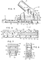
- FIG. 5 wherein there is shown an alternative embodiment 100 of a restraining fitting which has its upper portion fabricated from two members 102 and 104, having a mating T-shaped channel 106 and protrusion 108 rigidly held together by conventional force fit techniques (see - Figure 7).
- Member 102 is preferably U-shaped and provided with a pair of apertures 110 and 112 into which a retaining pin 114 may be inserted.
- Retaining pin 114 is provided with a locking arm 116 to prevent inadvertent removal of the pin once placed in position to retain a device such as the leg of a chair 118 which may be provided with a corresponding aperture to align with apertures 110 and l12 or may receive the vertical portion of a shelf, or any other device, which is to be held in position.
- a device such as the leg of a chair 118 which may be provided with a corresponding aperture to align with apertures 110 and l12 or may receive the vertical portion of a shelf, or any other device, which is to be held in position.
- members 102 and 104 are shown as two separate pieces, they may be integrally formed and may also be fabricated as an integral part of chair leg 118 or any other device that is to be restrained. Member 102 may be fabricated together with member 104 in an infinite variety of assemblies which may be specifically adapted to the articles to be restrained.
- the lower or sliding member 120 of restraining fitting 100 is fabricated identical to the lower member 44 as described in conjunction with the embodiment disclosed in Figures 1 through 4. The only exception being that additional protrusions are incorporated herein since the restraining member 100 is larger in size and is suitable for restraining heavier loads. These protrusions 122, 124, 126, and 128 are shown in their locked position in Figure 5.
- Figure 6 shows a top plan view of the protrusions relative to apertures 130, 132, 134, and 136.
- protrusions 122, 124, 126 and 128 are displaced relative to apertures 130, 132, 134 and 136 so that the lip portions 138, 140, 142 and 144 of track 12 prevent the removing of the restraining fitting 100 from the track 12 in this position, while protrusions 146 (see Figure 7) positioned in each of the apertures 130, 132, 134 and 136 prevent lateral or longitudinal movement of the restraining fitting along longitudinal axis 150.
- the protrusions provided on the underside thereof are sloped in an upwardly direction toward the-longitudinal axis as shown in Figure 7 and the cooperating upper surface 148 of protrusion 128 is also provided with a sloping surface, sloping downwardly away from the longitudinal axis to further reduce any frictional engagement between the two surfaces.
- the lower or sliding member 120 is provided with an extending portion 152 which is readily accessible to an individual who is to change the position of the sliding member from its unlocked to its locked state.
- the upper surface 154 (shown in Figure 5) of the extending portion 152- may be provided with indicia thereon such as, for example, the word "locked” and a color, for example, green, making it apparent, with merely a cursory review, the state of the restraining fitting 100.
- the sliding member 120 When moved from the position shown in Figure 5 in the direction of arrow 156, the sliding member 120 will be moved to the position shown by dotted line 158 whereupon the extending portion 160 may be provided on the surface 162 with indicia thereon such as "unlocked” and be colored red, so that a cursory review thereof will readily indicate this condition.
- a detent mechanism such as that described in conjunction with the embodiment disclosed in Figure 4 may also be incorporated herein to provide a positive indication when the slide 120 is moved from the locked to the unlocked position.
- the detent mechanism 164 is shown in Figure 8 and includes a set screw 166, spring 168, and detent ball 170.
- a locking device 172 provided in the extending portion 152 of the lower or sliding member 120.
- the restraining fitting 100 is in its locked position and, therefore, a spring loaded plunger 174 protrudes from a bore hole 176 provided in sliding member 120.
- a spring 178 urges the plunger 174 upwardly and is retained by a shoulder provided in the bore hole 176.
- Spring 178 is retained in the bore hole by a set screw 180, of the conventional type.
- the plunger 174 protrudes upwardly and comes into contact with the edge 182 of member 104 thereby preventing any movement of sliding member 120 in the direction of arrow 82 and preventing any unintentional movement from the locked to the unlocked position.
- an individual will be required to depress plunger 174 beneath the surface 154 of the sliding member 120 and then exert pressure in the direction of arrow 82.
- a similar locking mechanism may be provided on the opposite end of sliding member 120 retaining the sliding member 120 in its unlocked position until released in the same manner.
- Mechanism 184 includes a ring pull member 186 which is affixed to the distal end of a locking pin 188 which is provided with a detent groove 190 that is part of a slot 192 provided proximate the other end thereof. Pin 188 is received by an aperture 194 provided in the sliding member 120 which is positioned to coincide with a slotted groove 196 provided in member 104.
- the sliding member 120 is also provided with a spring loaded detent mechanism 198 which is seen to include a detent ball 200, spring 202 and set screw 204 which is positioned transverse to the pin 188.
- aperture 196 is an elongated groove
- the sliding member may move freely from the locked to the unlocked position, however, on the far side. of member 104, only two holes 206 and 208 are provided on the far side (see Figure 10). These holes are adapted to receive the distal end of pin 188 when in either the locked or the unlocked position and, therefore, inadvertent movement from one position to the other is prevented.
- ring pull 186 is pulled in the 11 direction of arrow 210 to remove pin 188 from hole 206.
- the sliding member 120 may then be moved to the unlocked position in the direction of arrow 212 taking with it pin 188.
- pin 188 When the unlocked position is reached, pin 188 may be pushed in the direction of arrow 214 causing pin 188 to be received by hole 208, thereby locking the restraining fitting 100 in the unlocked position.
- a restraining fitting which may be positioned to cooperate with a mating track member, may be held onto the track member by the translation or movement of a sliding member and locked in position with ease, providing a visual indication of the position in which the device is disposed.
- the track member be fabricated in bulk and cut to specified lengths.
- the restraining portions may be fabricated in different modular constructions to cooperate with the track members, thereby permitting the invention to be utilized in numerous configurations for different applications.
Abstract
Description
- The present invention relates to hold-down or restraining fittings and, in particular, relates to a restraining fitting and a cooperating track member that does not require displacement of the restraining fitting on the device affixed thereto once inserted in the track member for retainment.
- Many different types of restraining devices, e.g. tie-down devices, hold-down fittings and tracks and/or anchors are in use today on aircraft to convert their internal carrying space from passenger seats to cargo bays in order to meet the varying demands of customers. The ideal type of restraining or hold-down device should be flexible and easily removable so that conversion from a cargo hold-down arrangement to placement of passenger seats can be made with ease. Various types of mechanisms, devices, shelving, chairs, etc. are required to be installed and removed as necessary. In devices utilized at the present time, it frequently becomes necessary and is convenient to use a track member which is permanently affixed to the floor, wall and/or ceiling of the interior carrying space.
- Although the discussion herein is generally related to changes in aircraft interiors, the restraining fittings disclosed herein are ideally suitable for use in other types of vehicles such as automobiles, vans, ships, etc.. Various types of permanent tracks or anchors have been utilized over the years. A track provided with a longitudinal undercut channel and a plurality of bore holes is one of the most popular in use today. This type of track permits many different types of restraining devices to be inserted into the bore holes provided. The devices are moved in the undercut channel and, thereby, are restrained from removal from the track because a portion of the restraining device is disposed beneath the undercut channel lip. This approach has been found to be successful because very little restrictions are place on the installation of the track and-the track is suitable for receiving any number of different types of restraining fittings, anchors, or hold-down devices, etc which may be used in conjunction with tie-down straps, webbing, etc.
- One of the shortcomings of the devices presently in use requires that the hold down device be inserted into the bore holes provided in the longitudinal undercut channel provided in the track and then moved to the area between bore holes in order to be captured by the lip of the undercut channel. This requires that once an object, such as a chair having its legs or mounting associated therewith, is positioned for installation by inserting its mounting into a cooperating bore hole, it must be moved to place it in a restrained position. Generally, there is no visual indication when the object (chair) is moved to the restrained or locked position or that it may be removed by exerting an upwardly directed force. This may cause numerous problems because installation personnel may forget to move the object to its locked position and, therefore, the object is free to come loose vibration or when vertical forces are exerted upon it. Additional time, care and inspection is required to insure that the installation of the restraining devices have been made properly. Moreover, a positive lock is not provided when the object has been placed in its restrained position, nor is there a visual indication that the restrained position has been accomplished.
- The instant invention overcomes the known shortcomings and provides a relatively simple means to accomplish a positive lock to an object once installed in a mating track, provides a visual indication when the lock has been accomplished and, furthermore, does not require that an object, once inserted in the track, be moved in order to obtain its restrained position.
- Therefore, it is an object of the present invention to provide a reliable restraining fitting which may be easily installable in a cooperating track.
- It is another object of the present invention to provide a restraining fitting suitable for numerous applications with ease of installation and positive locking.
- It is a further object of the. present invention to provide a restraining fitting which, when installed into a mating track and locked into position, will provide a visual indication to an observer with a cursory review.
- It is yet another object of the present invention to provide a restraining fitting suitable for use with a mating track that provides a positive detent when it is in its locked position and, furthermore, requires a release to be changed from the locked to the unlocked position.
- It is yet another object of the present invention to provide a restraining fitting suitable for use with objects to be affixed to a mating track which may be positioned upon installation and not moved to provide a locking or restraining mode.
- The foregoing and other objects and advantages will appear from the description to follow. In the description, reference is made to the accompanying drawing which forms a part hereof, and in which is shown by way of illustration specific embodiments in which the invention may be practiced. These embodiments will be described in sufficient detail to enable those skilled in the art to practice the invention, and'it is to be understood that other embodiments may be utilized and that structural changes may be made without departing from the scope of the invention. The following detailed description is, therefore, not to be taken in a limiting sense, and the scope of the present invention is best defined by the appended claims.
- In order that the invention may be more fully understood, it will now be described, by way of example, with reference to the accompanying drawing in which:
- Figure 1 is a side view, .in elevation, partially broken away, of a restraining fitting in its unlocked posision, according to the principles of the instant invention, and inserted in a mating or cooperating track member;
- Figure 2 is an isometric exploded view of the restraining fitting in its unlocked position just prior to insertion into a cooperating track;
- Figure 3 is an isometric exploded view of the restraining fitting shown in Figure 2 with the protrusion disposed in the locked position;
- Figure 4 is an exploded isometric view showing the detent mechanism utilized in the embodiment disclosed in Figure 1, 2, and 3;
- Figure 5 is a side view, in elevation, partially broken away of an alternative embodiment of a restraining fitting, according to the principles of the present invention, inserted in a mating track member;
- Figure 6 is a top plan view taken along the line 6-6 of Figure 5;
- Figure 7 is a cross-sectional view taken along the line 7-7 of Figure 5;
- Figure 8 is a cross-sectional view taken along the line 8-8 of Figure 5;
- Figure 9 is a side view, in elevation, of the embodiment disclosed in Figure 5, partially broken away, indicating a positive locking mechanism;
- Figure 10 is a top plan view of an alternative embodiment of a detent locking mechanism;
- Figure 11 is a partial side view, in elevation, of the mechanism disclosed in Figure 10; and
- Figure 12 is a cross-sectional view taken along the line 12-12 of Figure 11.
- Referring now to the figures, and in particular to Figures 1, 2, 3 and 4, there is shown a restraining fitting 10 disposed in a mating or cooperating
track 12 which may be affixed to any .flat surface in or on a vehicle such as an airplane, automobile, ship, etc.. Theupper member 16 of therestraining fitting 10 is provided with a restraining device such asstud 18 adapted to be received into a threadedaperture 20 provided in the top ofupper member 16. Although a threadedstud 18 is shown in the preferred embodiment, it is well known by those knowledgeable in the art thatupper member 16 may be formed directly with other types of restraining devices as an integral part thereof. Threadedstud 18 may then receive aring device 22 which has a lower threadedportion 24 that cooperates with threadedstud 18 and, when tightened in position, permits theswivel ring 26 to accept a tie-down belt or webbing 28 therein for the purpose of holding down cargo or other items to thesurface 14, as will be explained hereinafter. - The
upper member 16 is provided with a T-shaped channel 30 disposed longitudinally and a plurality of downwardly depending, spaced apart, cylindrically shapedprotrusions Protrusion 32 is cut in half merely for convenience in explaining the operation of the present embodiment. It is to be understood that a plurality of these protrusions are to be utilized and they will be spaced preferably so that the distance between centers of the protrusions is equal to the diameter of the protrusions. The number of protrusions employed depends upon the length of the upper member utilized and the forces that they are to restrain and, of course, are to be considered in the design, of an overall system. The height of theprotrusion 32 and scalloped 34 is preferably equal to or slightly greater than the/lip portion 36 provided by theundercut channel 56 on the mating or cooperatingtrack member 12. and the diameter of theprotrusions bore holes track 12. Although circularly shaped protrusions and bore holes are preferred, any mating shapes or configurations may be utilized. - A
lower member 44 is provided with a T-shaped portion 46 that is designed to be slidably retained within the T-shaped channel 30 provided in theupper portion 16. Thelower portion 48 of thelower member 44 is provided at the distal end thereof with a series of circularly-shaped protrusions protrusions upper member 16. The height ofprotrusions shaped channel 56 provided intrack 12 with which it is to cooperate as will be explained hereinafter. Thelower portion 48 extends longitudinally andprotrusions protrusions upper member 16. The number of protrusions provided here again are determined in the same manner asprotrusions protrusions Lower portion 48 extends through thechannel opening 58 provided inchannel 56 and inchannel opening 60 provided inchannel 30 in theupper member 16, thereby providing a severing ofprotrusions -
Track member 12 is provided with mountingholes track member 12 to any flat surface. The number of mounting holes utilized and the screw size to be utilized depends upon the load to be restrained and is a matter of design choice. Theapertures protrusions protrusions apertures lower member 44 in the direction ofarrow 80, causing displacement ofprotrusions 52 from 34 and 50 from 32 will restrain the upper member from being removed.from.thetrack 12 sinceprotrusions lip portion 36 provided in thetrack 12, as is shown in Figure 3. Movement oflower member 44 in the direction ofarrow 82 will cause alignment ofprotrusions upper member 16 to be removed together with thelower member 44 from thetrack 12. The position of the protrusions is clearly shown by comparing Figure 2 to Figure 3, and their location relative to the cooperatingtrack 12. - Referring now to Figure 4, there is shown an exploded view of the
upper member 16 and thelower member 44 which is received therein, including the mechanical arrangement for the detent mechanism which provides for a positive indexing of thelower member 44 when it is moved from the locked position, in the direction ofarrow 82, to the unlocked position shown in Figure 2 and conversely when it is moved in the direction ofarrow 80 to return to the locked position as shown in Figure 3. Preferably, a threadedaperture 84 is centrally disposed inprotrusion 52 entering and going clear through thelower member 44, perpendicular to the longitudinal axis thereof. The threadedaperture 84 has inserted therein adetent ball 86, acoil spring 88 andheadless screw 90 which is utilized to set the pressure on thedetent ball 86. Preferably aset screw 92 is utilized to maintainscrew 90 in position and prevent it from working loose under vibration conditions. - An
elongated bore hole 94 is provided in the upper portion ofchannel 30.Bore 94 is provided with twodetent depressions detent ball 86 enters, indexing the locked and unlocked position whenlower member 44 is moved or translated along the longitudinal axis of thelower member 44. Thus, once upper member. 16 has been positioned ontrack 12, it remains in position andlower member 44 is the mechanism that affects the locking of the restraining fitting 10. - Referring now to Figure 5, wherein there is shown an
alternative embodiment 100 of a restraining fitting which has its upper portion fabricated from twomembers channel 106 andprotrusion 108 rigidly held together by conventional force fit techniques (see -Figure 7).Member 102 is preferably U-shaped and provided with a pair ofapertures retaining pin 114 may be inserted. Retainingpin 114 is provided with alocking arm 116 to prevent inadvertent removal of the pin once placed in position to retain a device such as the leg of achair 118 which may be provided with a corresponding aperture to align withapertures 110 and l12 or may receive the vertical portion of a shelf, or any other device, which is to be held in position. It is to be understood that althoughmembers chair leg 118 or any other device that is to be restrained.Member 102 may be fabricated together withmember 104 in an infinite variety of assemblies which may be specifically adapted to the articles to be restrained. - The lower or sliding
member 120 of restraining fitting 100 is fabricated identical to thelower member 44 as described in conjunction with the embodiment disclosed in Figures 1 through 4. The only exception being that additional protrusions are incorporated herein since the restrainingmember 100 is larger in size and is suitable for restraining heavier loads. Theseprotrusions apertures protrusions apertures lip portions track 12 prevent the removing of the restraining fitting 100 from thetrack 12 in this position, while protrusions 146 (see Figure 7) positioned in each of theapertures longitudinal axis 150. - In order to provide ease in movement of the lower or sliding
member 120, the protrusions provided on the underside thereof are sloped in an upwardly direction toward the-longitudinal axis as shown in Figure 7 and the cooperatingupper surface 148 ofprotrusion 128 is also provided with a sloping surface, sloping downwardly away from the longitudinal axis to further reduce any frictional engagement between the two surfaces. - As shown in Figure 5, the lower or sliding
member 120 is provided with an extendingportion 152 which is readily accessible to an individual who is to change the position of the sliding member from its unlocked to its locked state. The upper surface 154 (shown in Figure 5) of the extending portion 152- may be provided with indicia thereon such as, for example, the word "locked" and a color, for example, green, making it apparent, with merely a cursory review, the state of the restraining fitting 100. When moved from the position shown in Figure 5 in the direction ofarrow 156, the slidingmember 120 will be moved to the position shown by dottedline 158 whereupon the extendingportion 160 may be provided on thesurface 162 with indicia thereon such as "unlocked" and be colored red, so that a cursory review thereof will readily indicate this condition. - A detent mechanism such as that described in conjunction with the embodiment disclosed in Figure 4 may also be incorporated herein to provide a positive indication when the
slide 120 is moved from the locked to the unlocked position. Thedetent mechanism 164 is shown in Figure 8 and includes aset screw 166,spring 168, anddetent ball 170. - Referring now to Figure 9, there is shown a locking device 172 provided in the extending
portion 152 of the lower or slidingmember 120. As shown in Figure 9, the restraining fitting 100 is in its locked position and, therefore, a spring loaded plunger 174 protrudes from abore hole 176 provided in slidingmember 120. Aspring 178 urges the plunger 174 upwardly and is retained by a shoulder provided in thebore hole 176.Spring 178 is retained in the bore hole by a set screw 180, of the conventional type. Thus, when the slidingmember 120 is in its locked position, the plunger 174 protrudes upwardly and comes into contact with theedge 182 ofmember 104 thereby preventing any movement of slidingmember 120 in the direction ofarrow 82 and preventing any unintentional movement from the locked to the unlocked position. Should it be desirable to unlock the restraining fitting 100, an individual will be required to depress plunger 174 beneath thesurface 154 of the slidingmember 120 and then exert pressure in the direction ofarrow 82. A similar locking mechanism may be provided on the opposite end of slidingmember 120 retaining the slidingmember 120 in its unlocked position until released in the same manner. - An
alternative locking mechanism 184 is disclosed in Figures 10, 11 and 12.Mechanism 184 includes aring pull member 186 which is affixed to the distal end of alocking pin 188 which is provided with adetent groove 190 that is part of aslot 192 provided proximate the other end thereof.Pin 188 is received by anaperture 194 provided in the slidingmember 120 which is positioned to coincide with a slottedgroove 196 provided inmember 104. The slidingmember 120 is also provided with a spring loadeddetent mechanism 198 which is seen to include adetent ball 200,spring 202 and setscrew 204 which is positioned transverse to thepin 188. Sinceaperture 196 is an elongated groove, the sliding member.may move freely from the locked to the unlocked position, however, on the far side. ofmember 104, only twoholes pin 188 when in either the locked or the unlocked position and, therefore, inadvertent movement from one position to the other is prevented. As shown in Figure 10,ring pull 186 is pulled in the 11 direction ofarrow 210 to removepin 188 fromhole 206. The slidingmember 120 may then be moved to the unlocked position in the direction of arrow 212 taking with it pin 188. When the unlocked position is reached, pin 188 may be pushed in the direction ofarrow 214 causingpin 188 to be received byhole 208, thereby locking the restraining fitting 100 in the unlocked position. - Thus, as has been explained hereinbefore, a restraining fitting which may be positioned to cooperate with a mating track member, may be held onto the track member by the translation or movement of a sliding member and locked in position with ease, providing a visual indication of the position in which the device is disposed.
- It is contemplated that the track member be fabricated in bulk and cut to specified lengths. The restraining portions may be fabricated in different modular constructions to cooperate with the track members, thereby permitting the invention to be utilized in numerous configurations for different applications.
- Hereinbefore has been disclosed a simple, efficient, reliable, restraining fitting that may be utilized for a multitude of hold-down applications. It will be understood that various changes in the details, materials, arrangement of parts and operating conditions which have been-herein described and illustrated in order to explain the nature of the invention may be made by those skilled in the art within the principles and scope of the instant invention.
Claims (20)
Applications Claiming Priority (2)
| Application Number | Priority Date | Filing Date | Title |
|---|---|---|---|
| US06/431,837 US4496271A (en) | 1982-09-30 | 1982-09-30 | Restraining fittings |
| US431837 | 1999-11-02 |
Publications (2)
| Publication Number | Publication Date |
|---|---|
| EP0105675A2 true EP0105675A2 (en) | 1984-04-18 |
| EP0105675A3 EP0105675A3 (en) | 1985-05-08 |
Family
ID=23713657
Family Applications (1)
| Application Number | Title | Priority Date | Filing Date |
|---|---|---|---|
| EP83305638A Withdrawn EP0105675A3 (en) | 1982-09-30 | 1983-09-22 | Restraining fittings |
Country Status (3)
| Country | Link |
|---|---|
| US (1) | US4496271A (en) |
| EP (1) | EP0105675A3 (en) |
| IL (1) | IL69883A (en) |
Cited By (23)
| Publication number | Priority date | Publication date | Assignee | Title |
|---|---|---|---|---|
| GB2153215A (en) * | 1984-01-04 | 1985-08-21 | Unwin Limited C N | Furniture anchorages |
| GB2153902A (en) * | 1984-02-10 | 1985-08-29 | Ronald Michael Tipene | Securing devices |
| GB2219493A (en) * | 1988-06-11 | 1989-12-13 | Unwin C N Ltds | Vehicle furniture anchorages |
| GB2238076A (en) * | 1989-10-31 | 1991-05-22 | Short Limited | Captive latch system |
| DE4102273A1 (en) * | 1991-01-26 | 1992-07-30 | Airbus Gmbh | CONNECTING ELEMENT |
| WO1992019496A1 (en) * | 1991-04-27 | 1992-11-12 | Walter Michler | Quick-release fastening device |
| DE4224821A1 (en) * | 1992-07-27 | 1994-02-03 | Electro Pneumatic Int | Fastening device |
| US5310297A (en) * | 1992-08-27 | 1994-05-10 | Federal Express Corporation | Cargo restraint apparatus and system |
| EP0698708A1 (en) * | 1994-08-19 | 1996-02-28 | Meir Avganim | A locking device for arresting a portable object to a stationary object |
| US5692722A (en) * | 1992-12-09 | 1997-12-02 | Lundagaards; Ulf | Locking device |
| DE202007010755U1 (en) | 2007-08-02 | 2008-12-11 | Michler, Walter, Dipl.-Ing. (FH) | Fastening system for the quick detachable fastening of interior components in the cabin of an aircraft |
| DE102007036449A1 (en) | 2007-08-02 | 2009-02-05 | Michler, Walter, Dipl.-Ing. (FH) | Fastening system for the quick detachable fastening of interior components in the cabin of an aircraft |
| WO2014124471A1 (en) * | 2013-02-11 | 2014-08-14 | Ferno-Washington, Inc. | Equipment mounting system |
| US8992238B2 (en) | 2010-07-12 | 2015-03-31 | Ferno-Washington, Inc. | Mounting system having a mounting plate with mounting studs and electrical contacts |
| US9362610B2 (en) | 2012-02-14 | 2016-06-07 | Ferno-Washington, Inc. | Quick antenna attachment system |
| USD776514S1 (en) | 2015-04-21 | 2017-01-17 | Ferno-Washington, Inc. | Mounting adaptor for attachment to a track |
| US9944217B2 (en) | 2013-02-11 | 2018-04-17 | Ferno-Washington, Inc. | Equipment mounting system |
| RU2651308C2 (en) * | 2013-02-11 | 2018-04-19 | Ферно-Вашингтон, Инк. | Self-installing fixing system, equipment support and method, which demonstrates the mounting |
| US10307313B2 (en) | 2013-02-11 | 2019-06-04 | Ferno-Washington, Inc. | Equipment mounting system |
| US10398207B2 (en) | 2014-02-11 | 2019-09-03 | Ferno-Washington, Inc. | Crash-ready, portable, compartmentalization device |
| US10398203B2 (en) | 2014-02-11 | 2019-09-03 | Ferno-Washington, Inc. | Crash-ready, portable, compartmentalization device |
| US10786055B2 (en) | 2014-07-18 | 2020-09-29 | Ferno-Washington, Inc. | Crash-ready, portable, compartmentalization device |
| US11083265B2 (en) | 2014-02-11 | 2021-08-10 | Ferno-Washington, Inc. | Magnetic pouch attachment mechanism with crash stable locking teeth |
Families Citing this family (56)
| Publication number | Priority date | Publication date | Assignee | Title |
|---|---|---|---|---|
| FR2573014B1 (en) * | 1984-11-15 | 1988-04-15 | Lohr Sa | CAR VEHICLE WITH INDIVIDUAL CROSS-CARRIER STRUCTURES SPECIFIC TO EACH WHEEL TRAIN |
| US4602756A (en) * | 1984-11-26 | 1986-07-29 | Chatfield Alan M | Instrument fastening system |
| US4645166A (en) * | 1985-07-31 | 1987-02-24 | Hamco Manufacturing, Inc. | Sofa clamp-quick release clamp for vehicle seats |
| US4708549A (en) * | 1986-05-01 | 1987-11-24 | Ancra Corporation | Rattle-proof anchor fitting for securing loads to retainer track |
| FR2606716B1 (en) * | 1986-11-18 | 1989-02-03 | Lohr Sa | CARRIER UNIT ARM FOR THE SUPPORT OF A VEHICLE BY ITS WHEELS |
| US4867623A (en) * | 1989-02-10 | 1989-09-19 | Aeroquip Corporation | Ring fitting for dunnage track |
| US5190198A (en) * | 1991-03-27 | 1993-03-02 | John A. Bott | Vehicle article carrier |
| US5092722A (en) * | 1991-05-07 | 1992-03-03 | Ferno-Washington, Inc. | Automatically adaptable fastening system for wheeled cots and similar devices |
| US5178346A (en) * | 1991-07-12 | 1993-01-12 | Burns Aerospace Corporation | Track fastener apparatus and assembly |
| US5169091A (en) * | 1991-07-12 | 1992-12-08 | Beroth Michael T | Track fastener apparatus and assembly |
| US5205601A (en) * | 1991-08-30 | 1993-04-27 | Ferno-Washington, Inc. | Ambulance lock |
| US5449132A (en) * | 1992-02-03 | 1995-09-12 | Weber Aircraft, Inc. | Passenger seat rear track fitting |
| US5762296A (en) * | 1992-02-03 | 1998-06-09 | Weber Aircraft, Inc. | Pivot for rear seat track fitting |
| EP0642953B1 (en) * | 1993-09-14 | 1998-04-08 | Jac Products, Inc. | Locking system for adjustable luggage carrier |
| US5609452A (en) * | 1993-12-09 | 1997-03-11 | Satron, Inc. | Cargo track fitting |
| US5674033A (en) * | 1995-05-05 | 1997-10-07 | Ruegg; Thomas Arthur | Vehicle tie-down system for container |
| US6439814B1 (en) * | 1995-11-16 | 2002-08-27 | Wayne G. Floe | Trailer structure & tie-down mechanism |
| US5826766A (en) * | 1997-03-14 | 1998-10-27 | Jac Products, Inc. | Vehicle article carrier |
| US5913559A (en) * | 1997-03-19 | 1999-06-22 | Ferno-Washington, Inc. | Fastening track, cot transport vehicle adapted to secure the fastening track, and cot fastening system incorporating same |
| US6047940A (en) * | 1998-04-13 | 2000-04-11 | Kaplan; Charles | Removably fixed and restorable auditorium seating |
| US6260813B1 (en) * | 2000-01-10 | 2001-07-17 | November Whiskey, Inc. | Aircraft seat track anchor fitting |
| CN1450963A (en) * | 2000-03-15 | 2003-10-22 | 毕享达特莱茵曼研究所 | Connector device for a tensioning or transport strap |
| US6779696B2 (en) * | 2001-10-05 | 2004-08-24 | Jac Products, Inc. | Article carrier having single sided releasable cross bar |
| US6789988B1 (en) * | 2002-02-12 | 2004-09-14 | Ancra International, Llc. | Device for latching a cargo load to a track |
| FR2836962A1 (en) * | 2002-03-08 | 2003-09-12 | Antar Daouk | DEVICE FOR FIXING EQUIPMENT IN AERONAUTICAL TRACKS |
| DE10228434B4 (en) * | 2002-06-26 | 2006-07-06 | Harders, H. Walter | A device for securing cargo on a bed of a tracked vehicle and using the same |
| DE10337746A1 (en) * | 2003-08-13 | 2005-03-17 | Recaro Aircraft Seating Gmbh & Co. Kg | System used especially for fixing airplane seats on the floor of an airplane comprises a fixing rail having openings for receiving catch parts arranged on a rail-shaped fixing part of a catch body |
| US7021596B2 (en) * | 2004-02-11 | 2006-04-04 | Goodrich Corporation | Aircraft seat floor track quick release fitting |
| US6902365B1 (en) * | 2004-02-13 | 2005-06-07 | B E Aerospace, Inc. | Quick-release track fastener |
| US6918722B1 (en) * | 2004-02-27 | 2005-07-19 | Valeda Company Llc | Double plunger track fitting |
| US7637705B2 (en) * | 2004-02-27 | 2009-12-29 | Valeda Company | Track fitting with visual indicia of engagement |
| US7229238B2 (en) * | 2004-03-25 | 2007-06-12 | Valeda Company Llc | Wheelchair docking system |
| BRPI0403587B1 (en) * | 2004-08-03 | 2016-05-17 | Embraer Aeronautica Sa | adapter device for passenger seat installation in the rail splitting region |
| WO2006029053A1 (en) * | 2004-09-02 | 2006-03-16 | Avery Dennison Corporation | Cover for a tie-down anchor |
| DE102004063371B4 (en) * | 2004-12-30 | 2011-06-16 | Roland Meinl Musikinstrumente Gmbh & Co. Kg | Conga Stand |
| US7393167B2 (en) * | 2005-05-17 | 2008-07-01 | Be Aerospace, Inc. | Load-limiting and energy-dissipating mount for vehicle seating |
| FR2890376B1 (en) * | 2005-09-07 | 2009-01-23 | Comm Materiel Aeronautiquesicm | DEVICE FOR MOUNTING A SEAT ON A MOUNTING RAIL |
| DE102005049187A1 (en) * | 2005-10-14 | 2007-04-19 | Recaro Aircraft Seating Gmbh & Co. Kg | Seat fastening device |
| US7427049B2 (en) * | 2006-07-24 | 2008-09-23 | Ami Industries, Inc. | Aircraft seat floor track fitting |
| US7665939B1 (en) | 2006-08-10 | 2010-02-23 | Sure—Lok, Inc. | Retractor anchor with top release |
| FR2930519B1 (en) * | 2008-04-24 | 2010-05-14 | Antar Daouk | DEVICE FOR LEVEL ADJUSTMENT BY THREE-AXIS TRANSLATION AND CORRECTION OF PARALLAX DEFECTS OF EQUIPMENT TO BE FIXED IN FASTENING RAILS |
| IT1390898B1 (en) * | 2008-08-04 | 2011-10-19 | Salani | QUICK FIXING MECHANICAL SYSTEM FOR PASSENGER TRANSPORTATION ARMCHAIRS FOR CIVIL AVIATION AIRCRAFT |
| FR2937307B1 (en) * | 2008-10-10 | 2010-12-17 | Attax | SYSTEM FOR FIXING A SEAT, IN PARTICULAR AN AIRCRAFT AND SEAT COMPRISING SUCH A SYSTEM |
| US9211960B2 (en) * | 2008-10-21 | 2015-12-15 | The Boeing Company | System and method for attaching thermal protection, insulation and secondary structures to sandwich structures |
| GB2466801A (en) * | 2009-01-07 | 2010-07-14 | Unwin C N Ltd | Anchorage system for fixing articles to vehicle floor rail |
| US8602702B2 (en) * | 2009-06-23 | 2013-12-10 | Zodiac Seats Us Llc | Seat track fitting |
| DE102010063615B4 (en) * | 2010-08-23 | 2021-07-22 | Adient Luxembourg Holding S.À R.L. | Longitudinal adjustment device for a vehicle seat with separable upper and lower rails |
| CN102413647A (en) * | 2010-09-21 | 2012-04-11 | 昌硕科技(上海)有限公司 | Supporting module, and electronic device applying same |
| US20130180197A1 (en) * | 2012-01-17 | 2013-07-18 | Brion Gompper | Panel Fastener |
| DE102012106865B4 (en) * | 2012-07-27 | 2016-11-03 | Airbus Defence and Space GmbH | Fixing device for a piece of equipment on a Fixierschiene |
| DE102012108120A1 (en) * | 2012-08-31 | 2014-03-27 | Recaro Aircraft Seating Gmbh & Co. Kg | fitting body |
| FR3019600B1 (en) * | 2014-04-07 | 2016-05-06 | Attax | SYSTEM FOR FIXING AN OBJECT IN A RAIL OF A SUPPORT |
| CN108137222B (en) * | 2015-07-17 | 2019-08-27 | Ite株式会社 | Bunker auxiliary device and aviation container |
| US10676196B2 (en) | 2016-01-21 | 2020-06-09 | Ami Industries, Inc. | Energy attenuating mounting foot for a cabin attendant seat |
| DE102018104663A1 (en) * | 2018-03-01 | 2019-09-05 | Steffen Siemens | Holding device for holding a portable medical device |
| DE102018122958A1 (en) * | 2018-09-19 | 2020-03-19 | Airbus Operations Gmbh | Floor mounting assembly |
Citations (7)
| Publication number | Priority date | Publication date | Assignee | Title |
|---|---|---|---|---|
| US1011492A (en) * | 1910-09-27 | 1911-12-12 | Omer L Roberts | Rail-joint. |
| US3605637A (en) * | 1970-09-02 | 1971-09-20 | Ancra Corp | Anchor fitting for securing loads to a retainer track |
| US4062298A (en) * | 1976-11-10 | 1977-12-13 | Uop Inc. | Anti rattle track fitting |
| US4077590A (en) * | 1976-03-11 | 1978-03-07 | The Boeing Company | Integrated treadway cargo handling system |
| US4109891A (en) * | 1976-07-19 | 1978-08-29 | Uop Inc. | Load distributing track fitting |
| US4230432A (en) * | 1979-02-27 | 1980-10-28 | Fairchild Industries, Inc. | Track fastener |
| US4376522A (en) * | 1981-05-18 | 1983-03-15 | Kidde, Inc. | Aircraft seat |
Family Cites Families (2)
| Publication number | Priority date | Publication date | Assignee | Title |
|---|---|---|---|---|
| US3282229A (en) * | 1964-10-27 | 1966-11-01 | Aeroquip Corp | Anchor fitting |
| US4185799A (en) * | 1978-03-14 | 1980-01-29 | Boeing Commercial Airplane Company | Aircraft partition mounting assembly |
-
1982
- 1982-09-30 US US06/431,837 patent/US4496271A/en not_active Expired - Lifetime
-
1983
- 1983-09-22 EP EP83305638A patent/EP0105675A3/en not_active Withdrawn
- 1983-10-03 IL IL69883A patent/IL69883A/en unknown
Patent Citations (7)
| Publication number | Priority date | Publication date | Assignee | Title |
|---|---|---|---|---|
| US1011492A (en) * | 1910-09-27 | 1911-12-12 | Omer L Roberts | Rail-joint. |
| US3605637A (en) * | 1970-09-02 | 1971-09-20 | Ancra Corp | Anchor fitting for securing loads to a retainer track |
| US4077590A (en) * | 1976-03-11 | 1978-03-07 | The Boeing Company | Integrated treadway cargo handling system |
| US4109891A (en) * | 1976-07-19 | 1978-08-29 | Uop Inc. | Load distributing track fitting |
| US4062298A (en) * | 1976-11-10 | 1977-12-13 | Uop Inc. | Anti rattle track fitting |
| US4230432A (en) * | 1979-02-27 | 1980-10-28 | Fairchild Industries, Inc. | Track fastener |
| US4376522A (en) * | 1981-05-18 | 1983-03-15 | Kidde, Inc. | Aircraft seat |
Cited By (43)
| Publication number | Priority date | Publication date | Assignee | Title |
|---|---|---|---|---|
| GB2153215A (en) * | 1984-01-04 | 1985-08-21 | Unwin Limited C N | Furniture anchorages |
| GB2153902A (en) * | 1984-02-10 | 1985-08-29 | Ronald Michael Tipene | Securing devices |
| GB2219493A (en) * | 1988-06-11 | 1989-12-13 | Unwin C N Ltds | Vehicle furniture anchorages |
| GB2219493B (en) * | 1988-06-11 | 1991-07-17 | Unwin C N Ltds | Improvements relating to furniture anchorages |
| GB2238076A (en) * | 1989-10-31 | 1991-05-22 | Short Limited | Captive latch system |
| DE4102273A1 (en) * | 1991-01-26 | 1992-07-30 | Airbus Gmbh | CONNECTING ELEMENT |
| US5230485A (en) * | 1991-01-26 | 1993-07-27 | Deutsche Aerospace Airbus Gmbh | Connector device for securing structural components to each other |
| US5489172A (en) * | 1991-04-27 | 1996-02-06 | Michler; Walter | Quick-release fastening device |
| WO1992019496A1 (en) * | 1991-04-27 | 1992-11-12 | Walter Michler | Quick-release fastening device |
| DE4224821A1 (en) * | 1992-07-27 | 1994-02-03 | Electro Pneumatic Int | Fastening device |
| US5310297A (en) * | 1992-08-27 | 1994-05-10 | Federal Express Corporation | Cargo restraint apparatus and system |
| US5692722A (en) * | 1992-12-09 | 1997-12-02 | Lundagaards; Ulf | Locking device |
| EP0675996B1 (en) * | 1992-12-09 | 2000-03-01 | LUNDAGARDS, Ulf | Locking device |
| EP0698708A1 (en) * | 1994-08-19 | 1996-02-28 | Meir Avganim | A locking device for arresting a portable object to a stationary object |
| US5601273A (en) * | 1994-08-19 | 1997-02-11 | Avganim; Meir | Locking device for arresting a portable object to a stationary object |
| DE202007010755U1 (en) | 2007-08-02 | 2008-12-11 | Michler, Walter, Dipl.-Ing. (FH) | Fastening system for the quick detachable fastening of interior components in the cabin of an aircraft |
| DE102007036449A1 (en) | 2007-08-02 | 2009-02-05 | Michler, Walter, Dipl.-Ing. (FH) | Fastening system for the quick detachable fastening of interior components in the cabin of an aircraft |
| US8992238B2 (en) | 2010-07-12 | 2015-03-31 | Ferno-Washington, Inc. | Mounting system having a mounting plate with mounting studs and electrical contacts |
| US9362610B2 (en) | 2012-02-14 | 2016-06-07 | Ferno-Washington, Inc. | Quick antenna attachment system |
| US10307313B2 (en) | 2013-02-11 | 2019-06-04 | Ferno-Washington, Inc. | Equipment mounting system |
| US11066004B2 (en) | 2013-02-11 | 2021-07-20 | Ferno-Washington, Inc. | Equipment mounting system |
| US9379504B2 (en) | 2013-02-11 | 2016-06-28 | Ferno-Washington, Inc. | Track having a backing plate with a plurality of slots and electrical contacts adjacent to each other |
| US10072788B2 (en) | 2013-02-11 | 2018-09-11 | Ferno-Washington, Inc. | Equipment mounting system |
| US9611975B2 (en) | 2013-02-11 | 2017-04-04 | Ferno-Washington, Inc. | Equipment mounting system |
| CN106740523A (en) * | 2013-02-11 | 2017-05-31 | 费诺-华盛顿公司 | Mounting adaptation device |
| US9692194B2 (en) | 2013-02-11 | 2017-06-27 | Ferno-Washington, Inc. | Track having a backing plate with a plurality of slots with a plurality of open regions |
| US9944217B2 (en) | 2013-02-11 | 2018-04-17 | Ferno-Washington, Inc. | Equipment mounting system |
| RU2651308C2 (en) * | 2013-02-11 | 2018-04-19 | Ферно-Вашингтон, Инк. | Self-installing fixing system, equipment support and method, which demonstrates the mounting |
| EP3354246A1 (en) * | 2013-02-11 | 2018-08-01 | Ferno-Washington, Inc. | Equipment mounting system |
| US10170880B2 (en) | 2013-02-11 | 2019-01-01 | Ferno-Washington, Inc. | Mount having a mounting plate with mounting studs and electrical contacts |
| WO2014124471A1 (en) * | 2013-02-11 | 2014-08-14 | Ferno-Washington, Inc. | Equipment mounting system |
| USD905544S1 (en) | 2013-02-11 | 2020-12-22 | Ferno-Washington, Inc. | Equipment mounting plate |
| CN106740523B (en) * | 2013-02-11 | 2019-08-23 | 费诺-华盛顿公司 | Adapter is installed |
| CN104994825A (en) * | 2013-02-11 | 2015-10-21 | 费诺-华盛顿公司 | Equipment mounting system |
| US10544895B2 (en) | 2013-02-11 | 2020-01-28 | Ferno-Washington, Inc. | Equipment mounting system |
| USD868569S1 (en) | 2013-02-11 | 2019-12-03 | Ferno-Washington, Inc. | Equipment mounting plate |
| US10398203B2 (en) | 2014-02-11 | 2019-09-03 | Ferno-Washington, Inc. | Crash-ready, portable, compartmentalization device |
| US10398207B2 (en) | 2014-02-11 | 2019-09-03 | Ferno-Washington, Inc. | Crash-ready, portable, compartmentalization device |
| US10912360B2 (en) | 2014-02-11 | 2021-02-09 | Ferno-Washington, Inc. | Magnetic pouch attachment mechanism with crash stable locking teeth |
| US11083265B2 (en) | 2014-02-11 | 2021-08-10 | Ferno-Washington, Inc. | Magnetic pouch attachment mechanism with crash stable locking teeth |
| US10786055B2 (en) | 2014-07-18 | 2020-09-29 | Ferno-Washington, Inc. | Crash-ready, portable, compartmentalization device |
| US11490700B2 (en) | 2014-07-18 | 2022-11-08 | Ferno-Washington, Inc. | Crash-ready, portable, compartmentalization device |
| USD776514S1 (en) | 2015-04-21 | 2017-01-17 | Ferno-Washington, Inc. | Mounting adaptor for attachment to a track |
Also Published As
| Publication number | Publication date |
|---|---|
| US4496271A (en) | 1985-01-29 |
| IL69883A (en) | 1986-08-31 |
| EP0105675A3 (en) | 1985-05-08 |
| IL69883A0 (en) | 1984-01-31 |
Similar Documents
| Publication | Publication Date | Title |
|---|---|---|
| US4496271A (en) | Restraining fittings | |
| US4230432A (en) | Track fastener | |
| EP0224280A1 (en) | Cargo tie-down system | |
| US5178346A (en) | Track fastener apparatus and assembly | |
| US5169091A (en) | Track fastener apparatus and assembly | |
| US4915413A (en) | Three-point safety restraint system with shoulder belt quick disconnect | |
| US3605637A (en) | Anchor fitting for securing loads to a retainer track | |
| US4878792A (en) | Removable mat fastener | |
| US4739543A (en) | Push pin retainer | |
| US4213593A (en) | Aircraft seat with concealed locking and releasing mechanism | |
| US5340007A (en) | Motor vehicle roof-rack | |
| US5564654A (en) | Aircraft cargo restraint apparatus | |
| US4026218A (en) | Rattle proof anchor fitting for securing loads to a retainer track | |
| US5280959A (en) | Shoulder adjuster | |
| US5265992A (en) | Tie down fitting for retaining objects to the floor or side wall of a vehicle | |
| US3896698A (en) | Quick release fastener | |
| US5020948A (en) | Belt fitting engagement rail | |
| US6789988B1 (en) | Device for latching a cargo load to a track | |
| EP0076796A4 (en) | Overhead stowage bin mechanism. | |
| US6488457B2 (en) | Latching system for a palletized system of an aircraft | |
| US6030159A (en) | Multipurpose cargo tie down system | |
| EP2296945A1 (en) | Seatbelt anchor assembly | |
| US20240084832A1 (en) | Rapid-Release Anchor and Fitting | |
| US20120119052A1 (en) | Function element, method for producing a function element | |
| EP0480866A2 (en) | Panel fastener having internal threads and having maximum retaining ring retention capability |
Legal Events
| Date | Code | Title | Description |
|---|---|---|---|
| PUAI | Public reference made under article 153(3) epc to a published international application that has entered the european phase |
Free format text: ORIGINAL CODE: 0009012 |
|
| AK | Designated contracting states |
Designated state(s): AT DE FR GB IT NL SE |
|
| PUAL | Search report despatched |
Free format text: ORIGINAL CODE: 0009013 |
|
| AK | Designated contracting states |
Designated state(s): AT DE FR GB IT NL SE |
|
| 17P | Request for examination filed |
Effective date: 19851022 |
|
| 17Q | First examination report despatched |
Effective date: 19861208 |
|
| STAA | Information on the status of an ep patent application or granted ep patent |
Free format text: STATUS: THE APPLICATION HAS BEEN WITHDRAWN |
|
| 18W | Application withdrawn |
Withdrawal date: 19870626 |
|
| RIN1 | Information on inventor provided before grant (corrected) |
Inventor name: SPINOSA, DOMINIC J. Inventor name: KNOLL, FRANK |