EP0105442B1 - Cooled tubesheet inlet for abrasive fluid heat exchanger - Google Patents
Cooled tubesheet inlet for abrasive fluid heat exchanger Download PDFInfo
- Publication number
- EP0105442B1 EP0105442B1 EP83109576A EP83109576A EP0105442B1 EP 0105442 B1 EP0105442 B1 EP 0105442B1 EP 83109576 A EP83109576 A EP 83109576A EP 83109576 A EP83109576 A EP 83109576A EP 0105442 B1 EP0105442 B1 EP 0105442B1
- Authority
- EP
- European Patent Office
- Prior art keywords
- heat exchanger
- tubes
- cooling
- plenum
- accordance
- Prior art date
- Legal status (The legal status is an assumption and is not a legal conclusion. Google has not performed a legal analysis and makes no representation as to the accuracy of the status listed.)
- Expired
Links
- 239000012530 fluid Substances 0.000 title claims description 14
- 239000012809 cooling fluid Substances 0.000 claims description 21
- 238000001816 cooling Methods 0.000 claims description 10
- 230000035515 penetration Effects 0.000 claims description 7
- 230000003628 erosive effect Effects 0.000 claims description 6
- 239000000463 material Substances 0.000 claims description 3
- 239000002245 particle Substances 0.000 description 8
- 239000003245 coal Substances 0.000 description 5
- 239000002826 coolant Substances 0.000 description 4
- 239000003575 carbonaceous material Substances 0.000 description 2
- 238000010276 construction Methods 0.000 description 2
- 238000002309 gasification Methods 0.000 description 2
- 239000002184 metal Substances 0.000 description 2
- 239000000203 mixture Substances 0.000 description 2
- 239000000126 substance Substances 0.000 description 2
- 229910000831 Steel Inorganic materials 0.000 description 1
- 230000004888 barrier function Effects 0.000 description 1
- 230000008021 deposition Effects 0.000 description 1
- 230000000694 effects Effects 0.000 description 1
- 239000011236 particulate material Substances 0.000 description 1
- 230000000149 penetrating effect Effects 0.000 description 1
- 239000011214 refractory ceramic Substances 0.000 description 1
- 239000002910 solid waste Substances 0.000 description 1
- 239000010959 steel Substances 0.000 description 1
Images
Classifications
-
- F—MECHANICAL ENGINEERING; LIGHTING; HEATING; WEAPONS; BLASTING
- F28—HEAT EXCHANGE IN GENERAL
- F28F—DETAILS OF HEAT-EXCHANGE AND HEAT-TRANSFER APPARATUS, OF GENERAL APPLICATION
- F28F7/00—Elements not covered by group F28F1/00, F28F3/00 or F28F5/00
-
- F—MECHANICAL ENGINEERING; LIGHTING; HEATING; WEAPONS; BLASTING
- F28—HEAT EXCHANGE IN GENERAL
- F28F—DETAILS OF HEAT-EXCHANGE AND HEAT-TRANSFER APPARATUS, OF GENERAL APPLICATION
- F28F19/00—Preventing the formation of deposits or corrosion, e.g. by using filters or scrapers
- F28F19/002—Preventing the formation of deposits or corrosion, e.g. by using filters or scrapers by using inserts or attachments
-
- F—MECHANICAL ENGINEERING; LIGHTING; HEATING; WEAPONS; BLASTING
- F28—HEAT EXCHANGE IN GENERAL
- F28F—DETAILS OF HEAT-EXCHANGE AND HEAT-TRANSFER APPARATUS, OF GENERAL APPLICATION
- F28F9/00—Casings; Header boxes; Auxiliary supports for elements; Auxiliary members within casings
- F28F9/02—Header boxes; End plates
- F28F9/0229—Double end plates; Single end plates with hollow spaces
Definitions
- This invention relates to a heat exchanger for cooling an abrasive fluid, comprising a shell defining therein a heat exchanger plenum and having upper and lower tubesheets extending thereacross and tubes mounted in said tubesheets so as to be in flow communication with an inlet and an outlet plenum, said heat exchanger plenum being in flow communication with heat removal influent and effluent nozzles for passing a cooling fluid through the heat exchanger plenum.
- a heat exchanger of this type is known by US-A-3 504 739.
- This heat exchanger has two plates extending across the shell to which the tubes are connected.
- the upper tubesheet is shielded by a fluid-cooled sheet plate which is positioned in front of the tubesheet and has stub tubes extending through it to feed the hot fluid directly to the tubes of the heat exchanger.
- This stub tubes are of a smaller diameter than the tubes connecting the tubesheets. Since the untreated product gas from gasified coal contains partially molten particles of varying chemical composition these particles will stick to the stub tubes and clog the tubes after a very short period of operation.
- GB-A-1 291 847 describes a hot gas cooler with tubes for conducting a hot gas in heat exchange relationship with a coolant.
- the tubes are supported adjacent their gas inlet ends in a tube plate which withstands the pressure differential between the pressure of the hot gas and the pressure of the coolant.
- the tubes In order to cool the inlet ends of the tubes the tubes have a double-wall construction at their inlet ends and provide a path for the flow of the cooling medium.
- the free cross section of the path for the cooling medium is very small, so that the cooling effect is reduced. Further the double-wall construction does not allow a replacement with low cost and short replacement time.
- a combustible product gas is produced as well as solid waste products such as agglomerated ash.
- the untreated product gas from gasified coal is called raw gas and contains a significant amount of particles which are partially molten at the gasifier exit temperatures of approximately 980°C. These particles, which are of varying chemical composition, will stick both to metallic and non-metallic surfaces regardless of the angle of incidence of the gas flow to the surface when the gas flows out of the gasifier exit. It has been demonstrated that eventually flow passages will plug almost closed with solidified material.
- the present invention is characterized by a tube inlet guide panel configuration overlaying said upper tubesheet in spaced relationship therefrom to provide a passageway and having funnel-shaped sections with tubular extensions extending into said tubes for guiding said abrasive fluid into said tubes and a cooling means for cooling said tube inlet guide configuration including a cooling fluid inlet and outlet penetration in communication with said passageway.
- the heat exchanger 20 comprises a shell 22, an abrasive fluid (not shown) inlet 24 penetrating the top of the shell 22, an inlet plenum 26 disposed within and at the top of the shell 22, an upper tubesheet 28 disposed within the shell 22 adjacent to the inlet plenum 26, tubes 30 extending through the upper tubesheet 28 and in fluid communication with the inlet plenum 26 and a tube inlet guide configuration 32 disposed between the upper tubesheet 28 and the inlet plenum.
- the tube inlet guide configuration 32 comprises a series of funnel shaped tubular extensions 34 with lower ends 36 and upper ends 38 and may be of any erosion resistant material, such as metal or refractory ceramic or steel coated with erosion resistant facing.
- the lower ends 36 are disposed within the tubes 30 and extend downwardly below the upper tubesheet 28, and the upper ends 38 are flared outwardly against the upper ends 38 of adjacent tubular extensions 34, and preferably welded, brazed or otherwise sealingly attached to form a gas-tight barrier.
- the invention further comprises a cooling means for the guide configuration, which in the preferred embodiment includes a cooling system 40 comprising a cooling fluid inlet penetration 42 in the side of the shell 22, a cooling fluid passageway 44 disposed between the tube inlet guide configuration 32 and the upper tubesheet 28 and in flow communication with the cooling fluid inlet penetration 42, and a cooling fluid outlet penetration 46 in fluid communication with the cooling fluid passageway 44.
- a cooling system 40 comprising a cooling fluid inlet penetration 42 in the side of the shell 22, a cooling fluid passageway 44 disposed between the tube inlet guide configuration 32 and the upper tubesheet 28 and in flow communication with the cooling fluid inlet penetration 42, and a cooling fluid outlet penetration 46 in fluid communication with the cooling fluid passageway 44.
- a baffle 48 Disposed within the cooling fluid passageway 44 may be a baffle 48.
- FIG. 2 there is shown a partial sectional view of the tube inlet guide configuration 32 looking downwardly. As can be seen, there is a minimum of surface area which is perpendicular to the axis of the tubes 30.
- the tubes 30 pass through a heat exchanger plenum 50 adjacent to and below the upper tubesheet 28, thence through a lowertubesheet 52 which is adjacent to and below the heat exchange plenum 50.
- An outlet plenum 54 is adjacent to and below the lower tubesheet 52.
- the inlet plenum 26 is in flow communication with the outlet plenum 54 by way of the tubes 30.
- An abrasive fluid outlet 56 penetrates the bottom of the shell 22.
- a heat removal fluid influent nozzle 58 and a heat removal fluid effluent nozzle 60 penetrate the shell 22 between the upper tubesheet 28 and the lower tubesheet 52.
- the tube inlet guide configuration 32 is attached to a removable shell section or spool piece 62.
- the attachment may be by a weld means at a joint 64.
- the removable shell section 62 is secured to the shell 22 at flanges 66, which may be held together by weld means or bolt means.
- the heat exchanger operates in the following manner.
- an abrasive fluid such as raw gas from a carbonaceous material gasifier, enters the heat exchanger 20 through the abrasive fluid inlet 24 into the inlet plenum 26 and towards the tube inlet guide configuration 32.
- the flare of the tubular extension upper ends 38 act to guide the raw gas into the tubes 30 and past the upper tubesheet 28.
- a cooling fluid which may be raw gas which has been cooled and cleansed of particulate material, enters the cooling fluid inlet penetration 42, passes through the cooling fluid passageway 44 and exits through the cooling fluid outlet penetration 46.
- part of the cooling fluid cools the tubular extension upper ends 38 and part of the cooling fluid cools the upper tubesheet 28.
- An additional amount of cooling fluid may escape between the tubular extension lower ends 36 and the tubes 30, which may not be a leak-tight seal.
- the angle 8 of the flare of the tubular extension upper ends 38 away from the vertical axis of the tubes 30 may be between 20° and 40°.
- the optimum angle 8 is one which will provide the smallest amount of surface area which is perpendicular to the raw gas flow while at the same time providing for a change in direction of the raw gas into the tubes 30 which is as small a rate of change of direction as possible.
- the entire tube inlet guide configuration 32 will be attached to a removable shell section 62 of the shell 22 which can be easily removed.
- the tubular extensions 34 will not be attached to the tubes 30 but only fit snugly enough to allow leakage of the cooling fluid into the tubes 30. This results in additional cooling of the upper tubesheet 28.
Landscapes
- Engineering & Computer Science (AREA)
- Physics & Mathematics (AREA)
- Thermal Sciences (AREA)
- Mechanical Engineering (AREA)
- General Engineering & Computer Science (AREA)
- Heat-Exchange Devices With Radiators And Conduit Assemblies (AREA)
- Compression-Type Refrigeration Machines With Reversible Cycles (AREA)
- Separation By Low-Temperature Treatments (AREA)
- Power Steering Mechanism (AREA)
Description
- This invention relates to a heat exchanger for cooling an abrasive fluid, comprising a shell defining therein a heat exchanger plenum and having upper and lower tubesheets extending thereacross and tubes mounted in said tubesheets so as to be in flow communication with an inlet and an outlet plenum, said heat exchanger plenum being in flow communication with heat removal influent and effluent nozzles for passing a cooling fluid through the heat exchanger plenum.
- A heat exchanger of this type is known by US-A-3 504 739. This heat exchanger has two plates extending across the shell to which the tubes are connected. The upper tubesheet is shielded by a fluid-cooled sheet plate which is positioned in front of the tubesheet and has stub tubes extending through it to feed the hot fluid directly to the tubes of the heat exchanger. This stub tubes are of a smaller diameter than the tubes connecting the tubesheets. Since the untreated product gas from gasified coal contains partially molten particles of varying chemical composition these particles will stick to the stub tubes and clog the tubes after a very short period of operation.
- GB-A-1 291 847 describes a hot gas cooler with tubes for conducting a hot gas in heat exchange relationship with a coolant. The tubes are supported adjacent their gas inlet ends in a tube plate which withstands the pressure differential between the pressure of the hot gas and the pressure of the coolant. In order to cool the inlet ends of the tubes the tubes have a double-wall construction at their inlet ends and provide a path for the flow of the cooling medium. The free cross section of the path for the cooling medium is very small, so that the cooling effect is reduced. Further the double-wall construction does not allow a replacement with low cost and short replacement time.
- In reactors for gasification of carbonaceous material such as coal, a combustible product gas is produced as well as solid waste products such as agglomerated ash. The untreated product gas from gasified coal is called raw gas and contains a significant amount of particles which are partially molten at the gasifier exit temperatures of approximately 980°C. These particles, which are of varying chemical composition, will stick both to metallic and non-metallic surfaces regardless of the angle of incidence of the gas flow to the surface when the gas flows out of the gasifier exit. It has been demonstrated that eventually flow passages will plug almost closed with solidified material.
- Present information in technical papers and from experimental data indicate the deposition of these molten particles as they exit from the gasifier will not occur if one of the three following conditions are maintained: a) the raw gas temperature does not exceed 704°C; b) the surfaces through which the raw gas passes or is allowed to impact are metallic and are maintained at less than 260°C at the gas/metal interface; or c) the raw gas velocity is kept very low.
- It has also been observed that very high erosion rates result from the abrasive nature of the raw gas. At times, particle quantities on the order of 360 kg.hr. have been seen in the raw gas of a coal gasification unit which is rated at approximately 1130 kg. of coal input per hour. These particles range in size from 2 microns to 300 microns and typical velocities range between 7.6 m per second and 10.7 m per second.
- Since some erosion is inevitable, it may be necessary to replace those surfaces which are most severely eroded. Replacement of the entire heat exchanger is feasible but costly, so replacement of a smaller part of the heat exchanger would be less expensive both from the standpoint of component cost and replacement time.
- It is also necessary to protect the tubesheet from exposure to the elevated temperatures of the raw gas.
- It is thus the principal object of the present invention to provide raw gas heat exchangers with tubesheet structures which will be resistant to particle sticking and thus less susceptible to plugging, which will be resistant to erosion, and which, when undesirably eroded, will be easily to be replaced.
- With this object in view the present invention is characterized by a tube inlet guide panel configuration overlaying said upper tubesheet in spaced relationship therefrom to provide a passageway and having funnel-shaped sections with tubular extensions extending into said tubes for guiding said abrasive fluid into said tubes and a cooling means for cooling said tube inlet guide configuration including a cooling fluid inlet and outlet penetration in communication with said passageway.
- The invention will become more readily apparent from the following description of a preferred embodiment thereof shown, by way of example only, in the accompanying drawings in which:
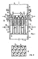
- Fig. 1 is a sectional view of a portion of a heat exchanger made in accordance with the invention; and
- Fig. 2 is a partial sectional view taken on line II-II of Fig. 1.
- Referring now to Fig. 1, there is shown a
heat exchanger 20 made in accordance with the invention. Theheat exchanger 20 comprises a shell 22, an abrasive fluid (not shown)inlet 24 penetrating the top of the shell 22, aninlet plenum 26 disposed within and at the top of the shell 22, anupper tubesheet 28 disposed within the shell 22 adjacent to theinlet plenum 26,tubes 30 extending through theupper tubesheet 28 and in fluid communication with theinlet plenum 26 and a tubeinlet guide configuration 32 disposed between theupper tubesheet 28 and the inlet plenum. The tubeinlet guide configuration 32 comprises a series of funnel shapedtubular extensions 34 with lower ends 36 andupper ends 38 and may be of any erosion resistant material, such as metal or refractory ceramic or steel coated with erosion resistant facing. The lower ends 36 are disposed within thetubes 30 and extend downwardly below theupper tubesheet 28, and theupper ends 38 are flared outwardly against theupper ends 38 of adjacenttubular extensions 34, and preferably welded, brazed or otherwise sealingly attached to form a gas-tight barrier. The invention further comprises a cooling means for the guide configuration, which in the preferred embodiment includes a cooling system 40 comprising a coolingfluid inlet penetration 42 in the side of the shell 22, acooling fluid passageway 44 disposed between the tubeinlet guide configuration 32 and theupper tubesheet 28 and in flow communication with the coolingfluid inlet penetration 42, and a coolingfluid outlet penetration 46 in fluid communication with thecooling fluid passageway 44. Disposed within thecooling fluid passageway 44 may be a baffle 48. - Looking now at Fig. 2, there is shown a partial sectional view of the tube
inlet guide configuration 32 looking downwardly. As can be seen, there is a minimum of surface area which is perpendicular to the axis of thetubes 30. - Referring again to Fig. 1, the
tubes 30 pass through aheat exchanger plenum 50 adjacent to and below theupper tubesheet 28, thence through alowertubesheet 52 which is adjacent to and below theheat exchange plenum 50. Anoutlet plenum 54 is adjacent to and below thelower tubesheet 52. Theinlet plenum 26 is in flow communication with theoutlet plenum 54 by way of thetubes 30. Anabrasive fluid outlet 56 penetrates the bottom of the shell 22. A heat removal fluidinfluent nozzle 58 and a heat removal fluid effluent nozzle 60 penetrate the shell 22 between theupper tubesheet 28 and thelower tubesheet 52. - In the preferred form, the tube
inlet guide configuration 32 is attached to a removable shell section orspool piece 62. The attachment may be by a weld means at ajoint 64. Theremovable shell section 62 is secured to the shell 22 atflanges 66, which may be held together by weld means or bolt means. - The heat exchanger operates in the following manner. Referring to Fig. 1, an abrasive fluid, such as raw gas from a carbonaceous material gasifier, enters the
heat exchanger 20 through theabrasive fluid inlet 24 into theinlet plenum 26 and towards the tubeinlet guide configuration 32. The flare of the tubular extensionupper ends 38 act to guide the raw gas into thetubes 30 and past theupper tubesheet 28. A cooling fluid, which may be raw gas which has been cooled and cleansed of particulate material, enters the coolingfluid inlet penetration 42, passes through thecooling fluid passageway 44 and exits through the coolingfluid outlet penetration 46. During the time the cooling fluid is within thecooling fluid passageway 44, part of the cooling fluid cools the tubular extensionupper ends 38 and part of the cooling fluid cools theupper tubesheet 28. An additional amount of cooling fluid may escape between the tubular extension lower ends 36 and thetubes 30, which may not be a leak-tight seal. - The angle 8 of the flare of the tubular extension
upper ends 38 away from the vertical axis of thetubes 30 may be between 20° and 40°. The optimum angle 8 is one which will provide the smallest amount of surface area which is perpendicular to the raw gas flow while at the same time providing for a change in direction of the raw gas into thetubes 30 which is as small a rate of change of direction as possible. - In the preferred embodiment, the entire tube
inlet guide configuration 32 will be attached to aremovable shell section 62 of the shell 22 which can be easily removed. In this preferred form, thetubular extensions 34 will not be attached to thetubes 30 but only fit snugly enough to allow leakage of the cooling fluid into thetubes 30. This results in additional cooling of theupper tubesheet 28.
Claims (6)
Applications Claiming Priority (2)
| Application Number | Priority Date | Filing Date | Title |
|---|---|---|---|
| US06/432,034 US4585057A (en) | 1982-09-30 | 1982-09-30 | Cooled tubesheet inlet for abrasive fluid heat exchanger |
| US432034 | 1982-09-30 |
Publications (2)
| Publication Number | Publication Date |
|---|---|
| EP0105442A1 EP0105442A1 (en) | 1984-04-18 |
| EP0105442B1 true EP0105442B1 (en) | 1986-09-10 |
Family
ID=23714488
Family Applications (1)
| Application Number | Title | Priority Date | Filing Date |
|---|---|---|---|
| EP83109576A Expired EP0105442B1 (en) | 1982-09-30 | 1983-09-26 | Cooled tubesheet inlet for abrasive fluid heat exchanger |
Country Status (11)
| Country | Link |
|---|---|
| US (1) | US4585057A (en) |
| EP (1) | EP0105442B1 (en) |
| JP (1) | JPS5977299A (en) |
| KR (1) | KR840006066A (en) |
| AU (1) | AU553913B2 (en) |
| BR (1) | BR8305159A (en) |
| CA (1) | CA1206951A (en) |
| DE (1) | DE3366108D1 (en) |
| ES (1) | ES8500432A1 (en) |
| IN (1) | IN158197B (en) |
| ZA (1) | ZA836717B (en) |
Families Citing this family (29)
| Publication number | Priority date | Publication date | Assignee | Title |
|---|---|---|---|---|
| DE3533219C1 (en) * | 1985-09-18 | 1986-11-13 | Borsig Gmbh, 1000 Berlin | Tube bundle heat exchanger |
| US4785877A (en) * | 1986-05-16 | 1988-11-22 | Santa Fe Braun Inc. | Flow streamlining device for transfer line heat exchanges |
| DE3715712C1 (en) * | 1987-05-12 | 1988-07-21 | Borsig Gmbh | Heat exchanger especially for cooling cracked gas |
| US5258165A (en) * | 1991-06-26 | 1993-11-02 | Osmonics, Inc. | Multi-tube ozone generator and method of making same |
| DE59200074D1 (en) * | 1992-04-29 | 1994-03-31 | Borsig Babcock Ag | Heat exchanger for cooling synthesis gas generated in a coal gasification plant. |
| US5362454A (en) * | 1993-06-28 | 1994-11-08 | The M. W. Kellogg Company | High temperature heat exchanger |
| DE4404068C1 (en) * | 1994-02-09 | 1995-08-17 | Wolfgang Engelhardt | Heat exchanger |
| DE19501422C2 (en) * | 1995-01-19 | 2002-03-28 | Borsig Gmbh | Cooled transition piece between a heat exchanger and a reactor |
| US5630470A (en) * | 1995-04-14 | 1997-05-20 | Sonic Environmental Systems, Inc. | Ceramic heat exchanger system |
| CA2191379A1 (en) | 1995-11-28 | 1997-05-29 | Cuddalore Padmanaban Natarajan | Heat exchanger for use in high temperature applications |
| US5647432A (en) * | 1996-04-10 | 1997-07-15 | Blasch Precision Ceramics, Inc. | Ceramic ferrule and ceramic ferrule refractory wall for shielding tube sheet/boiler tube assembly of heat exchanger |
| DE19847770A1 (en) * | 1998-10-16 | 2000-04-20 | Borsig Gmbh | Heat exchanger with a connector |
| DE20307881U1 (en) * | 2003-05-21 | 2004-09-23 | Autokühler GmbH & Co. KG | Heat exchanger/charge cooler for a motor vehicle, has pipes to form a heat exchanger network, a collector with a receiver and flow-conducting elements with tapered thicknesses |
| JP2007247950A (en) * | 2006-03-15 | 2007-09-27 | Tokyo Roki Co Ltd | Tube heat exchanger |
| GB0705439D0 (en) * | 2007-03-22 | 2007-05-02 | Alstom Intellectual Property | Improved flue gas cooling and cleaning arrangment |
| US20080302520A1 (en) * | 2007-06-06 | 2008-12-11 | Alcoa Inc. | Heat Exchanger |
| CN100453948C (en) * | 2007-07-20 | 2009-01-21 | 中国石化扬子石油化工有限公司 | A vertical shell-and-tube heat exchanger and its anti-blocking method |
| EP2407228B1 (en) * | 2010-07-14 | 2016-09-07 | General Electric Technology GmbH | Gas cleaning unit and method for cleaning gas |
| EP2431498B1 (en) * | 2010-09-17 | 2016-12-28 | General Electric Technology GmbH | Pot heat exchanger |
| EP2431499B1 (en) * | 2010-09-17 | 2014-04-23 | Alstom Technology Ltd | Raw gas collection system |
| CN102564205B (en) * | 2012-01-16 | 2014-06-11 | 杭州沈氏换热器有限公司 | Flow distributing structure of heat exchanger with micro-channels |
| DE102013100887A1 (en) * | 2013-01-29 | 2014-07-31 | Benteler Automobiltechnik Gmbh | Guide plate in the heat exchanger |
| US20160215735A1 (en) * | 2013-09-11 | 2016-07-28 | International Engine Intellectual Property Company, Llc | Thermal screen for an egr cooler |
| DE102016103229B4 (en) * | 2016-02-24 | 2020-06-25 | Arianegroup Gmbh | Injection into tubes of a shell and tube heat exchanger |
| US10126021B2 (en) * | 2016-07-15 | 2018-11-13 | General Electric Technology Gmbh | Metal-ceramic coating for heat exchanger tubes of a central solar receiver and methods of preparing the same |
| SI3376150T1 (en) | 2017-03-14 | 2019-11-29 | Alfa Laval Olmi S P A | Protection device for a shell-and-tube equipment |
| EP3499171A1 (en) | 2017-12-15 | 2019-06-19 | ALFA LAVAL OLMI S.p.A. | Anti-erosion device for a shell-and-tube equipment |
| KR101976745B1 (en) * | 2018-11-09 | 2019-05-09 | ㈜ 엘에이티 | High Efficiency Waste Heat Recovery Device of Hot Air Oven |
| DE102019120096A1 (en) | 2019-07-25 | 2021-01-28 | Kelvion Machine Cooling Systems Gmbh | Shell and tube heat exchanger |
Citations (1)
| Publication number | Priority date | Publication date | Assignee | Title |
|---|---|---|---|---|
| US4346758A (en) | 1979-04-03 | 1982-08-31 | Borsig Gmbh | Heat exchanger for cooling slag-containing gases from coal gasification |
Family Cites Families (18)
| Publication number | Priority date | Publication date | Assignee | Title |
|---|---|---|---|---|
| DE258892C (en) * | ||||
| US1348455A (en) * | 1918-05-21 | 1920-08-03 | Spicer George | Vaporizer for internal-combustion engines |
| US1995768A (en) * | 1934-03-23 | 1935-03-26 | Hugo P Fesenmaier | Tubular heat exchange structure and a surrounding shell therefor |
| US2986454A (en) * | 1957-07-23 | 1961-05-30 | American Cyanamid Co | Tubular catalytic converter |
| US3374832A (en) * | 1966-05-13 | 1968-03-26 | Lummus Co | Inlet cone device and method |
| US3416598A (en) * | 1966-08-26 | 1968-12-17 | Lummus Co | Inlet device and method for preventing coke build-up |
| GB1212526A (en) * | 1967-06-15 | 1970-11-18 | Foster Wheeler Brown Boilers | Improvements in shell and tube heat exchangers |
| US3409407A (en) * | 1967-07-31 | 1968-11-05 | Diamond Shamrock Corp | Corrosion resistant flame reactor |
| NL6919308A (en) * | 1968-12-27 | 1970-06-30 | ||
| GB1291847A (en) * | 1969-12-22 | 1972-10-04 | Basf Ag | A hot-gas cooler |
| US3702633A (en) * | 1971-08-23 | 1972-11-14 | Raygo Inc | Gas-to-gas heat exchanger |
| IN145015B (en) * | 1974-04-25 | 1978-08-12 | Shell Int Research | |
| US4173615A (en) * | 1974-07-08 | 1979-11-06 | Mitsui Toatsu Chemicals, Incorporated | Chemical apparatus for corrosive materials |
| US4103738A (en) * | 1976-08-16 | 1978-08-01 | Smith Engineering Company | Replaceable inlet means for heat exchanger |
| US4097544A (en) * | 1977-04-25 | 1978-06-27 | Standard Oil Company | System for steam-cracking hydrocarbons and transfer-line exchanger therefor |
| JPS5549693A (en) * | 1978-10-04 | 1980-04-10 | Mitsubishi Heavy Ind Ltd | Multitubular heat exchanger |
| JPS5563395A (en) * | 1978-11-01 | 1980-05-13 | Toyo Eng Corp | Heat exchanger |
| JPS5716793A (en) * | 1980-07-03 | 1982-01-28 | Takasago Thermal Eng Co Lts | Heat exchanger for collecting heat of exhaust gas |
-
1982
- 1982-09-30 US US06/432,034 patent/US4585057A/en not_active Expired - Fee Related
-
1983
- 1983-08-23 AU AU18324/83A patent/AU553913B2/en not_active Ceased
- 1983-08-25 IN IN1040/CAL/83A patent/IN158197B/en unknown
- 1983-09-09 ZA ZA836717A patent/ZA836717B/en unknown
- 1983-09-09 CA CA000436387A patent/CA1206951A/en not_active Expired
- 1983-09-21 BR BR8305159A patent/BR8305159A/en unknown
- 1983-09-22 JP JP58176196A patent/JPS5977299A/en active Pending
- 1983-09-26 EP EP83109576A patent/EP0105442B1/en not_active Expired
- 1983-09-26 DE DE8383109576T patent/DE3366108D1/en not_active Expired
- 1983-09-28 ES ES526023A patent/ES8500432A1/en not_active Expired
- 1983-09-28 KR KR1019830004562A patent/KR840006066A/en not_active Withdrawn
Patent Citations (1)
| Publication number | Priority date | Publication date | Assignee | Title |
|---|---|---|---|---|
| US4346758A (en) | 1979-04-03 | 1982-08-31 | Borsig Gmbh | Heat exchanger for cooling slag-containing gases from coal gasification |
Also Published As
| Publication number | Publication date |
|---|---|
| BR8305159A (en) | 1984-05-02 |
| ZA836717B (en) | 1984-05-30 |
| KR840006066A (en) | 1984-11-21 |
| ES526023A0 (en) | 1984-10-01 |
| US4585057A (en) | 1986-04-29 |
| CA1206951A (en) | 1986-07-02 |
| AU553913B2 (en) | 1986-07-31 |
| ES8500432A1 (en) | 1984-10-01 |
| EP0105442A1 (en) | 1984-04-18 |
| IN158197B (en) | 1986-09-27 |
| JPS5977299A (en) | 1984-05-02 |
| AU1832483A (en) | 1984-04-05 |
| DE3366108D1 (en) | 1986-10-16 |
Similar Documents
| Publication | Publication Date | Title |
|---|---|---|
| EP0105442A1 (en) | Cooled tubesheet inlet for abrasive fluid heat exchanger | |
| US4372253A (en) | Radiation boiler | |
| GB1558953A (en) | Gasification of solid fuel via partial oxidation | |
| PL191585B1 (en) | Processes and apparatus for reacting gaseous reactants containing solid particles | |
| EP1814966B1 (en) | Apparatus for gasifying a fuel | |
| AU2002368080A1 (en) | Method for gasification of a solid carbonaceous feed and a reactor for use in such a method | |
| EP0094098A1 (en) | High temperature cyclone separator for gasification system | |
| AU665959B2 (en) | A method of removing deposits from the walls of a gas cooler inlet duct, and a gas cooler inlet duct having a cooled elastic metal structure | |
| US3712371A (en) | Method for heat recovery from synthesis gas | |
| EP0160424B1 (en) | Quench ring and dip tube assembly | |
| CA2167564C (en) | Apparatus for cooling solids laden hot gases | |
| KR20160071334A (en) | Quench-cooling system | |
| EP0774103B1 (en) | Apparatus for cooling hot gas | |
| US3318374A (en) | Protectors for heating surfaces of boiler tubes | |
| CA1265784A (en) | Method and apparatus for recovering heat from gases containing substances which contaminate heat transfer surfaces | |
| US5458859A (en) | Device for removing heavy metals and slags from synthesis gas produced from refinery wastes | |
| JPH0797579A (en) | Coal gasifier | |
| EP0094097A2 (en) | Non-plugging, pressure equalized tube sheet for gasification system heat exchanger | |
| EP0536135B1 (en) | Gas cooler for heat transfer by convection | |
| EP0074461A1 (en) | Cold wall separator | |
| US4286970A (en) | Reactor with particulate recycling filtration means | |
| EP0095011A2 (en) | Carryover barrier for gasification system | |
| JPH0615949B2 (en) | Raw gas / pure gas heat exchanger | |
| US4421063A (en) | Fluidized bed combustion apparatus | |
| SU1079347A1 (en) | Apparatus for metal casting |
Legal Events
| Date | Code | Title | Description |
|---|---|---|---|
| PUAI | Public reference made under article 153(3) epc to a published international application that has entered the european phase |
Free format text: ORIGINAL CODE: 0009012 |
|
| AK | Designated contracting states |
Designated state(s): BE DE FR GB IT |
|
| 17P | Request for examination filed |
Effective date: 19841018 |
|
| RAP1 | Party data changed (applicant data changed or rights of an application transferred) |
Owner name: KRW ENERGY SYSTEMS INC. |
|
| ITF | It: translation for a ep patent filed | ||
| GRAA | (expected) grant |
Free format text: ORIGINAL CODE: 0009210 |
|
| AK | Designated contracting states |
Kind code of ref document: B1 Designated state(s): BE DE FR GB IT |
|
| ET | Fr: translation filed | ||
| REF | Corresponds to: |
Ref document number: 3366108 Country of ref document: DE Date of ref document: 19861016 |
|
| PLBI | Opposition filed |
Free format text: ORIGINAL CODE: 0009260 |
|
| 26 | Opposition filed |
Opponent name: DEUTSCHE BABCOCK AKTIENGESELLSCHAFT Effective date: 19870526 |
|
| BERE | Be: lapsed |
Owner name: KRW ENERGY SYSTEMS INC. Effective date: 19870930 |
|
| PG25 | Lapsed in a contracting state [announced via postgrant information from national office to epo] |
Ref country code: GB Effective date: 19880926 |
|
| RDAG | Patent revoked |
Free format text: ORIGINAL CODE: 0009271 |
|
| STAA | Information on the status of an ep patent application or granted ep patent |
Free format text: STATUS: PATENT REVOKED |
|
| GBPR | Gb: patent revoked under art. 102 of the ep convention designating the uk as contracting state | ||
| 27W | Patent revoked |
Effective date: 19881208 |
|
| GBPC | Gb: european patent ceased through non-payment of renewal fee |