EP0105406B1 - Baueinheiten - Google Patents
Baueinheiten Download PDFInfo
- Publication number
- EP0105406B1 EP0105406B1 EP19830109356 EP83109356A EP0105406B1 EP 0105406 B1 EP0105406 B1 EP 0105406B1 EP 19830109356 EP19830109356 EP 19830109356 EP 83109356 A EP83109356 A EP 83109356A EP 0105406 B1 EP0105406 B1 EP 0105406B1
- Authority
- EP
- European Patent Office
- Prior art keywords
- floor
- roof
- beams
- unit
- leg
- Prior art date
- Legal status (The legal status is an assumption and is not a legal conclusion. Google has not performed a legal analysis and makes no representation as to the accuracy of the status listed.)
- Expired
Links
Images


Classifications
-
- E—FIXED CONSTRUCTIONS
- E04—BUILDING
- E04B—GENERAL BUILDING CONSTRUCTIONS; WALLS, e.g. PARTITIONS; ROOFS; FLOORS; CEILINGS; INSULATION OR OTHER PROTECTION OF BUILDINGS
- E04B1/00—Constructions in general; Structures which are not restricted either to walls, e.g. partitions, or floors or ceilings or roofs
- E04B1/348—Structures composed of units comprising at least considerable parts of two sides of a room, e.g. box-like or cell-like units closed or in skeleton form
- E04B1/34815—Elements not integrated in a skeleton
- E04B1/3483—Elements not integrated in a skeleton the supporting structure consisting of metal
Definitions
- This invention relates to a portable building unit for a building construction formed from one or more such portable building units, hereinafter referred to as "of the kind specified", the or each of which is a factory assembled, self-contained portable unit for delivery to a site of an assembled condition complete with floor structure, walls and roof structure, and preferably complete with all windows, doors and internal fittings.
- portable building units for a building construction formed from one or more such portable building units, hereinafter referred to as "of the kind specified”, the or each of which is a factory assembled, self-contained portable unit for delivery to a site of an assembled condition complete with floor structure, walls and roof structure, and preferably complete with all windows, doors and internal fittings.
- provision for coupling the units together in the desired arrangement is built into the units before they leave the factory, so that the only on-site assembly work required is that of coupling the units together.
- Such a building is described in our previous Patent GB-A-1315132.
- GB-A-1315132 discloses a building unit of the kind specified which has been used widely in many applications such as site offices on building or other construction sites, at outdoor exhibitions and sports events, and as temporary or semi-permanent office, laboratory or living accommodation. Buildings made from such units have been regarded as being essentially temporary or at most semi-permanent and the appearance of the buildings has been in line with this.
- the present invention is based on a new philosophy of providing essentially permanent accommodation, not by traditional methods of construction in which a building is erected on site from components such as bricks and mortar, or steel framework and cladding, but by means of factory assembled portable building units which can thus be transported to the building site and be positioned there as permanent buildings.
- a building constructed according to this new philosophy is described in our previous Patent GB-A-2084213. However, this building is actually intended for essentially permanent accommodation and must be positioned on a prepared foundation which engages and supports a floor subframe of the building unit.
- the invention seeks to adopt this new philosophy to temporary buildings.
- the present invention provides a self-contained portable building unit of the kind which is factory assembled for delivery to a site in an assembled condition comprising a floor structure, stressed skin structural sandwich side and end wall panels to provide walls, a floor structure, side and end wall panels to provide walls, a roof structure, and windows, doors and internal fittings and further comprising two longitudinal extending skids disposed beneath the floor structure, four legs disposed symmetrically, two on each side of the unit intermediate the ends thereof and externally of the wall panels, a transverse compression member extending between and being connected to the upper ends of the legs of each oppositely disposed pair of legs and each leg having a ground-engagable foot member whereby the unit is supportable on the foot members with the roof and floor loads being transmitted by the wall panels to the legs characterised in that the floor structure comprises two spaced, parallel, floor side beams disposed at the sides of the floor structure and extending longitudinally of the unit, a plurality of cross beams, extending transversely of the unit and connected between the floor side beams
- the building unit may be provided with a floor level above the ground which is considerably reduced compared with the floor level obtained with such a prior building, e.g. as little as 32.5 cm above the ground, thereby avoiding any considerable step-up into the building, and secondly, the underside of the floor structure is concealed at least from side view thus giving the unit of the present invention a much more permanent visual appearance and impression in use.
- a unit in accordance with the invention has structural integrity afforded by a frame which includes the roof and floor side beams, the legs and importantly the transverse compression member.
- Each leg may be disposed so as to intersect the associated roof side beam so that the leg and associated roof side beam are substantially co-planar and the side wall panel is disposed inwardly of the leg and associated roof side beam and externally of the floor side beam.
- the roof structure may comprise an upper skin and a lower skin, a plurality of cross beams spanning between the roof beams and disposed between the upper and the lower skins, and said compression member also being disposed between the upper and lower skins.
- the cross beams may be underdrawn by lower cladding panels and the skids may also be secured to the cross beams to depend from the underside thereof, the lower cladding panels extending between the skids.
- thermally insulating material may be disposed in the region between the floor deck and the lower panels and/or the upper and lower skins of the roof structure.
- the floor side beams may be made of metal such as steel and may be 305 mm deep.
- the cross beams may be made of metal such as steel.
- the side and end walls may each comprise a structural sandwich having inner and outer skins sandwiching therebetween, and being bonded to, a rigid foam or expanded plastics material.
- the outer skin may be a plastics coated steel sheet and the inner skin plasterboard, with a peripheral timber frame disposed between the inner and outer skins.
- the floor deck may comprise a flooring guide wood particle board panel.
- the upper skin may comprise one or more sheets of wood particle board supported by timber joists.
- the inner skin may comprise a gypsum wallboard panel faced with plastic film.
- Each leg may have a slinging point, which may be removable, at or adjacent its upper end whereby the building may be lifted with a crane.
- each slinging point comprises an adaptor retractable into the upper end of the associated leg, when not in use.
- the upper unit may be secured to the lower unit using the slinging point of the lower unit, for example by bolting.
- the ground-engageable foot member may be spaced closely below the lowest part of the side beams, or alternatively, the ground-engageable foot members may be engageable with the legs in a plurality of relative operative positions which permit the building unit to be supported on the foot members at a range of positions above the ground, varying from relatively close to the ground to sufficiently above the ground for a transporter, such as a lorry, to be driven under the building unit and the legs retracted the building unit is supported on the transporter by means of the skids.
- a transporter such as a lorry
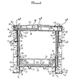
- FIG. 1 and 2 there is shown a portable building of generally right para- lellopiped configuration having two side walls 12 and two end walls 13, a roof structure 14 and a floor structure 15.
- Door and window openings are provided in the walls as shown at 16 and 17 respectively.
- the doors and windows may be located at other positions than those shown and if desired more or less doors and windows may be provided.
- the building unit is also provided with four legs 18, two on each side of the unit, arranged symmetrically.
- Figure 3 merely shows a building unit similar to that of Figures 1 and 2 but of different dimensions, and having an alternative arrangement of doors and windows.
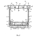
- the floor structure 15 comprises two parallel longitudinally extending floor side beams 19, 20 disposed to extend along the longitudinal sides of the floor structure.
- the floor side beams 19, 20 are identical and are made as rolled sections in steel and are of essentially channel configuration having inturned lips 21 of the free ends of the limbs 22 of the channel.
- the side beams 19, 20 Fastened by welding, to the side beams 19, 20 are a plurality of cross beams 23 which extend transversely of the floor structure and are located at spaced positions longitudinally of the side beams 19, 20.
- the cross beams 23 are provided with cut-outs 28 at each end to accommodate the limbs 22 and associated lips 21 of the side beams 19, 20.
- the cross beams are 400 mm apart, the cross beams and floor side beams are made from galvanised steel; the side beams 19, 20 are 305 mm deepx89 mm flange with 19 mm lipx3.175 mm sheet steel, giving a minimum yield stress of 220 N/mm 2 .
- the cross beams are 180 mm deepx55 mm flange with 12 mm Iipx2.50 mm sheet steel.
- a floor deck 24 made of flooring grade wood particle board with a fully bonded vinyl covering. However, if desired, other material may be used.
- the nature of the floor deck which is 18 mm thick and moisture resistant, provides the floor structure with a very solid feel and this is aided by the floor covering of 1.25 mm thick vinyl.
- the cross beams are underdrawn with a lower cladding panel assembly comprising a plurality of bitumen impregnated fibreboard panels 25 secured to the underside of the cross beams 23.
- a mineral fibre insulation mat 26 is packed between the side beams and cross beams.
- the cross beams 23 are connected down their length on the underside thereof, by two U-shaped skids 27 also made of galvanised rolled steel section and which are provided to sit on a lorry bed during transportation.
- the floor can be strengthened to take high loadings and if necessary supported directly on the ground along its entire length.
- Each wall of the building unit is formed as a panel having stressed skin structural sandwich of inner and outer skins 30, 31 which sandwich therebetween and are bonded together by means of rigid polyurethane foam 32.
- a peripheral timber frame 33 is provided between the inner and outer skins.
- the outer skin 31 comprises a coloured steel cladding, for example, galvanised sheet steel having a coloured PVC coating on the external surface to give a longer maintenance free life.
- the panels are seamed vertically such as described in one published Application GB-A-1520272 to give a continuous external weather barrier with no potential weaknesses for leaks.
- the steel is galvanised prior to the application of the PVC exterior to give added protection in the event of damage to the PVC coating.
- the internal skin 30 is made of gypsum wallboard with a textured vinyl wall covering giving a smart, easy-clean internal finish.
- the polyurethane foam 32 is 47 mm thick which gives good thermal insulation and securely bonds the skins together into an effective thermal barrier guaranteeing good control over the internal environment.
- the gypsum wallboard inner skin gives a half hour fire resistance from the inside as standard and internal and external surfaces are designated Class "0". In addition the wall panels have good sound attenuation.
- the wall panels are secured to the floor structure by suitable fasteners such as nails pnuemati- cally driven through the lower member of the peripheral timber frame 33 and into a web part 34 of the floor side beams 19, 20 or a web part 35 of appropriately disposed end cross beams 23 depending upon whether the panels are side or end wall panels.
- suitable fasteners such as nails pnuemati- cally driven through the lower member of the peripheral timber frame 33 and into a web part 34 of the floor side beams 19, 20 or a web part 35 of appropriately disposed end cross beams 23 depending upon whether the panels are side or end wall panels.
- angle members 36 are provided on the floor side beams and end cross beams to support the walls.
- the side wall panels are connected, by suitable fasteners (not shown) such as wood screws, to longitudinally extending roof side beams 37 of assymetric Z-configuration, the wall panels engaging a part 38 of a web of the beams 37 which extends perpendicular to one flange 39, thereof and which is connected to its other end by an inclined part 41 and a cranked part 42a, to a flange 40.
- the flanges 39, 40 at their free ends have upturned lips, the flange 39 having an out-turned lip 43 and the flange 40 having a smaller inturned lip 44.
- the roof side beams 37 comprise two end parts 37a, 37b (see Figures 1 and 3) and an intermediate part 37c.
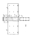
- the intermediate part 37c is bolted at either end to a channel section part 41b of a fabricated assembly 41a at the top of the legs 18.
- One of the assemblies 41a is shown in more detail in Figures 6 and 7.
- One end of each of the end parts 37a, 37b are also bolted to an assembly 41a.
- the side beams 37 are effectively continuous along the length of the building by virtue of the channel 41b of the assembly 41a.
- the roof side beams 37 comprise painted galvanised rolled steel sections and the above described section provides an aesthetically pleasing facia appearance on the exterior of the building.
- the roof side beams 37 are made of 3.000 mm thick galvanised sheet sheel having a minimum yield stress of 220 N/mm 2 .
- the assembly 41a comprises a socket part 41c in which a spigot 41d is welded, the spigot being received in the upper end of the associated leg 18.
- the spigots 41d are bolted inside the upper leg parts by bolts 18' and at their lower ends the legs 18 have a flanged lug 46 connected by bolts 47 to the floor side beams 19, 20.
- the legs including spigot 41d and socket part 41c extend beyond the top of the side beams 37 where they are bolted via plates 42 to a compression member 48 which extends between the upper ends of the thus extended legs 18.
- Each leg 18 is over the entire length (including socket 41b) of square tubular configuration and terminates at the lower end in a foot member comprising a foot plate 52 adapted to engage the ground or lower unit in a double stack configuration.
- the legs 18 terminate at a position P 1 at the top surface of the foot plate 52, below the floor side beams 19, 20 which are at a level P 2 .
- foot member having a long shank and which is connectable to the leg 18 in a plurality of positions so that the building may be supported at a desired height above the ground, for example, to permit a transporter such as a lorry to be driven beneath the building unit so that the building unit can be supported on the back of the lorry via the skids 27, in such case the legs 18 and foot members 50 may be as described in U.K. Specification GB-A-1315132.
- Lifting adaptors 51 provide slinging points for the building unit of the upper ends of the legs 18 within socket port 41c, details of which can best be seen from Figures 6 and 7.
- the adaptors 51 can be retracted into the sockets 41 c at the upper ends of the legs when not in use, and withdrawn therefrom when required.
- an abutment 51b is provided within the socket 41c at the upper end of the leg 18, which, in use, would engage an abutment 51c at the lower end of the adaptor 51.
- a first opening 51d is provided in adaptor 51 through which a shackle of a crane or the like may be passed when the adaptor 51 is extended, and an opening 51e is provided within the socket 41c through which a pin or bolt can be passed when the adaptor 51 is in an extended position, to prevent retraction.
- the adaptors 51 can rotate about their longitudinal axes 51' to align the openings 51d during lifting.
- the upper unit may be secured to the lower unit by the adaptors 51, as hereinafter explained.
- a two-part skirting board made as an extrusion in synthetic plastics material is provided at the bottom of the internal surface of each wall and can provide a conduit for services, access to which can be gained by removing a cover part 53 from a backing part 54 thereof.
- a somewhat similar two-part trim arrangement is provided at the top of the walls as indicated at 55.
- the roof comprises a plurality of wooden joists 56 with end ruanners 56a and a centre wooden noggin 56b.
- the roof joists 56 are contoured as desired to give a desired profile to the roof, in this case a light camber.
- the joists 56 are at 603 mm centres supported at their ends on the upper limb 39 of the roof side beams 37 and supporting a wood particle board upper skin 57, 18 mm thick with a one-piece hypalon steel 58 fully bonded to the roof deck with a neoprene latex adhesive and the edges of the sheet are bonded to the roof edges with a contact adhesive.
- a mineral fibre thermal insulation mat 59 is packed between the joints 56 and rests on a vinyl covered plasterboard inner skin or ceiling 60 which is secured to the underside of the joints 56. If this example the insulation 59 is 60 mm thickx400 mm wide glass fibre mat.
- the plasterboard ceiling 60 is 12.7 mm thick and is suspended from the joists 56 by galvanised steel sections 56c which are themselves secured to the wooden joists 56.
- the steel sections are covered with white aluminium trim.
- a gutter in the form of a rigid PVC extrusion 61 is provided on the sides of the building and is fully supported along its length by a galvanised steel retention section 62 folded from essentially C-section steel sheet and fixed to the runners 56a by means of wood screws. Roof void ventilation is provided as indicated at 63 behind the gutters. A fall pipe is provided at each corner of the unit.
- the unit described above has structural integrity which is afforded by the steel frame which includes the roof side beams 37, floor side beams 19, 20, legs 18, fabricated assembly 41a, transverse compression members 48 and floor cross beams 23. It is to be noted that the steel compression members 48 span between the legs 18 within the roof assembly, i.e. beneath the roof deck 57 and above the lower cladding panel 60 and serve to prevent the roof being damaged during craning operations.
- the transverse structural steel members of the framework namely the floor cross beams 23 and compression members 48
- the building unit is given a more permanent visual impression than was the case with the building unit described in Specification GB-A-1315132 where the compression members lie externally of the roof and also compared with the building described in Specification GB-A-1493801 wherein the legs are connected together trans- versly by means of beams disposed at a level below the underside of the floor structure.
- the steel framework permits the unit to sit close to the ground without the need for damp-proofing and the relatively deep side members 19, 20, together with end panels 64, reduce air movement beneath the units therefore giving improved floor insulation.
- the end panels 64 are preferably pivotally mounted so as to pivot when the unit is to be transported on a lorry so as to enable the skids 27 to engage the deck of the lorry without interference by the end panel 64 as a result of the end panel 64 pivoting upwardly.
- the doors and windows 16,17 may be of any desired construction, it is preferred that the door 16 comprise a panel of essentially similar construction to the side panels, namely inner and outer skins of the materials described hereinbefore with rigid polyurethane foam sandwiched therebetween.
- the windows preferably have a top hung opening action and the window glass may be unpro- vided with any peripheral frame having hinges secured directly to the glass and the glass sealing onto a suitahble seal strip provided on the frame in the wall of the building unit.
- the windows would be made of a suitable toughened or laminated glass.
- the window frame which clamps to the wall is preferably of extruded aluminium and provided with a thermal break to reduce condensation on the frame and a channel is provided in the frame so that any condensation on the glass is channelled to the outside of the building unit.
- double glazing may be provided although in this case, the glass would need to be provided with a peripheral frame.
- the building unit described hereinbefore can be linked and double stacked to form larger complexes and if double stacked there will be no obvious gap between the upper and lower units due to the presence of the side beams 19, 20 and end panels 64.
- Stacking of the units may be achieved by providing in the foot members of the upper building unit, openings to receive the adaptors 51 of the lower unit, and openings may be provided in the lower part of the upper leg to receive a bolt or pin through the opening, which pin or bolt engages the opening 51 d of the associated adaptor 51.
- the building unit illustrated in Fiures 1 and 2 has an overall length of approximately 9.9 m and an internal width of 3.79 m, an overall width of 4.26 m, giving a floor area of 36.38 m 2 .
- the legs are at 7.2 mm centres.
- Building units in accordance with the invention may be of any different size, for example may be approximately 5.1 m long and 2.92 m internal width giving a floor area of 14.02 m 2 , or alternatively may be 18.3 m long with an internal width of 3.79 m giving a floor area of 68.22 m 2 and having a leg spacing of 9.6 m.
- Such a building unit is shown in Figure 3.
- the building units may, of course, be constructed in a range of sizes above, below and between those mentioned above.
Landscapes
- Engineering & Computer Science (AREA)
- Architecture (AREA)
- Physics & Mathematics (AREA)
- Electromagnetism (AREA)
- Civil Engineering (AREA)
- Structural Engineering (AREA)
- Floor Finish (AREA)
- Building Environments (AREA)
- Conveying And Assembling Of Building Elements In Situ (AREA)
Claims (10)
Applications Claiming Priority (2)
| Application Number | Priority Date | Filing Date | Title |
|---|---|---|---|
| GB8227511 | 1982-09-27 | ||
| GB8227511 | 1982-09-27 |
Publications (2)
| Publication Number | Publication Date |
|---|---|
| EP0105406A1 EP0105406A1 (de) | 1984-04-18 |
| EP0105406B1 true EP0105406B1 (de) | 1989-11-29 |
Family
ID=10533189
Family Applications (1)
| Application Number | Title | Priority Date | Filing Date |
|---|---|---|---|
| EP19830109356 Expired EP0105406B1 (de) | 1982-09-27 | 1983-09-20 | Baueinheiten |
Country Status (3)
| Country | Link |
|---|---|
| EP (1) | EP0105406B1 (de) |
| DE (2) | DE105406T1 (de) |
| GB (1) | GB2127879B (de) |
Cited By (2)
| Publication number | Priority date | Publication date | Assignee | Title |
|---|---|---|---|---|
| EP0263194A1 (de) * | 1986-10-07 | 1988-04-13 | Portakabin Limited | Transportable Baueinheit |
| FR2839329A1 (fr) | 2002-03-20 | 2003-11-07 | Portakabin Ltd | Structure de plancher |
Families Citing this family (4)
| Publication number | Priority date | Publication date | Assignee | Title |
|---|---|---|---|---|
| GB8727586D0 (en) * | 1987-11-25 | 1987-12-31 | Norcros Plc | Roof structures |
| GB9414682D0 (en) | 1994-07-21 | 1994-09-07 | Portakabin Ltd | Floor stucture |
| DE102010044036B4 (de) * | 2010-11-17 | 2012-11-29 | Erol Ludwig | Gebäude, welches oberhalb einer korrespondierend ausgeformten Bodenvertiefung angeordnet und in diese Bodenvertiefung absenkbar ist |
| CN107268922B (zh) * | 2017-06-22 | 2023-03-14 | 嘉兴天美环保集成墙面有限公司 | 一种组合墙板 |
Family Cites Families (12)
| Publication number | Priority date | Publication date | Assignee | Title |
|---|---|---|---|---|
| BE757271A (fr) * | 1969-10-10 | 1971-03-16 | Elcon Ag | Perfectionnements a la construction de batiments pre- fabriques |
| US3564786A (en) * | 1970-01-09 | 1971-02-23 | David Baker | Mass production housing |
| GB1315132A (en) * | 1970-11-18 | 1973-04-26 | Prtakabin Ltd | Portable building |
| CH535875A (de) * | 1971-04-13 | 1973-04-15 | Sovami Sa | Aus vorfabrizierten Teilen gebildete Baukonstruktion |
| US3832811A (en) * | 1971-06-07 | 1974-09-03 | E Briel | Relocatable building module |
| GB1459388A (en) * | 1972-09-11 | 1976-12-22 | Medway Building Ltd | Buildings |
| CH560296A5 (de) * | 1973-04-25 | 1975-03-27 | Credelca Ag | |
| FR2267435A1 (en) * | 1974-04-12 | 1975-11-07 | Lemettre Gerard | Modular steel-framed building construction - has welded crowns joining posts, floor base and foundation |
| RO79813A (ro) * | 1974-05-08 | 1982-09-09 | Industrielle De Constructions Mobiles,Fr | Constructie usoara prefabricata cu structura metalica |
| US3965557A (en) * | 1974-08-01 | 1976-06-29 | Pruitt Jr Robert L | Apparatus for affixing prealigned corner posts to box-like structures before assembling same |
| GB2084213B (en) * | 1980-09-19 | 1984-07-04 | Portakabin Ltd | Portable building unit |
| GB2092640B (en) * | 1981-02-07 | 1984-04-04 | Portakabin Ltd | Portable building unit |
-
1983
- 1983-09-15 GB GB08324725A patent/GB2127879B/en not_active Expired
- 1983-09-20 DE DE1983109356 patent/DE105406T1/de active Pending
- 1983-09-20 EP EP19830109356 patent/EP0105406B1/de not_active Expired
- 1983-09-20 DE DE8383109356T patent/DE3380899D1/de not_active Expired - Lifetime
Cited By (2)
| Publication number | Priority date | Publication date | Assignee | Title |
|---|---|---|---|---|
| EP0263194A1 (de) * | 1986-10-07 | 1988-04-13 | Portakabin Limited | Transportable Baueinheit |
| FR2839329A1 (fr) | 2002-03-20 | 2003-11-07 | Portakabin Ltd | Structure de plancher |
Also Published As
| Publication number | Publication date |
|---|---|
| EP0105406A1 (de) | 1984-04-18 |
| GB2127879A (en) | 1984-04-18 |
| GB2127879B (en) | 1985-10-02 |
| DE105406T1 (de) | 1989-09-14 |
| DE3380899D1 (de) | 1990-01-04 |
| GB8324725D0 (en) | 1983-10-19 |
Similar Documents
| Publication | Publication Date | Title |
|---|---|---|
| US5743056A (en) | Building panel and buildings made therefrom | |
| US11578482B2 (en) | Foldable enclosure members joined by hinged I-beam | |
| US4641468A (en) | Panel structure and building structure made therefrom | |
| US4813193A (en) | Modular building panel | |
| EP0635088B1 (de) | Bauelement und damit hergestellte gebaeude | |
| US4894964A (en) | Building structure and method | |
| CA2807504C (en) | Foldable building units | |
| WO2012012688A1 (en) | Building system and method | |
| US5323573A (en) | Building structure and method of erecting it | |
| US4310992A (en) | Structural panel | |
| GB2084213A (en) | Portable building unit | |
| EP0105406B1 (de) | Baueinheiten | |
| US4142335A (en) | Building construction | |
| EP0546540B1 (de) | Transportierbare Baueinheit | |
| US2078970A (en) | House construction | |
| EP0310926B1 (de) | Verfahren zur Errichtung eines Modulargebäudes | |
| WO1992019826A1 (en) | Beam or girder for building construction and a building unit including said beam or girder, and a method of manufacturing the beam or girder | |
| EP0270218A2 (de) | Dachbauweise in einem oder für einen Baumodul | |
| EP0263194B1 (de) | Transportable Baueinheit | |
| US20240183146A1 (en) | Load bearing system for a residential structure | |
| EP1132535B1 (de) | Transportable Baueinheit | |
| US4449334A (en) | Dormer structure and method | |
| RU2800657C2 (ru) | Модульное здание | |
| GB2246583A (en) | Roof structure with beam including service cavity | |
| Incoll | The Development Of Australian Antartic Building Types |
Legal Events
| Date | Code | Title | Description |
|---|---|---|---|
| PUAI | Public reference made under article 153(3) epc to a published international application that has entered the european phase |
Free format text: ORIGINAL CODE: 0009012 |
|
| AK | Designated contracting states |
Designated state(s): DE FR NL |
|
| 17P | Request for examination filed |
Effective date: 19840402 |
|
| DET | De: translation of patent claims | ||
| GRAA | (expected) grant |
Free format text: ORIGINAL CODE: 0009210 |
|
| AK | Designated contracting states |
Kind code of ref document: B1 Designated state(s): DE FR NL |
|
| REF | Corresponds to: |
Ref document number: 3380899 Country of ref document: DE Date of ref document: 19900104 |
|
| ET | Fr: translation filed | ||
| PLBE | No opposition filed within time limit |
Free format text: ORIGINAL CODE: 0009261 |
|
| PLBE | No opposition filed within time limit |
Free format text: ORIGINAL CODE: 0009261 |
|
| STAA | Information on the status of an ep patent application or granted ep patent |
Free format text: STATUS: NO OPPOSITION FILED WITHIN TIME LIMIT |
|
| 26N | No opposition filed | ||
| 26N | No opposition filed | ||
| PGFP | Annual fee paid to national office [announced via postgrant information from national office to epo] |
Ref country code: FR Payment date: 20010911 Year of fee payment: 19 |
|
| PGFP | Annual fee paid to national office [announced via postgrant information from national office to epo] |
Ref country code: NL Payment date: 20010927 Year of fee payment: 19 |
|
| PGFP | Annual fee paid to national office [announced via postgrant information from national office to epo] |
Ref country code: DE Payment date: 20011009 Year of fee payment: 19 |
|
| PG25 | Lapsed in a contracting state [announced via postgrant information from national office to epo] |
Ref country code: NL Free format text: LAPSE BECAUSE OF NON-PAYMENT OF DUE FEES Effective date: 20030401 Ref country code: DE Free format text: LAPSE BECAUSE OF NON-PAYMENT OF DUE FEES Effective date: 20030401 |
|
| PG25 | Lapsed in a contracting state [announced via postgrant information from national office to epo] |
Ref country code: FR Free format text: LAPSE BECAUSE OF NON-PAYMENT OF DUE FEES Effective date: 20030603 |
|
| REG | Reference to a national code |
Ref country code: FR Ref legal event code: ST |