EP0105380B1 - Bottom blowing gas nozzle in molten metal refining furnace and method of melting steel using the same nozzle - Google Patents
Bottom blowing gas nozzle in molten metal refining furnace and method of melting steel using the same nozzle Download PDFInfo
- Publication number
- EP0105380B1 EP0105380B1 EP83900974A EP83900974A EP0105380B1 EP 0105380 B1 EP0105380 B1 EP 0105380B1 EP 83900974 A EP83900974 A EP 83900974A EP 83900974 A EP83900974 A EP 83900974A EP 0105380 B1 EP0105380 B1 EP 0105380B1
- Authority
- EP
- European Patent Office
- Prior art keywords
- nozzle
- gas
- refractory
- holes
- blown
- Prior art date
- Legal status (The legal status is an assumption and is not a legal conclusion. Google has not performed a legal analysis and makes no representation as to the accuracy of the status listed.)
- Expired
Links
Images







Classifications
-
- C—CHEMISTRY; METALLURGY
- C21—METALLURGY OF IRON
- C21C—PROCESSING OF PIG-IRON, e.g. REFINING, MANUFACTURE OF WROUGHT-IRON OR STEEL; TREATMENT IN MOLTEN STATE OF FERROUS ALLOYS
- C21C5/00—Manufacture of carbon-steel, e.g. plain mild steel, medium carbon steel or cast steel or stainless steel
- C21C5/28—Manufacture of steel in the converter
- C21C5/42—Constructional features of converters
- C21C5/46—Details or accessories
- C21C5/48—Bottoms or tuyéres of converters
-
- B—PERFORMING OPERATIONS; TRANSPORTING
- B22—CASTING; POWDER METALLURGY
- B22D—CASTING OF METALS; CASTING OF OTHER SUBSTANCES BY THE SAME PROCESSES OR DEVICES
- B22D1/00—Treatment of fused masses in the ladle or the supply runners before casting
- B22D1/002—Treatment with gases
- B22D1/005—Injection assemblies therefor
Definitions
- a first embodiment of the present invention relates to a molten metal refining nozzle which is mounted for example in the bottom of a molten metal refining furnace for blowing gas therethrough and its object is to increase the flow control range of the refining nozzle during the gas blowing and also to increase the service life of the nozzle itself.
- a molten metal refining nozzle comprises a refractory having a plurality of holes extending from its working surface to its back, a metal cover enclosing the sides of the refractory, and a pressure box provided in the bottom of the refractory so as to communicate with the holes and define a gas reservoir space.
- JP-A-55-149750 and EP-A-0,021,861 illustrate examples of such a construction.
- the invention seeks to solve the foregoing unsolved problems of the molten metal refining nozzle for gas blowing purposes and it provides measures to overcome these problems.
- the invention provides a bottom-blown gas blowing nozzle for a molten metal refining furnace, comprising a refractory including a plurality of holes formed therethrough to extend from a working surface to a bottom surface thereof, a metal cover enclosing a part or whole of the sides of said refractory and a pressure box formed at the bottom portion of said refractory so as to communicate with said holes and define a gas reservoir, characterised in that the refractory includes a first group of a plurality of holes extending therethrough and a second group of a plurality of holes extending therethrough and surrounding said first group of holes, the diameter of each hole of said second group thereof being smaller than that of each hole of said first group thereof.
- the spacing between the plurality of holes in the refractory is preferably selected not less than 3 mm and not greater than 150 mm.
- Each of the plurality of holes in the refractory is preferably provided by a metal tube embedded in the refractory and the wall thickness of the metal tubes is selected not less than 0.1 mm and not greater than 10 mm.
- the metal cover preferably comprises a steel plate having a thickness of not less than 0.1 mm and not greater than 5 mm.
- the distance between the upper and lower metal plates defining the gas reservoir space of the pressure box is preferably selected not less than 2 mm and not greater than 50 mm.
- (1) is a refractory made of non-porous brick
- (2) is a nozzle hole
- (2') is a nozzle hole of a radially outer series thereof
- (2") is a nozzle hole of a radially inner series thereof
- (3) is a metal cover
- (4) is a pressure box
- (5) is an upper metal plate
- (6) is a lower metal plate
- (7) is a gas induction pipe
- (8) is an outer sleeve
- (9) is a set brick
- (10) is a shell
- (11) is a porous refractory
- (12) is a gas sealing coating material or shell
- (13) is a bottom shell
- (14) is a gas induction pipe
- (15) is a small tube
- (16) is a non-porous refractory nozzle
- (17) is a gas pressure equalizing chamber
- (18) is a gas sealing coating
- (19) is a converter bottom
- (20) represents a mounting position of
- FIG. 1 shows an example in which a molten metal refining nozzle is mounted in the bottom of a molten metal vessel
- Figure 2 is a plan view of the molten metal refining nozzle.
- numeral (1) designates a refractory made of porous brick.
- the refractory (1) is formed with a plurality of holes (2) extending from its working surface or that surface which contacts with the molten metal on the inner side of the vessel when it is mounted in the molten metal vessel to its back or that surface outside of the vesset and the holes extend substantially straightly.
- Numeral (3) designates a metal cover constructed to enclose a part or the whole of the sides of the refractory (1).
- the lower end of the metal cover (3) extends through the lower end of the refractory (1) to define a gas reservoir space (4) enclosed by an upper metal plate (5) and a lower metal plate (6).
- the upper metal plate (5) is formed with a plurality of holes each communicating with one of the plurality of holes (2) of the contacting place therebetween and thus the blowing of gas is not impeded.
- Numeral (7) designates a gas induction pipe by which gas is blown into the molten metal vessel by way of the pressure box (4).
- Numeral (8) designates an outer sleeve provided to firmly mount the molten metal refining nozzle in a set brick (9) and a steel shell (10) of the molten metal vessel. Note that the outer sleeve is provided to prevent for example the breaking of the nozzle during the transport, etc.
- the spacing between the holes (2) formed in the refractory (1) is selected not less than 3 mm and not greater than 150 mm.
- the plurality of holes (2) in the refractory (1) are each composed of a metal tube embedded in the refractory (1 the wall thickness of the metal tubes is selected not less than 0.1 mm and not greater than 10 mm.
- the metal cover (3) is made of a steel plate having a thickness of not less than 0.1 mm and not greater than 5 mm.
- the lower limit to the thickness of the steel plate of a suitable material must be selected 0.1 mm and the upper limit must be selected 5 mm in order to prevent increase in the manufacturing cost of the nozzle.
- the distance between the upper and lower steel plates (5) and (6) defining the gas reservoir space of the pressure box (4) is selected not less than 2 mm and not greater than 50 mm.
- the lower limit of the carbon content in the chemical composition is selected 5% because the penetration of the molten metal and the slag increases and the melting loss of the refractory increases if the carbon content is less than this value, and also the reason for selecting the upper limit 30% is that the strength and corrosion resistance of the refractory are deteriorated if the carbon content is greater than this upper limit.
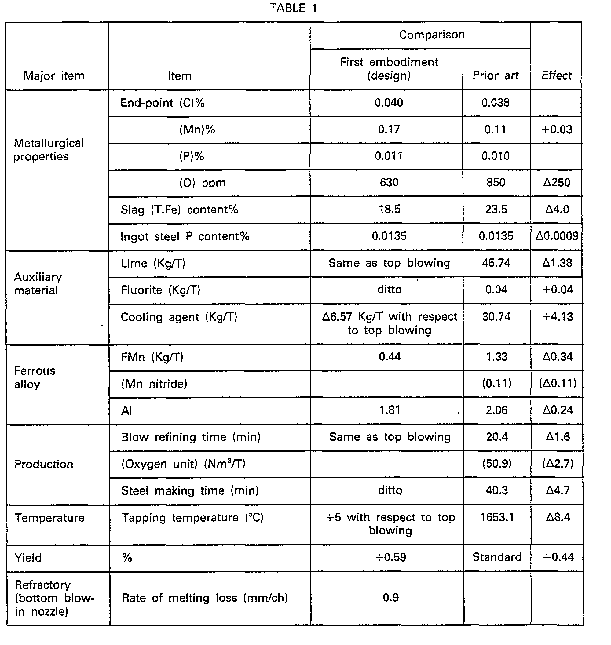
- Table 1 shows an example in which 641 channels of the molten metal refining nozzle according to Figure 1 wwere used for the combined blow refining (the top,and bottom flowing) in a converter.
- the yield is improved by 0.59% over the refining using only the top blowing and the example is also effective with respect to the ferroalloys.
- the other effects are the reduced refining time, the reduced tapping temperature, etc.
- the rate of melting loss of the conventional porous nozzle with the gas ventilation holes of 100 ⁇ or less is 2.5 to 5.0 mm/ch, while the rate of melting loss is as small as 0.8 to 0.9 mm/ch when the nozzle according to Figure 1 comprise a nonporous brick nozzle formed with holes of about 1 mmo.
- Figure 3 is a graph showing a blown-gas flow control characteristic of the nozzle according to Figure 1.
- Figure 4 is a graph showing the course of changes in the service life of the nozzle when the refining was effected under the use conditions: the nozzle material, MgO-C(C 20%); bottom blowing gas pressure, 4 to 20 Kg/Cm 2 G; flow rate, 10 to 200 Nm 3 /Hr; and types of gas, Ar, Co 2 and N 2 and the operating conditions: the tapping temperature, 1,680 to 1,685°C; and the bottom blowing pattern, as shown in Figure 6.
- Figure 5 is a graph showing the relationship between the tapping temperature and the rate of melting loss.
- Figure 7-1 is a longitudinal sectional view showing an example in which the molten metal refining nozzle according to the invention is mounted in the bottom of a molten metal vessel
- Figure 7-2 is a plan view of the molten metal refining nozzle shown in Figure 7-1.
- numeral (1) designates a refractory made of non-porous brick.
- the refractory (1) is formed with a plurality of holes (2) extending substantially straightly from its working surface or that surface which directly contacts with the molten steel on the inner side of the vessel when it is mounted in the molten metal vessel to its back or the other surface on the outer side of the vessel.
- Numeral (3) designates a metal cover which is constructed to enclose the sides of the refractory (1 The lower end of the metal cover (3) is extended beyond the lower end of the refractory (1) to define a gas reservoir space (4) enclosed by an upper metal plate (5) and a lower metal plate (6).
- the upper metal plate (5) is formed with a plurality of holes which are each communicated with one of the holes (2) at the contacting place therewith and thus the blowing of gas is not impeded at all.
- the holes (2) are divided into holes (2') having a smaller diameter and arranged on the outer side and holes (2") having a larger diameter and arranged on the inner side.
- Numeral (7) designates a gas induction pipe through which gas is blown into the molten metal vessel via the pressure box (4).
- Numeral (8) designates an outer sleeve for firmly mounting the molten metal refining nozzle in a set brick (9) and a shell (10) of the molten metal vessel.
- the molten metal refining nozzle in accordance with the invention is constructed as described above and the holes (2') arranged on the outer side are smaller in diameter than the holes (2") arranged on the inner side, it is possible to overcome the disadvantages of the nozzles where the holes (2) are of substantially the same diameter, that is, the shape of the mushroom on the working surface (the layer formed in mushroom shape by the molten material in the vessel along the working surface in front of the holes) becomes unstable in shape so that the resulting melting loss increases and the direction of blowing becomes unstable.
- mushroom will take an ideal from when a refractory having a hole of the double pipe construction of Figure 8(a) (the outer pipe passes a cooling gas and the inner pipe passes an intended gas) is used such that the molten material (M) in the vessel forms a layer of mushroom shape on the working surface in front of the hole and the blowing gas is introduced in the directions of the arrows shown in the Figure.
- the holes (2) have substantially the same diameter as shown in Figure 8(b)
- the molten material (M) in the vessel forms a layer of an unstable shape so that there is the danger of the holes (2) being clogged and there is also the danger of the gas being blown unstably .as indicated by the arrows in the Figure.
- the nozzle according to the invention has a very slow rate of melting loss and is capable of a wider range of flow control during the gas blowing thereby not only improving the refining effect but also further increasing the service life of the nozzle itself.
- porous plugs each comprising a porous refractory having a gas induction pipe attached thereto
- special devices which will be described later are used in the case of travel type vessels.
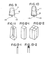
- Figures 9 and 10 are sectional views of these porous plugs in which numeral (11) designate porous refractories, (12) gas sealing coatings or shells, (13) bottom shells, and (14) gas induction pipes.
- a hole is formed through a refractory (see Figure 11), refractories are assembled to form a hole therethrough (see Figures 12-1 and 12-2) or a single or double tubes are embedded in a refractory to blow gas through the openings thereof (see Figures 13-1 and 13-2).
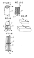
- the nozzles adapted for use with the stationary type vessels include a nozzle of the construction shown in Figures 15-1 and 15-2.
- Figure 4 shows the previously mentioned special device used with the travel type vessels.
- the parts designated by the same reference numerals as Figures 9 and 10 indicate that they comprise the same component parts.
- Numeral (15) designates small pipes, (16) a nonporous refractory nozzle, (17) a gas pressure equalizing chamber, and (18) a gas sealing coating or shell.
- the conventional porous plug causes gas to pass through the pores in the brick structure, its gas flow rate is low and its melting loss resisting property also cannot be said as excellent.
- the plug is wholly composed of a refractory, the occurrence of spallings, cracks or the like tends to cause a variation in the gas flow rate and it is also difficult to manufacture large gas blowing bricks.
- a gas blowing nozzle having metal tubes embedded therein to provide holes therethrough can be said as one that can be used with a stationary type vessel whose vessel inner refractory has a service life of over several hundred times so as to be balanced in loss with other refractories and ensure a reduced variation in the gas flow rate.
- the gas flow rate is proportional to the pipe diameter and the number of the tubes and flow resistance is presented if the tubes are long. While the gas flow rate is practically proportional to the sum of the bore cross-sectional areas of the tubes making it possible to ensure a large gas flow rate with a small number of large-diameter tubes, if the range of the required gas flow rates is large and there are also needs to use low flow rates, there are problems in that the molten metal tends to enter the large-diameter tubes with the result that the molten metal solidifies in the tubes or flows out through the tubes and so on.
- a gas blowing nozzle of a type to which the invention can be applied as described above in relation to Figures 7-1 and 7-2 and which overcomes these deficiencies, comprises a refractory nozzle which is mounted on a stationary type molten metal vessel capable of continuous gas blowing so as to blow gas into the molten metal in the vessel and is constructed so that a large number of small tubes are provided in the nozzle to pass the gas therethrough.
- numeral (16) designates a non-porous refractory nozzle, and (15) a large number of small tubes disposed in the refractory nozzle to pass gas and each consisting of a heat-resisting steel tube such as a stainless steel tube.
- Numeral (17) designates a gas pressure equalizing chamber. While this portion must be filled with a stopping material when the conventional nozzle of Figure 14 is used with a travel type vessel, the present nozzle is used with a stationary vessel so that gas is blown without interruption and therefore no stopping material is needed.
- Numeral (12) designates a gas sealing coating or shell.
- Figure 16 shows a nozzle including two units of the nozzle of Figure 15 which are arranged one upon another.
- the inner diameter of the small tubes (15) is selected 0.5 to 3.0 mm in the above mentioned basic construction
- this limitation of the inner diameter of the small tubes (15) is due to its dual function of preventing the entry of the molten metal into the small tubes (15) and ensuring the blowing of a large amount of gas and thus, if the diameter is not exceeding 0.5 mm, it is not preferable since the essential object of the small tubes (15) is not attained, that is, the flow rate of blowing gas is reduced excessively, while on the other hand, if the diameter is over 3.0 mm, the entry of the molten metal cannot be avoided.
- the third embodiment of the invention also features that the number of the small tubes (15) provided in the nonporous refractory nozzle (16) is selected 10 to 150 and this limitation to the number of the small tubes (15) has the purpose of ensuring the blowing of a large amount of gas required for the efficient refining in the molten metal vessel; thus, the upper and lower limits to the tube number represent the optimum range for this purpose.
- the nozzle comprises a plurality of nozzle units arranged in stages and this limitation is provided such that different nozzles of given lengths are assembled in stages as occasion demands with the resulting merits with respect to the flow rate of blowing gas, the service life, the manufacturing cost, etc.
- the entire length of the nozzle (excluding the gas induction pipe) is selected 500 mm or over and this limitation is due to the fact that the refractory lining of a stationary large molten metal vessel is as thick as over 500 mm and therefore it is necessary to prepare nozzles having a length of 1,000 mm or 1,500 mm.
- the presses used for producing (forming) such long unitary type nozzles include the friction screw press, the hydraulic press, the isostatic press, etc. While the friction screw press of as large as 1,000 ton/cm 2 is available, the equipment cost of this type is excessively high and the size is also excessively large. Also, there is no hydraylic press having the equivalent capacity to the friction screw press and generally it is considered that every ton of the friction screw press corresponds to every three tons of the hydraulic press thus making it undesirable to use the hydraulic press.
- the isostatic press is a forming machine whose capacity is about 1.5 ton/cm 2 at the maximum and a nozzle having a very high bulk density was produced by forming a refractory composition of MgO 80% by weight C 20% by weight into a nozzle of 1,500 mm in length and disposing scatteringly arranged small hole tubes in the refractory.
- the following table shows the comparisons with the case using the fraction screw press of 1,000 ton/cm 2 . In other words, in Figure 17, if the areas to be formed are S l ⁇ S 2 and if the pressure P of the press is constant, then there results P 1 >P 2 in the case of the friction screw press.
- Figure 18 shows the examples in which the blowing nozzles of the comparative cases in the above table were fitted in the bottom of a 250-ton converter.
- the comparative case 3 shows the minimum rate of melting loss and the increased bulk density by the friction screw press has the effect of reducing the rate of melting loss.
- the assembled nozzle has a dense structure, reduces the decarbonization loss in the case of the previously mentioned MgO-C brick and improves the wear-resisting properties due to the intensified structure.
- Another molten metal refining nozzle refractory adapted for installation in the bottom of the like of a molten metal refining furnace has a chemical composition comprising C 5 to 30% and the remainder comprising one or more elements selected from MgO, AI203, CaO, Cr 2 0 3 and ZrO 2 .
- the carbon content in the chemical composition of the nozzle refractory is selected between 5 and 30% on the ground that the lower limit of less than 5% not only increases the penetration of the slag with the resulting increase in the melting loss but also increases the damage due to the thermal spalling and the upper limit of over 30% deteriorates the nozzle in terms of the strength and corrosion resistance.
- the reason for including one or more of MgO, A1 2 0 3 , CaO, Cr 2 0 3 and Zr0 2 in the chemical composition of the nozzle refractory is to improve the quality of the refractory and thereby improve the resistance to spalling, resistance to wear, strength, etc.
- the raw materials used for the nozzle refractory are also shown as follows.
- This construction covers all of the calcined, uncalcined and calcined and pitch impregnated nozzles using the above-mentioned ingredients as the principal components and in this case the manufacturing method of refractory consists of the ordinary method.
- the rate of melting loss is reduced to as low as 0.8 to 0.9 mm/ch and hence the service life is increased.
- a refining method makes possible under the proper top and bottom blowing conditions the refining of high carbon steel which has heretofore been impossible with a top and bottom blowing converter due to the fact that the stirring by the bottom-blown gas is intense and it is impossible to ensure the (T.Fe) and oxygen potential in the slag thus deteriorating the removal of phosphorus.
- top and bottom blowing refining method in which gas is blown into the metal bath through the bottom of a converter so as to stir the metal bath and thereby improve the operating efficiency and the metallurgical performance.
- the bottom blowing nozzles which have been put in practical use generally include the pipe type such as SUS pipes and the porous brick type.
- the diameter is 5 to 20 mm and the gas flow rate must be greater than the speed of sound at the outlets; if the flow rate is lower than this, the nozzle clogging is caused. This is the essential condition that must be ensured so far as the molten metal is present.
- the limit of the pressures used industrially in this type of processes is on the order of 30 Kg/cm 2 and this range corresponds to the control range for the bottom-blown gases.
- the lower limit of the bottom-blown gases is determined by the nozzle clogging and the upper limit is determined by the equipment pressure limit.
- the range from the lower limit flow rate to the upper limit flow rate is about 2 to 3 times.
- the porous nozzle type using the porous brick is formed with a refractory material having its grain size controlled to come into a certain range and therefore the gas vent holes are practically of 100 ⁇ or less; therefore, even if the gas blow is stopped with the molten steel remaining in the converter, there is practically no entry of the molten metal into the pores and the previously mentioned problems of the pipe type are overcome.
- the gas flows through between the crystal grains of the refractory so that the resistance is very great there and the gas pressure must be maintained high in order to effect the gas control easily; if the gas pressure is increased, the nozzle is damaged greatly due to it being made of a refractory and the upper limit of the gas pressure is on the order of 30 Kg/cm 2 . Also, the flow of the gas between the grains has the disadvantage of considerably deteriorating the service life of the porous nozzle itself.
- high carbon steel may be produced by a top and bottom blowing converter in which nozzles each comprising a non-porous refractory formed with a large number of small-diameter holes are mounted in the bottom of the converter or in the furnace wall below the molten metal level and a bottom-blown gas of 0.001 to 0.20 Nm 3 /min.T is blown from the nozzles while maintaining a pressure higher than the molten steel plus slag static pressure.
- the refining is effected by using nozzles of a particular type and blowing a particular amount of bottom-blown gas so as to promote the dephosphorization required for the production of steel by a top and bottom blowing converter and ensure the proper amount of (T.Fe) contained in the slag and the proper oxygen potential and which ensures 10% or more of the (T.Fe) content as shown in Figure 19 and minimizes the amount of iron loss.
- Figure 19 is a graph showing the relationship between the flow rate of bottom-blown gas and the dephosphorization efficiency in the high carbon range.
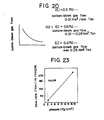
- Figure 20 is a graph showing the optimum bottom-blown gas quantities in accordance with the end-point C levels.
- the amount of bottom-blown gas required for the refining of high carbon steel is selected properly in accordance with the desired end-point carbon level on the basis of the technical details shown in the above Figures.
- Figure 21 shows an example of a bottom blowing nozzle of a type with which the invention is concerned and used with the above described refining method.
- numeral (1) designates a refractory made of nonporous brick, (2) a large number of small-diameter holes formed in the refractory (1) therethrough, (3) a metal cover comprising a shell covering the sides of the refractory (1), (4) a pressure box, (5) an upper metal plate, (6) a lowec metal plate, (7) a gas induction pipe and (8) an outer sleeve.
- Figure 22 shows an example of mounting positions of the above-mentioned nozzles in the converter bottom.
- numeral (19) designates the converter bottom, and (20) the mounting positions of the bottom blowing nozzles. Note that while the number of the nozzles is four in this case, the number of nozzles is not limited to four.
- Figure 23 is a graph showing a flow characteristic obtained when gas is blown into the converter through the bottom blowing nozzle, that is, the relationship between the pressure and flow rate of the blowing gas.
- Figure 24 is a graph showing the relationship between the flow rate of bottom-blown gas and the end-point [C] and the end-point [P]
- Figure 25 is a graph showing the relationship between the flow rate of bottom-blown gas and the end-point [C] and T.Fe.
- Table 2 shows by way of examples the materials and some details of the construction of the bottom blowing nozzles
- Table 3 shows the bottom blowing conditions
- Table 4 shows a top-blown oxygen pattern and a bottom-blown pattern.
- a known method of controlling the nitrogen (N) content in ingot steel consists of detecting the level of nitrogen in the molten iron (the nitrogen level in the molten steel after the blow refining as the case may be) and charging FMn nitride during the tapping.
- Figure 26 shows the [N] contents of the ingot steel obtained by performing the combined blow refining in a converter on the basis of the [N] levels in the molten iron which were estimated in terms of the [Ti] levels in the molten iron.
- Figure 27 shows the steel N vp (ppm) due to the blown N 2 gas
- Figure 28 shows the relationship between the blown N 2 gas unit and the pickup [N] quantity in accordance with the sixth embodiment of the invention
- Figure 29 shows the desired [N] ppm-molten iron [N] ppmxconverter denitration factor and the nitrogen gas Nm 3 /T.
- the N content of the molten steel in the converter increases in proportion to the bottom blown N 2 gas unit.
- N 2 gas is used as the bottom-blown gas for the combined blow refining with the result that not only the control of the end-point [N] content is made possible in addition to the effect of the combined blow refining but also the necessity for the introduction of FMn nitride is eliminated.
- the double slag process has heretofore been used to produce low phosphorus steel by the converter blow refining and this process also involves the following problems.
- low phosphorus steel can be produced by a top and bottom blowing converter comprising maintaining the basicity (CaO/Si0 2 ) of the slag to 4.0 or over, keeping the flow rate of bottom-blown gas to 0.07 Nm 3 /min ton or less from the beginning of blow refining until at least the carbon content of molten steel attains 0.4%, then maintaining the flow rate of the bottom-blown gas at 0.05 Nm 3 /min ton during the refining until the desired carbon content of the molten steel is reached and effecting further only the blowing of the bottom-blown gas after the completion of the blow refining thereby promoting the removal of the phosphorus from the molten steel.
- a top and bottom blowing converter comprising maintaining the basicity (CaO/Si0 2 ) of the slag to 4.0 or over, keeping the flow rate of bottom-blown gas to 0.07 Nm 3 /min ton or less from the beginning of blow refining until at least the carbon content of molten steel attains 0.
- the end-point [P] end-point of 0.006% can be ensured by the [P] input of 0.120% and it is possible to ensure the ingot steel [P] content of 0.012% in consideration of the recovered phosphorus from the slag and the pickup from the alloys.
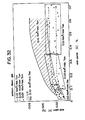
- Figure 32 is a graph showing the relationship between the flow rate of bottom-blown gas and the end-point [C] and [P] contents
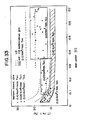
- Figure 33 is a graph showing the relationship between the flow rate of bottom-blown gas and the end-point [C] content and the T.Fe content.
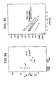
- Figure 34 is a graph showing the changes in the [P] content before and after the rinse
- Figure 35 is a graph showing the temperature drop due to the rinse
- Figure 36 is a graph showing the changes in the slag composition due to the rinse.
- the dephosphorization equilibrium after the rinse conforms with the previously mentioned dephosphorization equilibrium equation due to the slag composition (basicity) and the [P] and (P 2 0 5 ) contents after the rinse, and there is a condition which promotes the dephosphorization further due to the increased (CaO) despite the decreased (T.Fe) content in the slag composition and the decrease in the slag temperature caused by the rinse.
- This method makes possible the production of low phosphorus steel in the top and bottom blowing converter using the single slag process and this has the effect of reducing the steel-making time considerably as compared with conventional methods.
Landscapes
- Engineering & Computer Science (AREA)
- Chemical & Material Sciences (AREA)
- Manufacturing & Machinery (AREA)
- Materials Engineering (AREA)
- Metallurgy (AREA)
- Organic Chemistry (AREA)
- Mechanical Engineering (AREA)
- Carbon Steel Or Casting Steel Manufacturing (AREA)
- Treatment Of Steel In Its Molten State (AREA)
Description
- A first embodiment of the present invention relates to a molten metal refining nozzle which is mounted for example in the bottom of a molten metal refining furnace for blowing gas therethrough and its object is to increase the flow control range of the refining nozzle during the gas blowing and also to increase the service life of the nozzle itself.
- It has been well known in the art that for the purpose for example of refining, degassing or stirring molten metal, gas blowing refractory nozzles are mounted mainly in the bottom of a molten metal vessel and various kinds of gasses are blown into the molten metal through the nozzles. Also, recently it has been known to blow gas into a refining furnace such as a converter through its bottom by means of the gas blowing nozzles made of refractory material and the nozzles for this purpose have been proposed by the group of the inventors, etc., in Japanese Patent Application No. 56-84321 and Japanese Utility Model Application No. 56-125950.
- However, the latter investigations of these proposed nozzles have shown that the following problems are encountered.
- (i) In the case of a gas blowing refractory formed with a large number of holes therethrough, the melting loss of the nozzle refractory increases with decrease in the spacing between the holes.
- (ii) Where each of the holes in the gas blowing refractory is provided by a steel tube embedded in the refractory, the steel tubes will be crushed during the manufacture if the wall thickness is thin and the melting loss will be increased during the use if the wall thickness is large.
- (iii) In the case of an equipment including a pressure box in the lower part of the gas blowing refractory, the flow of the blown gas will be deteriorated and the melting loss will be increased if the distance between the upper and lower steel plates forming the pressure box is too small.
- (iv) The service life and manufacturing cost of the nozzle will be affected adversely if the thickness of the metal cover enclosing the sides of the gas blowing refractory is not proper.
- (v) If the chemical composition of the gas blowing refractory is not proper, the penetration of the molten steel and slag will increase and also the damage due to thermal spalling will be increased.
- In order to overcome these problems, a molten metal refining nozzle comprises a refractory having a plurality of holes extending from its working surface to its back, a metal cover enclosing the sides of the refractory, and a pressure box provided in the bottom of the refractory so as to communicate with the holes and define a gas reservoir space. JP-A-55-149750 and EP-A-0,021,861 illustrate examples of such a construction.
- However, the following problems have been found by the further investigations of the proposed nozzles.
- (i) Where the holes in the gas blowing refractory are all substantially equal in diameter, the mushroom formed on the working surface (the layer of the vessel molten metal covering in mushroom shape along the working surface in front of the holes) becomes unstable in shape, the melting loss is increased, the gas blowing direction becomes unsteady and the control range of the gas flow rate is decreased thus tending to cause clogging of the holes.
- The invention seeks to solve the foregoing unsolved problems of the molten metal refining nozzle for gas blowing purposes and it provides measures to overcome these problems.
- The invention provides a bottom-blown gas blowing nozzle for a molten metal refining furnace, comprising a refractory including a plurality of holes formed therethrough to extend from a working surface to a bottom surface thereof, a metal cover enclosing a part or whole of the sides of said refractory and a pressure box formed at the bottom portion of said refractory so as to communicate with said holes and define a gas reservoir, characterised in that the refractory includes a first group of a plurality of holes extending therethrough and a second group of a plurality of holes extending therethrough and surrounding said first group of holes, the diameter of each hole of said second group thereof being smaller than that of each hole of said first group thereof.
- The spacing between the plurality of holes in the refractory is preferably selected not less than 3 mm and not greater than 150 mm.
- Each of the plurality of holes in the refractory is preferably provided by a metal tube embedded in the refractory and the wall thickness of the metal tubes is selected not less than 0.1 mm and not greater than 10 mm.
- The metal cover preferably comprises a steel plate having a thickness of not less than 0.1 mm and not greater than 5 mm.
- The distance between the upper and lower metal plates defining the gas reservoir space of the pressure box is preferably selected not less than 2 mm and not greater than 50 mm.
- In the drawings:-
- Figure 1 is a longitudinal view showing an example of a molten metal refining nozzle of the type with which the invention is concerned;
- Figure 2 is a plan view of the nozzle;
- Figure 3 is a graph showing a flow control characteristic of the nozzle of Figure 1;
- Figure 4 is a graph showing changes in the rate of melting loss of the nozzle;
- Figure 5 is a graph showing changes in the rate of melting loss of the nozzle;
- Figure 5 is a graph showing the relationship between the rate of melting loss of the nozzle and the tapping temperature;
- Figure 6 is a graph showing the bottom blowing pattern in the tests, the data of which are shown in Figure 4;
- Figure 7-1 is a longitudinal sectional view showing an example of a molten metal refining nozzle according to an embodiment of the invention;
- Figure 7-2 is a plan view of the nozzle;
- Figure 8 shows sectional views showing the conditions of mushrooms produced by the molten material in the vessel at the front of the nozzle holes;
- Figures 9 and 10 are sectional views of prior art porous plugs;
- Figures 11, 12 and 13 are perspective views of conventional nozzle holes;
- Figure 14 is a sectional view of a conventional nozzle used in a transport vessel;
- Figure 15-1 is a perspective view of a nozzle;
- Figure 15-2 is a sectional view of Figure 15-1;
- Figure 16 is a sectional view of another nozzle arrangement;
- Figure 17 is a diagram showing the relationship between the pressure of a press and the areas and densities of formed products;
- Figure 18 is a graph showing the rate of melting loss of the nozzle of Figure 15;
- Figure 19 is a graph showing the relationship between the flow rate of bottom-blown gas and the dephosphorization performance in a high carbon range;
- Figure 20 is a graph showing the relationship between the end-point [C] level and the flow rate of bottom-blown gas;
- Figure 21 is a sectional view showing another bottom blowing nozzle of the type with which the invention is used;
- Figure 22 is a plan view showing an example of the mounting positions of the bottom blowing nozzles in the bottom of a converter;
- Figure 23 is a graph showing the relationship between the flow rate and pressure of gas introduced from the bottom blowing nozzle;
- Figure 24 is a graph showing the relationship between the flow rate of bottom-blown gas and the end-point [C] and [P] contents;
- Figure 25 is a graph showing the relationship between the flow rate of bottom-blown gas and the end-point [C] and T.Fe contents;
- Figure 26 is a graph showing an example of controlling the N content by the addition of N2 gas;
- Figure 27 is a graph showing the N2 gas unit and the Ti% and [N] content;
- Figure 28 is a graph showing the relationship between the N2 gas unit and the amount of pickup [N];
- Figure 29 is a graph showing the relationship between the (desired [N] content-[N] content of molten iron x converter denitration rate) and the blown nitrogen gas;
- Figure 30 is a graph showing the relationship between the actual results of the dephosphorization equilibrium by combined blow refining;
- Figure 31 is a graph showing the relationship between the [P] input and the [P] content of steel;
- Figure 32 is a graph showing the relationship between the flow rate of bottom-blown gas and the end-point [C] and the end point;
- Figure 33 is a graph showing the relationship between the bottom-blown gas and the end-point [C] and T.Fe contents;
- Figure 34 is a graph showing the relationship between the [P] contents before and after the rinse;
- Figure 35 is a graph showing the relationship between the rinse time and the temperature of the molten steel in the furnace; and
- Figure 36 is a graph showing the relationship between the (T.Fe) contents before and after the rinse.
- Generally in the constructions illustrated in the drawings, (1) is a refractory made of non-porous brick, (2) is a nozzle hole, (2') is a nozzle hole of a radially outer series thereof, (2") is a nozzle hole of a radially inner series thereof, (3) is a metal cover, (4) is a pressure box, (5) is an upper metal plate, (6) is a lower metal plate, (7) is a gas induction pipe, (8) is an outer sleeve, (9) is a set brick, (10) is a shell, (11) is a porous refractory, (12) is a gas sealing coating material or shell, (13) is a bottom shell, (14) is a gas induction pipe, (15) is a small tube, (16) is a non-porous refractory nozzle, (17) is a gas pressure equalizing chamber, (18) is a gas sealing coating, (19) is a converter bottom, and (20) represents a mounting position of bottom blowing nozzle.
- The molten metal refining nozzle according to Figure 1 will now be described and is of a type to which the invention can be applied as described below with reference to Figures 7-1 and 7-2. This shows an example in which a molten metal refining nozzle is mounted in the bottom of a molten metal vessel, and Figure 2 is a plan view of the molten metal refining nozzle. In the Figures, numeral (1) designates a refractory made of porous brick. The refractory (1) is formed with a plurality of holes (2) extending from its working surface or that surface which contacts with the molten metal on the inner side of the vessel when it is mounted in the molten metal vessel to its back or that surface outside of the vesset and the holes extend substantially straightly. Numeral (3) designates a metal cover constructed to enclose a part or the whole of the sides of the refractory (1). The lower end of the metal cover (3) extends through the lower end of the refractory (1) to define a gas reservoir space (4) enclosed by an upper metal plate (5) and a lower metal plate (6). Note, that the upper metal plate (5) is formed with a plurality of holes each communicating with one of the plurality of holes (2) of the contacting place therebetween and thus the blowing of gas is not impeded. Numeral (7) designates a gas induction pipe by which gas is blown into the molten metal vessel by way of the pressure box (4). Numeral (8) designates an outer sleeve provided to firmly mount the molten metal refining nozzle in a set brick (9) and a steel shell (10) of the molten metal vessel. Note that the outer sleeve is provided to prevent for example the breaking of the nozzle during the transport, etc.
- In this construction the spacing between the holes (2) formed in the refractory (1) is selected not less than 3 mm and not greater than 150 mm.
- By so doing, it is possible to greatly reduce the melting loss of the nozzle refractory which has heretofore been the problem in cases where the spacing between the holes is small as in conventional nozzle refractories. The reason for detecting the spacing between 3 mm and 150 mm is that if the spacing is not exceeding 3 mm, the previously mentioned effects cannot be obtained, whereas if the spacing is over 150 mm, the area occupied by the holes (2) is too small compared with the area of the refractory (1) and hence the amount of gas blown is reduced with the resulting decrease in the control range of flow rate.
- If the plurality of holes (2) in the refractory (1) are each composed of a metal tube embedded in the refractory (1 the wall thickness of the metal tubes is selected not less than 0.1 mm and not greater than 10 mm.
- In this way, it is possible to prevent crushing of the metal tubes during the manufacture which occurs frequently when the wall thickness of the metal tubes is as small as not exceeding 0.1 mm and it is also possible to prevent the melting loss from being increased due to the embedding of the metal tubes when the wall thickness is excessively great exceeding 10 mm.
- The metal cover (3) is made of a steel plate having a thickness of not less than 0.1 mm and not greater than 5 mm.
- In this way, it is possible to ensure the essential functions of the metal cover (3), that is, the prevention of gas leakage from the sides of the refractory (1) other than the holes (2) and the pressure loss of the blown gas; to ensure these functions and the desired service life of the nozzle, the lower limit to the thickness of the steel plate of a suitable material must be selected 0.1 mm and the upper limit must be selected 5 mm in order to prevent increase in the manufacturing cost of the nozzle.
- The distance between the upper and lower steel plates (5) and (6) defining the gas reservoir space of the pressure box (4) is selected not less than 2 mm and not greater than 50 mm.
- Thus, in order to overcome problems with conventional nozzles that is, the deterioration of the blown gas flow as well as the reduced flow control range and the increased pressure loss due to the excessively small distance between the upper and lower steel plates, it is advantageous to select the lower limit of the distance to be 2 mm, and it is also necessary to select the
upper limit 5 mm in order to make the nozzle compact. - By so doing, it is possible to overcome the problem of the increased slag penetration due to the improper chemical composition of the conventional gas blowing refractory, the problem of the increased damage due to the thermal spalling, etc. Then, the lower limit of the carbon content in the chemical composition is selected 5% because the penetration of the molten metal and the slag increases and the melting loss of the refractory increases if the carbon content is less than this value, and also the reason for selecting the
upper limit 30% is that the strength and corrosion resistance of the refractory are deteriorated if the carbon content is greater than this upper limit. - The following Table 1 shows an example in which 641 channels of the molten metal refining nozzle according to Figure 1 wwere used for the combined blow refining (the top,and bottom flowing) in a converter. As will be seen from Table 1, the yield is improved by 0.59% over the refining using only the top blowing and the example is also effective with respect to the ferroalloys. The other effects are the reduced refining time, the reduced tapping temperature, etc. It will be seen from the Table that as regards the rate of refractory melting loss, the rate of melting loss of the conventional porous nozzle with the gas ventilation holes of 100 µ or less is 2.5 to 5.0 mm/ch, while the rate of melting loss is as small as 0.8 to 0.9 mm/ch when the nozzle according to Figure 1 comprise a nonporous brick nozzle formed with holes of about 1 mmo.
- Figure 3 is a graph showing a blown-gas flow control characteristic of the nozzle according to Figure 1.
- Figure 4 is a graph showing the course of changes in the service life of the nozzle when the refining was effected under the use conditions: the nozzle material, MgO-C(
C 20%); bottom blowing gas pressure, 4 to 20 Kg/Cm2 G; flow rate, 10 to 200 Nm3/Hr; and types of gas, Ar, Co2 and N2 and the operating conditions: the tapping temperature, 1,680 to 1,685°C; and the bottom blowing pattern, as shown in Figure 6. - Figure 5 is a graph showing the relationship between the tapping temperature and the rate of melting loss.
- In the case of Figures 4 and 5, the rate of melting loss is greater when the bottom-blown gas, is CO2 than when the gas is Ar on the following ground


- It is considered that the carbon in MgO-C is reduced by FeO and thus MgO is directly lost by melting. (The Fe(I) layer of 0.5 to 1.0 mm is present on the working surface).
- As a result, considerations are given, such as, the addition of a proper amount of carbon to C in the MgO-C, the improvement of the purity of C (95 to 99%) and the improvement of the purity of MgO.
- As will be apparent from the above-described example, in accordance with the molten metal refining nozzle of Figure 1 a wide range of flow control is possible for the blowing of gas thereby not only improving the refining effect but also increasing the service life of the nozzle itself.
- A molten metal refining nozzle according to the invention will now be described with reference to the drawings. Figure 7-1 is a longitudinal sectional view showing an example in which the molten metal refining nozzle according to the invention is mounted in the bottom of a molten metal vessel, and Figure 7-2 is a plan view of the molten metal refining nozzle shown in Figure 7-1. In the Figures, numeral (1) designates a refractory made of non-porous brick. The refractory (1) is formed with a plurality of holes (2) extending substantially straightly from its working surface or that surface which directly contacts with the molten steel on the inner side of the vessel when it is mounted in the molten metal vessel to its back or the other surface on the outer side of the vessel. Numeral (3) designates a metal cover which is constructed to enclose the sides of the refractory (1 The lower end of the metal cover (3) is extended beyond the lower end of the refractory (1) to define a gas reservoir space (4) enclosed by an upper metal plate (5) and a lower metal plate (6). Note that the upper metal plate (5) is formed with a plurality of holes which are each communicated with one of the holes (2) at the contacting place therewith and thus the blowing of gas is not impeded at all. In accordance with this embodiment of the invention, there is a feature that the holes (2) are divided into holes (2') having a smaller diameter and arranged on the outer side and holes (2") having a larger diameter and arranged on the inner side. Numeral (7) designates a gas induction pipe through which gas is blown into the molten metal vessel via the pressure box (4). Numeral (8) designates an outer sleeve for firmly mounting the molten metal refining nozzle in a set brick (9) and a shell (10) of the molten metal vessel.
- Thus, since the molten metal refining nozzle in accordance with the invention is constructed as described above and the holes (2') arranged on the outer side are smaller in diameter than the holes (2") arranged on the inner side, it is possible to overcome the disadvantages of the nozzles where the holes (2) are of substantially the same diameter, that is, the shape of the mushroom on the working surface (the layer formed in mushroom shape by the molten material in the vessel along the working surface in front of the holes) becomes unstable in shape so that the resulting melting loss increases and the direction of blowing becomes unstable. In other words, mushroom will take an ideal from when a refractory having a hole of the double pipe construction of Figure 8(a) (the outer pipe passes a cooling gas and the inner pipe passes an intended gas) is used such that the molten material (M) in the vessel forms a layer of mushroom shape on the working surface in front of the hole and the blowing gas is introduced in the directions of the arrows shown in the Figure. However, where the holes (2) have substantially the same diameter as shown in Figure 8(b), the molten material (M) in the vessel forms a layer of an unstable shape so that there is the danger of the holes (2) being clogged and there is also the danger of the gas being blown unstably .as indicated by the arrows in the Figure. On the contrary, by selecting the diameter of the holes (2') arranged on the outer side smaller than that of the holes (2") on the inner side, it is possible to form a mushroom which on the whole has substantially the same thickness and the introduced gas flows in the uniform direction thus preventing clogging of the holes and increasing the control range of flow rate.
- Compared with a nozzle of the type in which a plurality of holes of the same diameter are formed in a nonporous refractory, the nozzle according to the invention has a very slow rate of melting loss and is capable of a wider range of flow control during the gas blowing thereby not only improving the refining effect but also further increasing the service life of the nozzle itself.
- In the past, as regards nozzles adapted for blowing gas into the molten metal in molten metal vessels, porous plugs (each comprising a porous refractory having a gas induction pipe attached thereto) or special devices which will be described later are used in the case of travel type vessels. Figures 9 and 10 are sectional views of these porous plugs in which numeral (11) designate porous refractories, (12) gas sealing coatings or shells, (13) bottom shells, and (14) gas induction pipes.
- Also, in the case of stationary type vessels, as is the case with those used by such companies as AOD, RH and CLU, a hole is formed through a refractory (see Figure 11), refractories are assembled to form a hole therethrough (see Figures 12-1 and 12-2) or a single or double tubes are embedded in a refractory to blow gas through the openings thereof (see Figures 13-1 and 13-2).
- On the other hand, the nozzles adapted for use with the stationary type vessels include a nozzle of the construction shown in Figures 15-1 and 15-2. Figure 4 shows the previously mentioned special device used with the travel type vessels. In Figure 14, the parts designated by the same reference numerals as Figures 9 and 10 indicate that they comprise the same component parts. Numeral (15) designates small pipes, (16) a nonporous refractory nozzle, (17) a gas pressure equalizing chamber, and (18) a gas sealing coating or shell.
- Since the conventional porous plug causes gas to pass through the pores in the brick structure, its gas flow rate is low and its melting loss resisting property also cannot be said as excellent. There is another disadvantage that since the plug is wholly composed of a refractory, the occurrence of spallings, cracks or the like tends to cause a variation in the gas flow rate and it is also difficult to manufacture large gas blowing bricks.
- As a result, a gas blowing nozzle having metal tubes embedded therein to provide holes therethrough can be said as one that can be used with a stationary type vessel whose vessel inner refractory has a service life of over several hundred times so as to be balanced in loss with other refractories and ensure a reduced variation in the gas flow rate.
- Then, it is known that, as regards the relationship between the tubes for the holes and the blowing gas, if the type of gas and the gas pressure are fixed, the gas flow rate is proportional to the pipe diameter and the number of the tubes and flow resistance is presented if the tubes are long. While the gas flow rate is practically proportional to the sum of the bore cross-sectional areas of the tubes making it possible to ensure a large gas flow rate with a small number of large-diameter tubes, if the range of the required gas flow rates is large and there are also needs to use low flow rates, there are problems in that the molten metal tends to enter the large-diameter tubes with the result that the molten metal solidifies in the tubes or flows out through the tubes and so on.
- A gas blowing nozzle of a type to which the invention can be applied as described above in relation to Figures 7-1 and 7-2 and which overcomes these deficiencies, comprises a refractory nozzle which is mounted on a stationary type molten metal vessel capable of continuous gas blowing so as to blow gas into the molten metal in the vessel and is constructed so that a large number of small tubes are provided in the nozzle to pass the gas therethrough.
- Preferably the inner diameter of the small tubes is selected between 0.5 and 3.0 mm0.
- Preferably the number of the small tubes is between 10 and 150.
- The nozzle may comprise a plurality of nozzle units arranged in stages.
- Preferably the entire length of the nozzle (excluding a gas induction pipe) is selected 500 mm or over.
- In Figures 15-1 and. 15-2, numeral (16) designates a non-porous refractory nozzle, and (15) a large number of small tubes disposed in the refractory nozzle to pass gas and each consisting of a heat-resisting steel tube such as a stainless steel tube. Numeral (17) designates a gas pressure equalizing chamber. While this portion must be filled with a stopping material when the conventional nozzle of Figure 14 is used with a travel type vessel, the present nozzle is used with a stationary vessel so that gas is blown without interruption and therefore no stopping material is needed. Numeral (12) designates a gas sealing coating or shell. Figure 16 shows a nozzle including two units of the nozzle of Figure 15 which are arranged one upon another.
- While the inner diameter of the small tubes (15) is selected 0.5 to 3.0 mm in the above mentioned basic construction, this limitation of the inner diameter of the small tubes (15) is due to its dual function of preventing the entry of the molten metal into the small tubes (15) and ensuring the blowing of a large amount of gas and thus, if the diameter is not exceeding 0.5 mm, it is not preferable since the essential object of the small tubes (15) is not attained, that is, the flow rate of blowing gas is reduced excessively, while on the other hand, if the diameter is over 3.0 mm, the entry of the molten metal cannot be avoided.
- The third embodiment of the invention also features that the number of the small tubes (15) provided in the nonporous refractory nozzle (16) is selected 10 to 150 and this limitation to the number of the small tubes (15) has the purpose of ensuring the blowing of a large amount of gas required for the efficient refining in the molten metal vessel; thus, the upper and lower limits to the tube number represent the optimum range for this purpose.
- The nozzle comprises a plurality of nozzle units arranged in stages and this limitation is provided such that different nozzles of given lengths are assembled in stages as occasion demands with the resulting merits with respect to the flow rate of blowing gas, the service life, the manufacturing cost, etc.
- The entire length of the nozzle (excluding the gas induction pipe) is selected 500 mm or over and this limitation is due to the fact that the refractory lining of a stationary large molten metal vessel is as thick as over 500 mm and therefore it is necessary to prepare nozzles having a length of 1,000 mm or 1,500 mm.
- The presses used for producing (forming) such long unitary type nozzles include the friction screw press, the hydraulic press, the isostatic press, etc. While the friction screw press of as large as 1,000 ton/cm2 is available, the equipment cost of this type is excessively high and the size is also excessively large. Also, there is no hydraylic press having the equivalent capacity to the friction screw press and generally it is considered that every ton of the friction screw press corresponds to every three tons of the hydraulic press thus making it undesirable to use the hydraulic press.
- On the other hand, the isostatic press is a forming machine whose capacity is about 1.5 ton/cm2 at the maximum and a nozzle having a very high bulk density was produced by forming a refractory composition of
MgO 80% byweight C 20% by weight into a nozzle of 1,500 mm in length and disposing scatteringly arranged small hole tubes in the refractory. The following table shows the comparisons with the case using the fraction screw press of 1,000 ton/cm2.
- Figure 18 shows the examples in which the blowing nozzles of the comparative cases in the above table were fitted in the bottom of a 250-ton converter. As will be seen from the Figure, the
comparative case 3 shows the minimum rate of melting loss and the increased bulk density by the friction screw press has the effect of reducing the rate of melting loss. - In this connection, where the nozzle is constructed by assembling a plurality of unit nozzles in stages as shown in Figure 16, it is a matter of course that separately formed refractories are connected by means of a gas equalizing chamber (17).
- As compared with the long unitary construction nozzle, the assembled nozzle has a dense structure, reduces the decarbonization loss in the case of the previously mentioned MgO-C brick and improves the wear-resisting properties due to the intensified structure.
- While the similar bulk density can be obtained by installing a press having the correspondingly increased size and capacity, the equipment cost amounts to an enormous cost and also an expense is needed for the maintenance of the drive. This nozzle eliminates such cost and expense and it also makes possible the production of the equivalent product.
- It has been well known in the art that for the purpose for exmaple of refining, degassing or stirring molten metal, gas blowing refractory nozzles are mounted mainly in the bottom of a molten metal refining furnace and various kinds of gases are blown into the molten metal through the nozzles. Also, recently it has been known to blow gas into a refining furnace such as a converter through its bottom by means of the gas blowing nozzles made of refractory material. Then, there is a problem that if the chemical composition of the nozzle refractories is not proper, the penetration of the molten metal and slag increases and also the damage due to the thermal spalling increases.
- Another molten metal refining nozzle refractory adapted for installation in the bottom of the like of a molten metal refining furnace, has a chemical
composition comprising C 5 to 30% and the remainder comprising one or more elements selected from MgO, AI203, CaO,Cr 203 and ZrO2. - The carbon content in the chemical composition of the nozzle refractory is selected between 5 and 30% on the ground that the lower limit of less than 5% not only increases the penetration of the slag with the resulting increase in the melting loss but also increases the damage due to the thermal spalling and the upper limit of over 30% deteriorates the nozzle in terms of the strength and corrosion resistance.
- Also, in this nozzle the reason for including one or more of MgO,
A1 203, CaO,Cr 203 and Zr02 in the chemical composition of the nozzle refractory is to improve the quality of the refractory and thereby improve the resistance to spalling, resistance to wear, strength, etc. - The raw materials used for the nozzle refractory are also shown as follows.
- [Oxides] MgO, CaO, MgO.CaO, Zr02,
AI 203,Cr 203, MgO.AI203 - [Carbon and carbides] C, Sic, ZrC, Wc, WoC, B4C
- [Nitrides] Si3N4, BN
- This construction covers all of the calcined, uncalcined and calcined and pitch impregnated nozzles using the above-mentioned ingredients as the principal components and in this case the manufacturing method of refractory consists of the ordinary method.
- With this nozzle refractory if the nozzle refractory is formed with a plurality of holes of about 1 mm, the rate of melting loss is reduced to as low as 0.8 to 0.9 mm/ch and hence the service life is increased.
- A refining method makes possible under the proper top and bottom blowing conditions the refining of high carbon steel which has heretofore been impossible with a top and bottom blowing converter due to the fact that the stirring by the bottom-blown gas is intense and it is impossible to ensure the (T.Fe) and oxygen potential in the slag thus deteriorating the removal of phosphorus.
- It has been well known that due to the recent increase in the size of top-blown converters, a so-called top and bottom blowing refining method is used in which gas is blown into the metal bath through the bottom of a converter so as to stir the metal bath and thereby improve the operating efficiency and the metallurgical performance.
- On the other hand, the bottom blowing nozzles which have been put in practical use generally include the pipe type such as SUS pipes and the porous brick type.
- In the case of the pipe type, generally the diameter is 5 to 20 mm and the gas flow rate must be greater than the speed of sound at the outlets; if the flow rate is lower than this, the nozzle clogging is caused. This is the essential condition that must be ensured so far as the molten metal is present. As regards the upper limit, the limit of the pressures used industrially in this type of processes is on the order of 30 Kg/cm2 and this range corresponds to the control range for the bottom-blown gases.
- In other words, the lower limit of the bottom-blown gases is determined by the nozzle clogging and the upper limit is determined by the equipment pressure limit. The range from the lower limit flow rate to the upper limit flow rate is about 2 to 3 times.
- Metallurgically, as the bottom-blown gas flow rate is increased, the reaction of the molten metal and the slag is improved and the dephosphorization is promoted; in the case of low carbon material (C=0.04% or less), the phosphorous contsnp is decreased with increase in the gas flow rate. In the case of high carbon material (C=0.40 or over), the slag and the metal are stirred excessively so that the oxidation potentials in the metal and the slag are decreased and the dephosphorization is deteriorated greatly.
- In the case of the known pipe type, the control range of the bottom-blown gases is narrow and therefore there is a disadvantage that it is difficult to improve the effect in the high carbon range, although it is relatively easy to increase the effect in the low carbon range.
- On the other hand, the porous nozzle type using the porous brick is formed with a refractory material having its grain size controlled to come into a certain range and therefore the gas vent holes are practically of 100 µ or less; therefore, even if the gas blow is stopped with the molten steel remaining in the converter, there is practically no entry of the molten metal into the pores and the previously mentioned problems of the pipe type are overcome.
- In the case of the porous nozzle type, however, the gas flows through between the crystal grains of the refractory so that the resistance is very great there and the gas pressure must be maintained high in order to effect the gas control easily; if the gas pressure is increased, the nozzle is damaged greatly due to it being made of a refractory and the upper limit of the gas pressure is on the order of 30 Kg/cm2. Also, the flow of the gas between the grains has the disadvantage of considerably deteriorating the service life of the porous nozzle itself.
- To overcome these deficiencies, high carbon steel may be produced by a top and bottom blowing converter in which nozzles each comprising a non-porous refractory formed with a large number of small-diameter holes are mounted in the bottom of the converter or in the furnace wall below the molten metal level and a bottom-blown gas of 0.001 to 0.20 Nm3/min.T is blown from the nozzles while maintaining a pressure higher than the molten steel plus slag static pressure.
- In accordance with this method the refining is effected by using nozzles of a particular type and blowing a particular amount of bottom-blown gas so as to promote the dephosphorization required for the production of steel by a top and bottom blowing converter and ensure the proper amount of (T.Fe) contained in the slag and the proper oxygen potential and which ensures 10% or more of the (T.Fe) content as shown in Figure 19 and minimizes the amount of iron loss.
- More specifically, Figure 19 is a graph showing the relationship between the flow rate of bottom-blown gas and the dephosphorization efficiency in the high carbon range. Also, Figure 20 is a graph showing the optimum bottom-blown gas quantities in accordance with the end-point C levels.
- The amount of bottom-blown gas required for the refining of high carbon steel is selected properly in accordance with the desired end-point carbon level on the basis of the technical details shown in the above Figures.
- Figure 21 shows an example of a bottom blowing nozzle of a type with which the invention is concerned and used with the above described refining method. In the Figure, numeral (1) designates a refractory made of nonporous brick, (2) a large number of small-diameter holes formed in the refractory (1) therethrough, (3) a metal cover comprising a shell covering the sides of the refractory (1), (4) a pressure box, (5) an upper metal plate, (6) a lowec metal plate, (7) a gas induction pipe and (8) an outer sleeve.
- Figure 22 shows an example of mounting positions of the above-mentioned nozzles in the converter bottom. In the Figure, numeral (19) designates the converter bottom, and (20) the mounting positions of the bottom blowing nozzles. Note that while the number of the nozzles is four in this case, the number of nozzles is not limited to four.
- Figure 23 is a graph showing a flow characteristic obtained when gas is blown into the converter through the bottom blowing nozzle, that is, the relationship between the pressure and flow rate of the blowing gas. Figure 24 is a graph showing the relationship between the flow rate of bottom-blown gas and the end-point [C] and the end-point [P], and Figure 25 is a graph showing the relationship between the flow rate of bottom-blown gas and the end-point [C] and T.Fe.
- The following Table 2 shows by way of examples the materials and some details of the construction of the bottom blowing nozzles, Table 3 shows the bottom blowing conditions, and Table 4 shows a top-blown oxygen pattern and a bottom-blown pattern.


- As will be seen from the above tables, in accordance with this method, it is possible to produce such high carbon steel which has heretofore been not produced by the conventional top and bottom blowing converters.
- A known method of controlling the nitrogen (N) content in ingot steel consists of detecting the level of nitrogen in the molten iron (the nitrogen level in the molten steel after the blow refining as the case may be) and charging FMn nitride during the tapping.
- This known method is disadvantageous in that actually it is rather difficult to control the nitrogen content in the steel and it is also necessary to prepare the FMn nitride as a raw material. To overcome this, in a method for controlling the nitrogen content of molten steel by a top and bottom blowing converter, the nitrogen level of the molten iron in the top and bottom blowing converter is detected (estimated in terms of the titanium [Ti] level of the molten iron) and a kind of bottom-blown gas is blown in place of a predetermined amount of nitrogen gas.
- Figure 26 shows the [N] contents of the ingot steel obtained by performing the combined blow refining in a converter on the basis of the [N] levels in the molten iron which were estimated in terms of the [Ti] levels in the molten iron.
-

- On the other hand, the actual results showed that by supplying the bottom-blown gas entirely consisting of N2 gas, during the refining it is possible to increase the [N] content of the molten steel in the furnace up to 65 ppm (Ti=0.04%) and its pickup quantity was 33 ppm in the ckse of the bottom-blown N2 gas of 0.8 Nm2/TN2.
- From these results, a relation for the addition of [N] by the bottom blowing of N2 gas is obtained as follows. Pickup [N] quantity (ppm)=αxN2 unit (Nm3/T)β (where a is a function in the range of 10 to 100, and β is a function in the range of 1 to 5).
- Due to the construction described so far in accordance with the above method for controlling the nitrogen content of molten steel by a top and bottom blowing converter, N2 gas is used as the bottom-blown gas for the combined blow refining with the result that not only the control of the end-point [N] content is made possible in addition to the effect of the combined blow refining but also the necessity for the introduction of FMn nitride is eliminated.
- The production of low phosphorus steel by converter refining which has heretofore been effected by the double slag process (the initial slag is teemed and the refined slag is used as a new composition) is accomplished in a top and bottom blowing converter by single slag process as described below, thereby intending to reduce the steelmaking time.
- The double slag process has heretofore been used to produce low phosphorus steel by the converter blow refining and this process also involves the following problems.
- (i) The steelmaking time is as long as about 1.5 times that of the single slag process.
- (ii) Due to the circumstance of the above (i), the melting loss of the converter furnace proper is promoted.
- In order to overcome these problems, low phosphorus steel can be produced by a top and bottom blowing converter comprising maintaining the basicity (CaO/Si02) of the slag to 4.0 or over, keeping the flow rate of bottom-blown gas to 0.07 Nm3/min ton or less from the beginning of blow refining until at least the carbon content of molten steel attains 0.4%, then maintaining the flow rate of the bottom-blown gas at 0.05 Nm3/min ton during the refining until the desired carbon content of the molten steel is reached and effecting further only the blowing of the bottom-blown gas after the completion of the blow refining thereby promoting the removal of the phosphorus from the molten steel.
- In this method, an examination of the change-over from the conventional double slag product to the single slag product is made in accordance with the following dephosphorization equilibrium equation
-

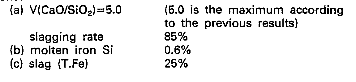
- When the operating conditions of the top and bottom blowing converter (hereinafter referred to as a combined blow refining) were selected as follows, the dephosphorization equilibriums of the combined blow refining and the top blown converter (the relationship between the above equation and the actual result became as shown in Figure 30).
-
- Then, the calculation of the end-point [P] content determined from the phosphorus balance in accordance with the following equation.

- As will be seen from Figure 31, the end-point [P] end-point of 0.006% can be ensured by the [P] input of 0.120% and it is possible to ensure the ingot steel [P] content of 0.012% in consideration of the recovered phosphorus from the slag and the pickup from the alloys. Figure 32 is a graph showing the relationship between the flow rate of bottom-blown gas and the end-point [C] and [P] contents, and Figure 33 is a graph showing the relationship between the flow rate of bottom-blown gas and the end-point [C] content and the T.Fe content.
- An important point of this method is the effect of further blowing the bottom-blown gas alone after the completion of the blow refining (hereafter referred to as a rinse effect) will be explained. Figure 34 is a graph showing the changes in the [P] content before and after the rinse, Figure 35 is a graph showing the temperature drop due to the rinse, and Figure 36 is a graph showing the changes in the slag composition due to the rinse.
- As will be seen from these Figures, the dephosphorization equilibrium after the rinse conforms with the previously mentioned dephosphorization equilibrium equation due to the slag composition (basicity) and the [P] and (P205) contents after the rinse, and there is a condition which promotes the dephosphorization further due to the increased (CaO) despite the decreased (T.Fe) content in the slag composition and the decrease in the slag temperature caused by the rinse.
- This method makes possible the production of low phosphorus steel in the top and bottom blowing converter using the single slag process and this has the effect of reducing the steel-making time considerably as compared with conventional methods.
Claims (8)
Applications Claiming Priority (14)
| Application Number | Priority Date | Filing Date | Title |
|---|---|---|---|
| JP50550/82 | 1982-03-29 | ||
| JP5054682A JPS58167715A (en) | 1982-03-29 | 1982-03-29 | Refractory material for nozzle useful in refining molten metal |
| JP50546/82 | 1982-03-29 | ||
| JP5055182A JPS58167717A (en) | 1982-03-29 | 1982-03-29 | Nozzle for molten metal refining |
| JP50549/82 | 1982-03-29 | ||
| JP5055082A JPS58167710A (en) | 1982-03-29 | 1982-03-29 | Nozzle for molten metal refining |
| JP50547/82 | 1982-03-29 | ||
| JP50545/82 | 1982-03-29 | ||
| JP50548/82 | 1982-03-29 | ||
| JP5054782A JPS58167707A (en) | 1982-03-29 | 1982-03-29 | Method of smelting high-carbon steel by top and bottom-blown converter |
| JP5054982A JPS58167716A (en) | 1982-03-29 | 1982-03-29 | Gas blowing nozzle and its manufacturing method |
| JP50551/82 | 1982-03-29 | ||
| JP5054882A JPS58167708A (en) | 1982-03-29 | 1982-03-29 | Method of controlling molten steel [N] using a top-bottom blowing converter |
| JP5054582A JPS58167706A (en) | 1982-03-29 | 1982-03-29 | Melting method of low P steel using top-down blowing converter |
Publications (3)
| Publication Number | Publication Date |
|---|---|
| EP0105380A1 EP0105380A1 (en) | 1984-04-18 |
| EP0105380A4 EP0105380A4 (en) | 1984-08-10 |
| EP0105380B1 true EP0105380B1 (en) | 1988-05-11 |
Family
ID=27564746
Family Applications (1)
| Application Number | Title | Priority Date | Filing Date |
|---|---|---|---|
| EP83900974A Expired EP0105380B1 (en) | 1982-03-29 | 1983-03-29 | Bottom blowing gas nozzle in molten metal refining furnace and method of melting steel using the same nozzle |
Country Status (4)
| Country | Link |
|---|---|
| US (1) | US4539043A (en) |
| EP (1) | EP0105380B1 (en) |
| AU (1) | AU567023B2 (en) |
| WO (1) | WO1983003427A1 (en) |
Families Citing this family (21)
| Publication number | Priority date | Publication date | Assignee | Title |
|---|---|---|---|---|
| LU85131A1 (en) * | 1983-12-12 | 1985-09-12 | Arbed | GAS-PERMEABLE CONSTRUCTION BODY MADE OF FIRE-RESISTANT MATERIAL |
| DE3523171C1 (en) * | 1985-06-28 | 1986-10-30 | Didier-Werke Ag, 6200 Wiesbaden | Gas purging device |
| DE3664485D1 (en) * | 1985-12-04 | 1989-08-24 | Didier Werke Ag | Gas-flushing installation for melt containers |
| AT384623B (en) * | 1985-12-23 | 1987-12-10 | Tosin Albert | COOLING STONE FOR METALLURGICAL VESSELS |
| US4735400A (en) * | 1986-03-28 | 1988-04-05 | Toshin Steel Co., Ltd. | Plug for a refining apparatus |
| FR2601695B1 (en) * | 1986-03-28 | 1990-12-21 | Toshin Steel Co | CAP FOR REFINING APPARATUS |
| FR2601694B1 (en) * | 1986-03-28 | 1990-12-21 | Toshin Steel Co | CAP FOR REFINING APPARATUS |
| FR2601693B1 (en) * | 1986-03-28 | 1990-12-21 | Toshin Steel Co | CAP FOR REFINING APPARATUS |
| CA1311787C (en) * | 1986-06-24 | 1992-12-22 | Masahisa Tate | Method of bottom blowing operation of a steel making electric furnace |
| US4741515A (en) * | 1986-10-20 | 1988-05-03 | Bethlehem Steel Corporation | Apparatus for introducing gas into a metallurgical vessel |
| US5249778A (en) * | 1992-04-14 | 1993-10-05 | Dolomitwerke Gmbh | Gas stir plug device with visual wear indicator |
| CA2073219C (en) * | 1992-07-06 | 1995-12-19 | Keizo Aramaki | Refractory for gas blowing for molten metal refining vessel |
| DE4411538C1 (en) * | 1994-04-02 | 1995-12-14 | Didier Werke Ag | Method for producing a gas and / or solid-state blowing device for metallurgical vessels, and blowing device produced according to the method |
| RU2129165C1 (en) * | 1997-12-08 | 1999-04-20 | Акционерное общество "Шибер" | Device for bottom blowing of metal |
| RU2186858C2 (en) * | 2000-03-13 | 2002-08-10 | ОАО Челябинский металлургический комбинат "МЕЧЕЛ" | Lance for bottom blowing of metal with gases in ladle and method of lance manufacture |
| SE0001593L (en) * | 2000-05-02 | 2001-10-08 | Sahlin Gjutteknik Ab | A purge plug |
| SE515802C2 (en) * | 2000-05-02 | 2001-10-08 | Sahlin Gjutteknik Ab | A purge plug |
| RU2230796C1 (en) * | 2003-03-06 | 2004-06-20 | Хлопонин Виктор Николаевич | Blow-off component of an aggregate for steel production or its heat finishing |
| ES2578801B1 (en) * | 2016-01-28 | 2017-02-13 | La Farga Lacambra, S.A.U. | GAS FEEDING SYSTEM FOR FOUNDING OVENS AND RELATED GAS FEEDING METHOD |
| CN111763805B (en) * | 2020-09-01 | 2020-12-08 | 北京利尔高温材料股份有限公司 | A kind of breathable brick based on cold isostatic pressing wet bag method and preparation method thereof |
| CN116288136B (en) * | 2023-03-23 | 2023-10-20 | 首钢智新迁安电磁材料有限公司 | Nitriding device and nitriding method for oriented silicon steel |
Citations (2)
| Publication number | Priority date | Publication date | Assignee | Title |
|---|---|---|---|---|
| JPS5837110A (en) * | 1981-08-27 | 1983-03-04 | Nippon Kokan Kk <Nkk> | Refining method of converter |
| JPS5834943U (en) * | 1981-08-27 | 1983-03-07 | 日本鋼管株式会社 | Nozzle for molten metal refining |
Family Cites Families (8)
| Publication number | Priority date | Publication date | Assignee | Title |
|---|---|---|---|---|
| US2855293A (en) * | 1955-03-21 | 1958-10-07 | Air Liquide | Method and apparatus for treating molten metal with oxygen |
| LU53932A1 (en) * | 1962-08-07 | 1967-08-21 | ||
| BE635868A (en) * | 1962-08-07 | |||
| SE392479B (en) * | 1974-03-20 | 1977-03-28 | Asea Ab | FORMA AT METALLURGIC CONVERTERS AND MELTING OVEN |
| GB2041182B (en) * | 1978-12-21 | 1983-01-26 | Kawasaki Steel Co | Method for blowing gas from below into a molten steel in refining vessel |
| JPS57116765U (en) * | 1980-12-29 | 1982-07-20 | ||
| GB2102926B (en) * | 1981-06-03 | 1985-05-15 | Nippon Kokan Kk | Gas blowing nozzle, and production and usage thereof |
| AU541441B2 (en) * | 1981-07-15 | 1985-01-10 | Nippon Steel Corporation | Bottom blowing nozzle embedded in a refractory block |
-
1983
- 1983-03-29 WO PCT/JP1983/000098 patent/WO1983003427A1/en not_active Ceased
- 1983-03-29 AU AU13719/83A patent/AU567023B2/en not_active Ceased
- 1983-03-29 US US06/556,162 patent/US4539043A/en not_active Expired - Fee Related
- 1983-03-29 EP EP83900974A patent/EP0105380B1/en not_active Expired
Patent Citations (2)
| Publication number | Priority date | Publication date | Assignee | Title |
|---|---|---|---|---|
| JPS5837110A (en) * | 1981-08-27 | 1983-03-04 | Nippon Kokan Kk <Nkk> | Refining method of converter |
| JPS5834943U (en) * | 1981-08-27 | 1983-03-07 | 日本鋼管株式会社 | Nozzle for molten metal refining |
Also Published As
| Publication number | Publication date |
|---|---|
| WO1983003427A1 (en) | 1983-03-29 |
| AU567023B2 (en) | 1987-11-05 |
| AU1371983A (en) | 1983-10-24 |
| EP0105380A1 (en) | 1984-04-18 |
| EP0105380A4 (en) | 1984-08-10 |
| US4539043A (en) | 1985-09-03 |
Similar Documents
| Publication | Publication Date | Title |
|---|---|---|
| US4539043A (en) | Bottom-blown gas blowing nozzle | |
| CA1200095A (en) | Gas blowing nozzle, and production and usage thereof | |
| US4210264A (en) | Immersion nozzle for continuous casting of molten steel | |
| GB1599176A (en) | Killed steels for continuous casting | |
| GB2093169A (en) | Metal pouring apparatus and method | |
| US5885473A (en) | Long nozzle for continuous casting | |
| US4192490A (en) | Lance for injecting powdery material into molten metal | |
| US4465514A (en) | Method of producing steel by the LD process | |
| US4815715A (en) | Gas purging assembly for supplying gas to molten metal in a metallurgical vessel | |
| CN216107060U (en) | Single-tube double-hole dip pipe with double circular flow argon pipes | |
| EP0128987B1 (en) | Tuyere and method for blowing gas into molten metal | |
| US5911946A (en) | Snorkel for a degassing vessel | |
| US4420334A (en) | Method for controlling the bottom-blowing gas in top-and-bottom blown converter steel making | |
| CA1297144C (en) | Gas scavenging apparatus for metallurgical vessels | |
| US4477279A (en) | Annular tuyere and method | |
| CA1209807A (en) | Bottom-blown gas blowing nozzle for molten metal refining furnace and steel refining method using the same | |
| GB2081702A (en) | Immersion Nozzle for Continuous Casting of Molten Steel | |
| US4415358A (en) | Method of desulfurizing a ferrous melt | |
| US4676486A (en) | Reaction vessel for smelting iron ore and method | |
| EP0577873B1 (en) | Refractory for gas blowing for molten metal refining vessel | |
| US4421555A (en) | Method of and apparatus for metallurgical treatment of a melt | |
| US4353533A (en) | Bottom tuyeres in an oxygen top-blown converter | |
| KR100336860B1 (en) | Composite blower with low odor nozzle arranged to have excellent stirring power | |
| EP0767021A3 (en) | Ladle cover for vacuum refining process | |
| JPS57158316A (en) | Production of al-containing steel |
Legal Events
| Date | Code | Title | Description |
|---|---|---|---|
| PUAI | Public reference made under article 153(3) epc to a published international application that has entered the european phase |
Free format text: ORIGINAL CODE: 0009012 |
|
| AK | Designated contracting states |
Designated state(s): BE FR GB |
|
| 17P | Request for examination filed |
Effective date: 19840331 |
|
| GRAA | (expected) grant |
Free format text: ORIGINAL CODE: 0009210 |
|
| AK | Designated contracting states |
Kind code of ref document: B1 Designated state(s): BE FR GB |
|
| ET | Fr: translation filed | ||
| PLBE | No opposition filed within time limit |
Free format text: ORIGINAL CODE: 0009261 |
|
| STAA | Information on the status of an ep patent application or granted ep patent |
Free format text: STATUS: NO OPPOSITION FILED WITHIN TIME LIMIT |
|
| 26N | No opposition filed | ||
| PGFP | Annual fee paid to national office [announced via postgrant information from national office to epo] |
Ref country code: FR Payment date: 19950309 Year of fee payment: 13 |
|
| PGFP | Annual fee paid to national office [announced via postgrant information from national office to epo] |
Ref country code: GB Payment date: 19950321 Year of fee payment: 13 |
|
| PGFP | Annual fee paid to national office [announced via postgrant information from national office to epo] |
Ref country code: BE Payment date: 19950510 Year of fee payment: 13 |
|
| PG25 | Lapsed in a contracting state [announced via postgrant information from national office to epo] |
Ref country code: GB Effective date: 19960329 |
|
| PG25 | Lapsed in a contracting state [announced via postgrant information from national office to epo] |
Ref country code: BE Effective date: 19960331 |
|
| BERE | Be: lapsed |
Owner name: NIPPON KOKAN K.K. Effective date: 19960331 |
|
| GBPC | Gb: european patent ceased through non-payment of renewal fee |
Effective date: 19960329 |
|
| PG25 | Lapsed in a contracting state [announced via postgrant information from national office to epo] |
Ref country code: FR Effective date: 19961129 |
|
| REG | Reference to a national code |
Ref country code: FR Ref legal event code: ST |