EP0105274B1 - Improved building block or panel - Google Patents
Improved building block or panel Download PDFInfo
- Publication number
- EP0105274B1 EP0105274B1 EP82903291A EP82903291A EP0105274B1 EP 0105274 B1 EP0105274 B1 EP 0105274B1 EP 82903291 A EP82903291 A EP 82903291A EP 82903291 A EP82903291 A EP 82903291A EP 0105274 B1 EP0105274 B1 EP 0105274B1
- Authority
- EP
- European Patent Office
- Prior art keywords
- panel
- building block
- face
- faces
- edge
- Prior art date
- Legal status (The legal status is an assumption and is not a legal conclusion. Google has not performed a legal analysis and makes no representation as to the accuracy of the status listed.)
- Expired
Links
Images





Classifications
-
- E—FIXED CONSTRUCTIONS
- E04—BUILDING
- E04B—GENERAL BUILDING CONSTRUCTIONS; WALLS, e.g. PARTITIONS; ROOFS; FLOORS; CEILINGS; INSULATION OR OTHER PROTECTION OF BUILDINGS
- E04B2/00—Walls, e.g. partitions, for buildings; Wall construction with regard to insulation; Connections specially adapted to walls
- E04B2/02—Walls, e.g. partitions, for buildings; Wall construction with regard to insulation; Connections specially adapted to walls built-up from layers of building elements
- E04B2/04—Walls having neither cavities between, nor in, the solid elements
- E04B2/12—Walls having neither cavities between, nor in, the solid elements using elements having a general shape differing from that of a parallelepiped
-
- E—FIXED CONSTRUCTIONS
- E04—BUILDING
- E04B—GENERAL BUILDING CONSTRUCTIONS; WALLS, e.g. PARTITIONS; ROOFS; FLOORS; CEILINGS; INSULATION OR OTHER PROTECTION OF BUILDINGS
- E04B2/00—Walls, e.g. partitions, for buildings; Wall construction with regard to insulation; Connections specially adapted to walls
- E04B2/02—Walls, e.g. partitions, for buildings; Wall construction with regard to insulation; Connections specially adapted to walls built-up from layers of building elements
- E04B2002/0202—Details of connections
- E04B2002/0204—Non-undercut connections, e.g. tongue and groove connections
- E04B2002/0208—Non-undercut connections, e.g. tongue and groove connections of trapezoidal shape
-
- E—FIXED CONSTRUCTIONS
- E04—BUILDING
- E04B—GENERAL BUILDING CONSTRUCTIONS; WALLS, e.g. PARTITIONS; ROOFS; FLOORS; CEILINGS; INSULATION OR OTHER PROTECTION OF BUILDINGS
- E04B2/00—Walls, e.g. partitions, for buildings; Wall construction with regard to insulation; Connections specially adapted to walls
- E04B2/02—Walls, e.g. partitions, for buildings; Wall construction with regard to insulation; Connections specially adapted to walls built-up from layers of building elements
- E04B2002/0202—Details of connections
- E04B2002/0204—Non-undercut connections, e.g. tongue and groove connections
- E04B2002/021—Non-undercut connections, e.g. tongue and groove connections of triangular shape
-
- E—FIXED CONSTRUCTIONS
- E04—BUILDING
- E04B—GENERAL BUILDING CONSTRUCTIONS; WALLS, e.g. PARTITIONS; ROOFS; FLOORS; CEILINGS; INSULATION OR OTHER PROTECTION OF BUILDINGS
- E04B2/00—Walls, e.g. partitions, for buildings; Wall construction with regard to insulation; Connections specially adapted to walls
- E04B2/02—Walls, e.g. partitions, for buildings; Wall construction with regard to insulation; Connections specially adapted to walls built-up from layers of building elements
- E04B2002/0202—Details of connections
- E04B2002/0204—Non-undercut connections, e.g. tongue and groove connections
- E04B2002/0213—Non-undercut connections, e.g. tongue and groove connections of round shape
Definitions
- THIS INVENTION relates to an improved building block or panel according to the preamble of claim 1.
- a building block or panel having the shape of a right parallelepiped having two opposed major faces, the remaining faces being edge faces which are formed to interlockingly engage with the edge faces of similar building blocks characterised in that two pairs of adjacent edge faces at opposed corners of the block formed by said edge faces have each pair formed with elongate recesses extending from the respective corner of said block to an intermediate location on each edge face, each edge face also being formed with an elongate projection which is able to be received in the recess of a corresponding block; each recess having one end at said intermediate location and being contoured to define a face which is inclined at an angle of less than 90° between said face and the edge face of the block and wherein the other end of each projecton has a face of a complementary configuration.
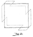
- the embodiment as shown in the drawings is directed to a building block having the shape of a right parallelepiped having two opposed major faces 11 which are substantially square, separated by four edge faces which are rectangular.
- Each edge face is formed with a recess 13 of a V-shaped configuration extending approximately half the length of each face and wherein the recesses of a pair of adjacent edge faces open into each other at the corner.
- the recesses of the respective edge faces also open into each other.
- the remaining portion of each edge face is formed with a projection 15 having a cross-sectional configuration which is complementary to the recess 13 such that it would be fully received in the recess of a corresponding block.
- each edge face 17 so formed is substantially planar, is transversely positioned across the edge face and forms an acute angle of approximately 45° or greater with the base of the recess to overlie the recess.
- the other end 19 of each pair of projections 15 which are adjacent the corners of the block are planar and are formed to define an angle which is complementary to the angle at the junction end 17 of the projection (ie; 45° or less).
- the adjacent other ends 19 of the projections 15 of a pair of adjacent faces are substantially co-planar.
- the recess and elongate projections of the block need not be of equal length.
- the cross-sectional profile of the elongate projections and recesses may be of any desired configuration.
- the recess and elongate projection need not be centrally located on the edge faces of the block and as shown at Figure 6G, the portions of the edge faces to either side of the recess and elongate projection may be contoured.
- the edge face configuration of 6G facilitates the fabrication of curved walls and if desired may be restricted to one or a pair of opposed edge faces of a block.
- the major faces of the block may be contoured and in the cases shown at Figures 7A and 7B, where the major faces are curved about a transverse axis, the recesses and elongate projections of the respective blocks of the respective edge faces may or may not adapt a corresponding curvature.
Landscapes
- Engineering & Computer Science (AREA)
- Architecture (AREA)
- Physics & Mathematics (AREA)
- Electromagnetism (AREA)
- Civil Engineering (AREA)
- Structural Engineering (AREA)
- Finishing Walls (AREA)
- Control Of Position, Course, Altitude, Or Attitude Of Moving Bodies (AREA)
- Toys (AREA)
Description
- THIS INVENTION relates to an improved building block or panel according to the preamble of
claim 1. - There have been numerous attempts to provide building block or panels with interlocking edges which can be assembled without the need for bonding agents to form walls and similar structures. One such interlocking block is described in my Australian Patent No. 274695. Whilst this interlocking block proved to be satisfactory in use, it has now been found that by providing diagonally opposite corners of a rectangular or square block or panel with recesses which extend around the corner and by providing the other pair of diagonally opposite corners with projections, the blocks or panels can be locked together in a manner which gives considerable strength in a wall structure to provide a wall structure which can resist forces applied transversely to the wall. In addition, the block of Patent 274695 required a high degree of precision which was unacceptable to conventional manufacturing practice. Another form of block is disclosed in French patent specification FR-A-1394856. The difficulty created by such blocks however relates to the failure of such blocks to interlock to prevent relative displacement of a pair of blocks in a direction perpendicular to their edge faces.
- According to the present invention we provide a building block or panel having the shape of a right parallelepiped having two opposed major faces, the remaining faces being edge faces which are formed to interlockingly engage with the edge faces of similar building blocks characterised in that two pairs of adjacent edge faces at opposed corners of the block formed by said edge faces have each pair formed with elongate recesses extending from the respective corner of said block to an intermediate location on each edge face, each edge face also being formed with an elongate projection which is able to be received in the recess of a corresponding block; each recess having one end at said intermediate location and being contoured to define a face which is inclined at an angle of less than 90° between said face and the edge face of the block and wherein the other end of each projecton has a face of a complementary configuration.
- The invention will be better understood by reference to the following description of one specific embodiment of the invention shown in the accompanying drawings wherein:-
- Figure 1 is a side elevation of one block;
- Figure 2 is an inverted plan view;
- Figure 3 is a section on line 3-3 of Figure 1;
- Figure 4 is a perspective view;
- Figures 5A & 5B illustrate two further alternatives of blocks according to the invention;
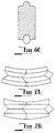
- Figures 6 illustrate alternative cross-sectional configurations of the groove and elongate projection of blocks according to the invention; and
- Figures 7A & 7B illustrate two alternative profiles of blocks according to the invention.
- The embodiment as shown in the drawings is directed to a building block having the shape of a right parallelepiped having two opposed
major faces 11 which are substantially square, separated by four edge faces which are rectangular. Each edge face is formed with arecess 13 of a V-shaped configuration extending approximately half the length of each face and wherein the recesses of a pair of adjacent edge faces open into each other at the corner. At the diagonally opposite corner the recesses of the respective edge faces also open into each other. The remaining portion of each edge face is formed with aprojection 15 having a cross-sectional configuration which is complementary to therecess 13 such that it would be fully received in the recess of a corresponding block. At the junction of therecess 13 with the projection at each edge face theend face 17 so formed, is substantially planar, is transversely positioned across the edge face and forms an acute angle of approximately 45° or greater with the base of the recess to overlie the recess. The other end 19 of each pair ofprojections 15 which are adjacent the corners of the block are planar and are formed to define an angle which is complementary to the angle at thejunction end 17 of the projection (ie; 45° or less). The adjacent other ends 19 of theprojections 15 of a pair of adjacent faces are substantially co-planar. - On location of the blocks in position the projections on one block are received in the recesses of the adjacent blocks and due to the complementary configurations of the opposite ends of the projections, the blocks when in position lock into each other and thus the blocks of each course will be locked into engagement with each other and each course of blocks will be locked together.
- As shown at Figures 5A and 5B, the recess and elongate projections of the block need not be of equal length. In addition, as shown at Figures 6A to 6B, the cross-sectional profile of the elongate projections and recesses may be of any desired configuration. In particular as shown at Figure 6F, the recess and elongate projection need not be centrally located on the edge faces of the block and as shown at Figure 6G, the portions of the edge faces to either side of the recess and elongate projection may be contoured. The edge face configuration of 6G facilitates the fabrication of curved walls and if desired may be restricted to one or a pair of opposed edge faces of a block. The major faces of the block may be contoured and in the cases shown at Figures 7A and 7B, where the major faces are curved about a transverse axis, the recesses and elongate projections of the respective blocks of the respective edge faces may or may not adapt a corresponding curvature.
- It should be appreciated that the scope of the present invention need not be limited to the particular scope of the embodiment described above and in particular to the particular cross-sectional configuration of the recesses or projections or of the interlocking end faces referred to in the specification. In addition, the invention includes within its scope panels as stated in the claims.
Claims (13)
Applications Claiming Priority (2)
| Application Number | Priority Date | Filing Date | Title |
|---|---|---|---|
| AUPF153381 | 1981-11-12 | ||
| AU1533/81 | 1981-11-12 |
Publications (3)
| Publication Number | Publication Date |
|---|---|
| EP0105274A1 EP0105274A1 (en) | 1984-04-18 |
| EP0105274A4 EP0105274A4 (en) | 1985-06-26 |
| EP0105274B1 true EP0105274B1 (en) | 1989-03-01 |
Family
ID=3769264
Family Applications (1)
| Application Number | Title | Priority Date | Filing Date |
|---|---|---|---|
| EP82903291A Expired EP0105274B1 (en) | 1981-11-12 | 1982-11-11 | Improved building block or panel |
Country Status (9)
| Country | Link |
|---|---|
| US (1) | US4593513A (en) |
| EP (1) | EP0105274B1 (en) |
| BR (1) | BR8208077A (en) |
| CA (1) | CA1185449A (en) |
| DE (1) | DE3279477D1 (en) |
| GB (1) | GB2131062B (en) |
| IT (1) | IT1153018B (en) |
| NO (1) | NO832520L (en) |
| WO (1) | WO1983001803A1 (en) |
Cited By (1)
| Publication number | Priority date | Publication date | Assignee | Title |
|---|---|---|---|---|
| DE9420670U1 (en) * | 1994-12-24 | 1996-04-25 | Bramsiepe, Robert, 45257 Essen | Building block |
Families Citing this family (33)
| Publication number | Priority date | Publication date | Assignee | Title |
|---|---|---|---|---|
| NZ212519A (en) * | 1984-06-25 | 1988-11-29 | Trio Dev Pty Ltd | Building components with curved interlocking pieces for self supporting structure |
| FR2711165B1 (en) * | 1993-10-13 | 1995-12-15 | Paul Soulas | Built-in element for anti-crack walls. |
| AU2684995A (en) * | 1994-06-09 | 1996-01-04 | Chester Oliver Bishop | Building components |
| US5930964A (en) * | 1998-02-04 | 1999-08-03 | Boehning; John W. | Composite lightweight building element and methods of making and using same |
| CN100402750C (en) * | 1998-08-17 | 2008-07-16 | 罗尔夫·沙伊威勒 | Paving stone |
| US6253518B1 (en) * | 1998-12-24 | 2001-07-03 | Tony J. Azar | Mortarless brick |
| USD430680S (en) * | 1999-01-15 | 2000-09-05 | Handy-Stone Corporation | Concrete block |
| AU3214600A (en) | 1999-01-22 | 2000-08-07 | Glenn H. Bostock | Wall paneling assembly and system |
| AUPQ285499A0 (en) * | 1999-09-15 | 1999-10-07 | Henderik Corporaal | Building block or panel |
| DE20115271U1 (en) * | 2001-09-15 | 2003-02-06 | SP-Beton GmbH & Co. KG, 21481 Lauenburg | Flooring element to form a floor channel |
| CA2359923C (en) * | 2001-10-25 | 2004-12-14 | Tony Azar | Building blocks |
| MXPA06012165A (en) * | 2004-04-29 | 2007-01-17 | Keystone Retaining Wall System | Veneers for walls, retaining walls and the like. |
| US20060065493A1 (en) * | 2004-09-30 | 2006-03-30 | Bostock Glenn H | Hand railing with mounting for receiving panels |
| US8667752B2 (en) | 2010-06-25 | 2014-03-11 | Robert Pollack | Interlocking construction systems and methods |
| US20070181380A1 (en) * | 2006-01-20 | 2007-08-09 | Bostock Glenn A | Panel assembly with trim plates |
| GB2445182B (en) * | 2006-12-23 | 2011-03-23 | James Alan Thompson | Assembly for dissipating wave energy through diffraction |
| US8113840B2 (en) * | 2007-01-22 | 2012-02-14 | SnapHouse, LLC | Method and apparatus for an architectural design aid system |
| AU2008265549A1 (en) * | 2007-06-21 | 2008-12-24 | Keystone Retaining Wall Systems, Inc. | Veneers for walls, retaining walls, retaining wall blocks, and the like |
| US20090151281A1 (en) * | 2007-11-20 | 2009-06-18 | Keystone Retaining Wall Systems, Inc. | Method of constructing a wall or fence with panels |
| EP2319048B1 (en) | 2008-08-22 | 2015-08-12 | Veritas Medical Solutions, LLC | Masonry block with continuously curved surfaces |
| CA3106531A1 (en) * | 2009-09-29 | 2011-04-07 | Keystone Retaining Wall Systems, Inc. | Wall blocks, veneer panels for wall blocks and method of constructing walls |
| US9072980B2 (en) * | 2010-07-16 | 2015-07-07 | Martijn Van Tilburg | Modular and stackable dollhouse |
| WO2012040789A1 (en) * | 2010-10-01 | 2012-04-05 | University Of Western Australia | Construction block |
| DE102011118113A1 (en) * | 2011-08-31 | 2013-02-28 | Drössler GmbH Umwelttechnik | concrete structure |
| US8601758B2 (en) * | 2011-09-08 | 2013-12-10 | Samobi Industries, Llc | Interlocking construction blocks |
| FI20150172A (en) * | 2015-06-11 | 2016-12-12 | Pär Åke Silén | Prefabricated component system |
| CA3031655C (en) | 2015-07-24 | 2020-06-30 | Keystone Retaining Wall Systems Llc | Connection surface for a structural unit and method of making same |
| US9809971B2 (en) * | 2016-02-25 | 2017-11-07 | Spherical Block LLC | Architectural building block |
| CA3030708A1 (en) | 2016-07-21 | 2018-01-25 | Keystone Retaining Wall Systems Llc | Veneer connectors, wall blocks, veneer panels for wall blocks, and walls |
| TWI678447B (en) * | 2018-05-15 | 2019-12-01 | 淨斯人間志業股份有限公司 | Linkage brick assembly, assembly method thereof, unit assembled brick and assembly method thereof |
| BR202018011162U2 (en) * | 2018-05-30 | 2019-12-03 | Cesar Augusto Marcos | snap block arrangement |
| US11326343B2 (en) | 2020-07-02 | 2022-05-10 | Anchor Wall Systems, Inc. | Modular concrete building block and methods |
| GB2610405A (en) * | 2021-09-02 | 2023-03-08 | Lockett Daniel | A construction module and a method of forming a construction module |
Family Cites Families (13)
| Publication number | Priority date | Publication date | Assignee | Title |
|---|---|---|---|---|
| CA489803A (en) * | 1953-01-20 | T. Baldanza Nicholas | Building blocks | |
| US1430392A (en) * | 1920-11-01 | 1922-09-26 | Richardson Co | Colored fibrous composition and process of manufacture thereof |
| GB254416A (en) * | 1925-04-08 | 1926-07-08 | Wright Rubber Products Company | Improvements in or relating to paving or covering blocks and pavements made therewith |
| US1969729A (en) * | 1930-11-18 | 1934-08-14 | Damianik Joao | Formation or production of blocks |
| US2189218A (en) * | 1937-12-06 | 1940-02-06 | Celotex Corp | Tiling |
| US2882714A (en) * | 1955-10-14 | 1959-04-21 | Phillips Petroleum Co | Laminated interlocking block |
| FR1394856A (en) * | 1964-02-24 | 1965-04-09 | Floating slab | |
| US3557501A (en) * | 1966-03-28 | 1971-01-26 | Arpad Kolozsvary | Folded plate structures and components therefor |
| FR90076E (en) * | 1966-05-24 | 1967-10-06 | Dev Ind Proclem Soc Et | paving elements ensuring load distribution |
| US3672110A (en) * | 1971-02-16 | 1972-06-27 | Christer Nordstrom | Building block |
| GB1479050A (en) * | 1974-12-18 | 1977-07-06 | Golder Ass Ltd | Building block |
| FR2509344A1 (en) * | 1981-07-10 | 1983-01-14 | Bride Michel | HYPER-PRESSED AND STABILIZED EARTH BLOCK FOR CONSTRUCTION |
| US4429506A (en) * | 1982-04-08 | 1984-02-07 | Henderson Eugene R | Interlocking building block |
-
1982
- 1982-11-11 BR BR8208077A patent/BR8208077A/en unknown
- 1982-11-11 WO PCT/AU1982/000184 patent/WO1983001803A1/en not_active Ceased
- 1982-11-11 GB GB08330795A patent/GB2131062B/en not_active Expired
- 1982-11-11 DE DE8282903291T patent/DE3279477D1/en not_active Expired
- 1982-11-11 US US06/513,963 patent/US4593513A/en not_active Expired - Lifetime
- 1982-11-11 EP EP82903291A patent/EP0105274B1/en not_active Expired
- 1982-11-12 IT IT24227/82A patent/IT1153018B/en active
- 1982-11-12 CA CA000415453A patent/CA1185449A/en not_active Expired
-
1983
- 1983-07-11 NO NO832520A patent/NO832520L/en unknown
Cited By (1)
| Publication number | Priority date | Publication date | Assignee | Title |
|---|---|---|---|---|
| DE9420670U1 (en) * | 1994-12-24 | 1996-04-25 | Bramsiepe, Robert, 45257 Essen | Building block |
Also Published As
| Publication number | Publication date |
|---|---|
| US4593513A (en) | 1986-06-10 |
| WO1983001803A1 (en) | 1983-05-26 |
| DE3279477D1 (en) | 1989-04-06 |
| EP0105274A1 (en) | 1984-04-18 |
| CA1185449A (en) | 1985-04-16 |
| GB2131062A (en) | 1984-06-13 |
| IT8224227A1 (en) | 1984-05-12 |
| GB2131062B (en) | 1985-06-26 |
| BR8208077A (en) | 1984-04-17 |
| GB8330795D0 (en) | 1983-12-29 |
| IT8224227A0 (en) | 1982-11-12 |
| EP0105274A4 (en) | 1985-06-26 |
| IT1153018B (en) | 1987-01-14 |
| NO832520L (en) | 1983-07-11 |
Similar Documents
| Publication | Publication Date | Title |
|---|---|---|
| US4593513A (en) | Building block or panel | |
| US5428933A (en) | Insulating construction panel or block | |
| AU756679B2 (en) | Dry stackable block structures | |
| US4671039A (en) | Block | |
| US5457926A (en) | Interlocking block | |
| US5482491A (en) | Block assembly | |
| US3339954A (en) | Means for releasable connection of building elements | |
| US4262463A (en) | Pressed blocks for interlocked assembly | |
| JPH0343417B2 (en) | ||
| US3992839A (en) | Snap-on paneling | |
| US4633630A (en) | Structural blocks and structural system utilizing same | |
| GB2185276A (en) | Building blocks | |
| US6679022B1 (en) | Building block or panel | |
| CA1184731A (en) | Framework block or brick consisting of modular elements of formed sheet steel or aluminium and comprising jointing means | |
| EP0803016B1 (en) | Insulating construction member or block. | |
| EP0589326B1 (en) | Laminar staple for angularly joining profiled strips | |
| EP0022100B1 (en) | Elongated building structure | |
| US5121575A (en) | Spacers for block constructions to maintain the alignment thereof | |
| AU9057582A (en) | Improved building block or panel | |
| US5353561A (en) | Area separation wall and stud therefor | |
| US4626124A (en) | Structural corner joints | |
| WO1998036136A1 (en) | A building element | |
| WO1995018330A1 (en) | A construction kit | |
| CA1272864A (en) | Structural corner joints | |
| CA2173649A1 (en) | Construction block for building a retaining wall |
Legal Events
| Date | Code | Title | Description |
|---|---|---|---|
| PUAI | Public reference made under article 153(3) epc to a published international application that has entered the european phase |
Free format text: ORIGINAL CODE: 0009012 |
|
| 17P | Request for examination filed |
Effective date: 19831202 |
|
| AK | Designated contracting states |
Designated state(s): DE FR NL SE |
|
| 17Q | First examination report despatched |
Effective date: 19870227 |
|
| RAP1 | Party data changed (applicant data changed or rights of an application transferred) |
Owner name: STRATLOCK LTD. |
|
| GRAA | (expected) grant |
Free format text: ORIGINAL CODE: 0009210 |
|
| RIN1 | Information on inventor provided before grant (corrected) |
Inventor name: STRATTON, FRANK |
|
| AK | Designated contracting states |
Kind code of ref document: B1 Designated state(s): DE FR NL SE |
|
| REF | Corresponds to: |
Ref document number: 3279477 Country of ref document: DE Date of ref document: 19890406 |
|
| ET | Fr: translation filed | ||
| PGFP | Annual fee paid to national office [announced via postgrant information from national office to epo] |
Ref country code: FR Payment date: 19891109 Year of fee payment: 8 |
|
| PGFP | Annual fee paid to national office [announced via postgrant information from national office to epo] |
Ref country code: SE Payment date: 19891121 Year of fee payment: 8 |
|
| PGFP | Annual fee paid to national office [announced via postgrant information from national office to epo] |
Ref country code: NL Payment date: 19891130 Year of fee payment: 8 |
|
| PGFP | Annual fee paid to national office [announced via postgrant information from national office to epo] |
Ref country code: DE Payment date: 19891205 Year of fee payment: 8 |
|
| PLBE | No opposition filed within time limit |
Free format text: ORIGINAL CODE: 0009261 |
|
| STAA | Information on the status of an ep patent application or granted ep patent |
Free format text: STATUS: NO OPPOSITION FILED WITHIN TIME LIMIT |
|
| 26N | No opposition filed | ||
| PG25 | Lapsed in a contracting state [announced via postgrant information from national office to epo] |
Ref country code: SE Effective date: 19901112 |
|
| PG25 | Lapsed in a contracting state [announced via postgrant information from national office to epo] |
Ref country code: NL Effective date: 19910601 |
|
| NLV4 | Nl: lapsed or anulled due to non-payment of the annual fee | ||
| PG25 | Lapsed in a contracting state [announced via postgrant information from national office to epo] |
Ref country code: FR Effective date: 19910731 |
|
| PG25 | Lapsed in a contracting state [announced via postgrant information from national office to epo] |
Ref country code: DE Effective date: 19910801 |
|
| REG | Reference to a national code |
Ref country code: FR Ref legal event code: ST |
|
| EUG | Se: european patent has lapsed |
Ref document number: 82903291.1 Effective date: 19910705 |