EP0104843A2 - Dispositif transducteur - Google Patents
Dispositif transducteur Download PDFInfo
- Publication number
- EP0104843A2 EP0104843A2 EP83305421A EP83305421A EP0104843A2 EP 0104843 A2 EP0104843 A2 EP 0104843A2 EP 83305421 A EP83305421 A EP 83305421A EP 83305421 A EP83305421 A EP 83305421A EP 0104843 A2 EP0104843 A2 EP 0104843A2
- Authority
- EP
- European Patent Office
- Prior art keywords
- phase
- signals
- transducer
- signal
- millimeters
- Prior art date
- Legal status (The legal status is an assumption and is not a legal conclusion. Google has not performed a legal analysis and makes no representation as to the accuracy of the status listed.)
- Withdrawn
Links
Images


Classifications
-
- G—PHYSICS
- G01—MEASURING; TESTING
- G01S—RADIO DIRECTION-FINDING; RADIO NAVIGATION; DETERMINING DISTANCE OR VELOCITY BY USE OF RADIO WAVES; LOCATING OR PRESENCE-DETECTING BY USE OF THE REFLECTION OR RERADIATION OF RADIO WAVES; ANALOGOUS ARRANGEMENTS USING OTHER WAVES
- G01S15/00—Systems using the reflection or reradiation of acoustic waves, e.g. sonar systems
- G01S15/88—Sonar systems specially adapted for specific applications
- G01S15/89—Sonar systems specially adapted for specific applications for mapping or imaging
- G01S15/8906—Short-range imaging systems; Acoustic microscope systems using pulse-echo techniques
- G01S15/8909—Short-range imaging systems; Acoustic microscope systems using pulse-echo techniques using a static transducer configuration
- G01S15/8915—Short-range imaging systems; Acoustic microscope systems using pulse-echo techniques using a static transducer configuration using a transducer array
- G01S15/8922—Short-range imaging systems; Acoustic microscope systems using pulse-echo techniques using a static transducer configuration using a transducer array the array being concentric or annular
-
- A—HUMAN NECESSITIES
- A61—MEDICAL OR VETERINARY SCIENCE; HYGIENE
- A61B—DIAGNOSIS; SURGERY; IDENTIFICATION
- A61B8/00—Diagnosis using ultrasonic, sonic or infrasonic waves
- A61B8/44—Constructional features of the ultrasonic, sonic or infrasonic diagnostic device
- A61B8/4483—Constructional features of the ultrasonic, sonic or infrasonic diagnostic device characterised by features of the ultrasound transducer
-
- G—PHYSICS
- G01—MEASURING; TESTING
- G01S—RADIO DIRECTION-FINDING; RADIO NAVIGATION; DETERMINING DISTANCE OR VELOCITY BY USE OF RADIO WAVES; LOCATING OR PRESENCE-DETECTING BY USE OF THE REFLECTION OR RERADIATION OF RADIO WAVES; ANALOGOUS ARRANGEMENTS USING OTHER WAVES
- G01S7/00—Details of systems according to groups G01S13/00, G01S15/00, G01S17/00
- G01S7/52—Details of systems according to groups G01S13/00, G01S15/00, G01S17/00 of systems according to group G01S15/00
- G01S7/52017—Details of systems according to groups G01S13/00, G01S15/00, G01S17/00 of systems according to group G01S15/00 particularly adapted to short-range imaging
- G01S7/52046—Techniques for image enhancement involving transmitter or receiver
-
- G—PHYSICS
- G10—MUSICAL INSTRUMENTS; ACOUSTICS
- G10K—SOUND-PRODUCING DEVICES; METHODS OR DEVICES FOR PROTECTING AGAINST, OR FOR DAMPING, NOISE OR OTHER ACOUSTIC WAVES IN GENERAL; ACOUSTICS NOT OTHERWISE PROVIDED FOR
- G10K11/00—Methods or devices for transmitting, conducting or directing sound in general; Methods or devices for protecting against, or for damping, noise or other acoustic waves in general
- G10K11/18—Methods or devices for transmitting, conducting or directing sound
- G10K11/26—Sound-focusing or directing, e.g. scanning
- G10K11/34—Sound-focusing or directing, e.g. scanning using electrical steering of transducer arrays, e.g. beam steering
- G10K11/341—Circuits therefor
- G10K11/346—Circuits therefor using phase variation
Definitions
- This invention is in the field of transducer devices and particularly ultrasonic transducer devices which are used in medical practice for providing an image output of various internal structures such as the heart.
- Systems for performing this function may be found in, for example, U.S. patents 4,149,420 and 4,234,937.
- ultrasonic energy is transmitted into the body by a transducer which, for example, may be pivotly mounted such as is shown in U.S. patent 4,316,271. Echos from parts of the body are reflected to the transducer and then converted into electrical signals for use in the imaging systems.
- the ultrasonic transducer may comprise a piston like element which alternately acts as a transmitter and a receiver producing a pulse of ultrasonic energy and then waiting for the return echo to produce an electrical signal, or maybe an array of elements (see patent 3,936,791) which is capable of producing a focused beam of ultrasonic energy.
- a useful alternative configuration for an array of transducers, particularly in medical field is for the elements to be annularly arranged as concentric rings about a central portion like that shown in U.S. patent 4,241,611.
- Delay lines of this sort are shown, for example, in the above referred to U.S. patent 3,936,791.
- the amount of delay should be altered for each specific distance to the object so that the summed signals remain in phase throughout the entire range of the transducer.
- electrically alterable delay lines are difficult and expensive to manufacture and accordingly in practice the delay lines normally have tabs which are switched at appropriate times after a transmit pulse has been sent to provide for several "zones" of delay.
- a transducer device comprising a plurality of transducer elements each producing on receipt of a signal from a remote object an electrical signal varying on both sides of a reference potential, the electrical signals being relatively phased according to the distances of the elements from the object and being such as to interfere with one another at at least one predetermined distance of the device from the object, characterised by converting means responding to each electrical signal to convert it into two resultant signals one in-phase and the other out-of-phase with the electrical signal, range sensing means sensing the distance of the device from the object and producing an output signal when the device is at said one predetermined distance, and switch means receiving the resultant signals and output signal and operable to pass said in-phase signals for summation, and upon receipt of said output signal, to pass for summation with said in-phase signals at least one of the out-of-phase signals while blocking the corresponding in-phase signal whereby to increase the value of the summed signals.
- an ultrasonic transducer 10 is shown consisting of four concentrically arranged transducing elements 12, 14, 16 and 18. While in the preferred embodiment, it will be presumed that a concentric annular array of four elements is being utilized, it should be understood that the present invention would apply equally well to a linear array or to an array containing fewer or more than four elements or, as a matter of fact, to a single ultrasonic piston having a plurality of pick-off points.
- the preferred arrangement of an annular array is such that the transducing elements 12, 14, 16 and 18 all have the same area and accordingly their widths would have to decrease from the center.
- the transducer 10 operates to produce a pulse of sonic energy which travels to the right in Figure 1 where it will be reflected from a remote object such as is shown as point 20 along axis 22 of the transducer 10. It should be understood that the energy transmitted by transducer 10 may be a plane wave or may be focused as discussed, for example, in the above referred to patents 3,936,791 and 4,241,611.
- all of the elements 12 to 18 may operate together to produce the ultrasonic pulse and then change modes so as to receive the reflected energy or, one of the elements such as the central element 18 could be used to transmit the energy while the elements 12, 14 and 16 receive the pulse echo or, the transmission of the energy could be from another transducing element entirely with the reflected energy being received by elements 12 to 18.
- x (a 2- d 2 ) / 2 d . If it is further assumed that the frequency of the ultrasonic energy is 3.5 MHz and that the speed of sound in a body is 1540 meters per second, then the wavelength of the ultrasonic energy will be 0.44 millimeters.
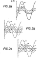
- FIGURE 2a The additive and subtractive effects of the various ultrasonic signals received by transducing elements 12, 14, 16, and 18 can be seen by an examination of FIGURES 2a through 2f.
- four curves 40, 42, 44, and 46 are shown as sine waves which are slightly displaced one from another and may represent the signals being received by transducing elements 12, 14, 16, and 18 respectively in FIGURE 1.
- the situation is such as would occur if the object were quite remote from the transducer at say, 150 millimeters.
- the value of "d" in FIGURE 1 is fairly small and accordingly the distance between the four waves is likewise very small.
- a dashed curve 48 is shown which represents a summation of the curves 40, 42, 44, and 46 although not in scale for convenience.
- a second curve 50 is shown co-extensive with dash-line curve 48 and represents the relative magnitude of the summed output of the transducer elements.12, 14, 16, and 18 of FIGURE 1 when the present device is employed as will be further explained.
- FIGURE 2b the curves 40, 42, 44, and 46 are shown when an object is located at a distance of about 80 millimeters from the transducer head. It is seen now that the distance between the various curves 40-46 has increased somewhat over what was the case in FIGURE 2a and, as a result, the summation curve shown by dash-line 48 is decreased in magnitude since the curves are not as well additive as they were in FIGURE 2a. It will be noted that the curve 50 showing the relative magnitude when the present device is employed is greater than the curve 48.
- FIGURE 2c the situation is represented where the object is located at about 70 millimeters from the transducer and it can be seen that curves 40, 42, 44, and 46 are again further apart than they were in FIGURES 2a and 2b. Likewise the summation curve 48 has further decreased and that the relative curve 50 representing the situation with the use of the present device is significantly larger than curve 48.
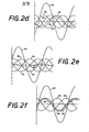
- FIGURE 2d shows the situation when the object is located at approximately 60 millimeters from the transducer and the curves 42, 44, 46, and 48 are considerably out of phase.
- the magnitude of the summation curve 48 has now decreased below the level of the individual curves while the relative curve 50 representing the use of the present device is about twice as large as curve 48.
- FIGURE 2e the situation is represented when the object is at approximately 50 millimeters from the transducer and it is seen that the individual curves 42, 44, and 46 are almost totally out of phase with one another so that the effect is subtractive rather additive.
- curve 48 representing the total of the curves is now only slightly above and below the zero level. It will be recalled that a first null or zero signal occurs when an object is located at 47.79 millimeters from the transducer in the mathematical analysis above. It should also be noted that the curve 50 representing the relative magnitude of the signal when the present device is employed is several time larger than that of the signal represented by curve 48.
- FIGURE 2f shows the situation at a distance of 40 millimeters from the transducer head and it can be seen that curves 40 and 46 are coming close together and are almost in phase while curves 42 and 44 remain somewhat out of phase with respect to the other two.
- the summation curve 48 is now larger than was the case in FIGURE 2e although it is in the opposite sense.
- the signal would have passed from possitive through zero to negative in going from FIGURE 2e to FIGURE 2f.
- the output signals are normally rectified so that the end signal is always possitive.
- the curve 50 representing the signal utilizing the present device is significantly larger than the summation curve 48.
- a curve 56 is shown representing the summation output of an uncompensated transducer with objects at various distances from the transducer head. It is seen that zero cross-overs occur at points represented by reference numerals 58, 60, 62, 64, and 66.
- Point 58 is located at a distance approximately 8.50 millimeters from the transducer head; point 60 is located at a distance approximately 11.12 millimeters from the transducer head; point 62 is located a distance approximately 15.34 millimeters from the transducer head; point 64 is located a distance approximately 23.57 millimeters from the transducer head; and point 66 is located a distance approximately 47.79 millimeters from the transducer head.
- Curve 56 can be drawn by looking at the placement of the individual curves 40, 42, 44,"and 46 such as shown in FIGURES 2a to 2f for all positions of the remote object from a distance starting at about 8 millimeters on up to a distance up to of about 150 millimeters. As mentioned above, those portions of the curve which extend below the zero line in FIGURE 3 would, in actual practice, be rectified so that they were above the zero axis and that all resultant signals would be positive. It is seen from FIGURE 3 that there are several locations along the axis of the transducer where reflections will cancel each other out and thus the transducer will produce no output signal.
- the present device utilizes a technique whereby the outputs of the various transducing elements 12, 14, 16, and 18 in FIGURE 1 are subject to phase reversal at predetermined times representing predetermined distances for a reflecting object so that curves which might otherwise tend to cancel one another become additive.
- transducer element 12 is shown connected by conductor 70 to a differential amplifier 72 having its other input connected to signal ground as at 74.
- Differential amplifier 72 has a first output 76 which will have a signal in phase with the signal on line 70 and a second output 78 which will have a signal 180 degrees out of phase with the signal on line 70.
- transducer element 14 is shown connected by a conductor 80 to a second differential amplifier 82 having its other input connected to signal ground as at 84.
- the in-phase output of differential amplifier 82 is shown on a line 86 and the out-of-phase output of differential amplifier 82 is shown on line 88.
- transducer element 16 is shown connected by a conductor 90 to a third differential amplifier 92 having its other input connected to ground as at 94.
- the in-phase output of differential amplifier 92 is shown on a line 96 while the out-of-phase output of differential amplifier 92 is shown on an output line 98.
- the central transducing element 18 is shown connected by a conductor 100 to a fourth differential amplifier 102 having its other input connected to signal ground as at 104.
- the in-phase output of differential amplifier 102 is shown on a line 106 and the out-of-phase signal from differential amplifier 102 is shown on a line 108.
- Line 76 is connected to a switch 110, line 78 is connected to a switch 112, line 86 is connected to a switch 114, line 88 is connected to a switch 116, line 96 is connected to a switch 118, line 98 is connected to a switch 120, line 106 is connected to a switch 122, and line 108 is connected to a switch 124.
- the output of switches 110-124 are shown connected by lines 130, 132, 134, 136, 138, 140, 142, and 144 respectively to a summation device 146 having a summed output shown as an arrow 148.
- Switches 110-124 are turned off and on by a timer and logic circuit shown as box 150 having an output to switch 110 on a line 152, to switch 112 by line 154, to switch 114 by a line 156, to switch 116, by a line 158, to a switch 118 by a line 160, to switch 120 by a line 162 to switch 122 by a line 164 and to switch 124 by a line 166. While switches 110 and 112,114 and 116, 116 and 120 and 122 and 124 have been shown as separate switches, each pair may comprise a single pole double throw switch with its switch arm connected to summation device 146 and its two contacts connected to the two outputs for its corresponding amplifier 72, 82, 92, and 102 respectively. The outputs from the logic and timer circuit would then operate the switch arms from one contact to another at the required times.
- the timer and logic circuit 150 may comprise a standard ultrasonic pulse generator which transmits a pulse to the elements 12-18 over a line 167 and simultaneously starts a timer which is preset to produce signals to switches 110-124 at predetermined times representing predetermined distances for the sonic pulses from elements to objects in the body under examination.
- a timer which is preset to produce signals to switches 110-124 at predetermined times representing predetermined distances for the sonic pulses from elements to objects in the body under examination.
- the timer will be set to turn the switches 110-124 on and off at appropriate object distances.
- the timer and logic circuit 150 would operate to cause switches 110, 114, 118, and 122 to be on and switches 112, 116, 120, and 124 to be off, and thereby permit only the in-phase components of the signals from differential amplifiers 72, 82, 92, and 102 to be presented to the summation circuit 146.
- the output 148 in FIGURE 1 will therefore be approximately what it would be without the present device as is seen by curve 50 in FIGURE 2a.
- a first portion of curve 168 extends from the far right to about 85 millimeters in FIGURE 3.
- This section 169 of curve 168 is shown with four plus signs "++++" indicating that in this portion of the curve the in-phase components of the outputs of transducers 12, 14, 16, and 18 of FIGURE 1 are passed to the summation circuitry 146. It is also seen that portion 169 of curve 168 is the same as the far right hand portion of curve 56 representing the situation which occurs without the present device.
- This portion of curve 168 is shown in FIGURE 3 as portion 170 and the condition of the transducer elements is shown as "+++-" indicating that switches 122, 118, and 114 are on thereby passing the in-phase components from transducer elements 18, 16, and 14 but the timer and logic circuit 150 has turned switch 110 off and now has turned switch 112 on thereby passing the out-of-phase component of the signal from transducer element 12.
- FIGURE 2b where the curve 50 is somewhat higher than the curve 48 and can be seen in FIGURE 3 where line segment 170 becomes progressively larger than its counterpart on curve 56 for distances from about 85 millimeters to about 60 millimeters.
- phase reverse the outputs from transducer elements 12, 14, and 16 as is shown in FIGURE 3 by the portion of curve 168 having reference numeral 174 and the indication "+---". It is seen in this area 168 that the transducers 12, 14, and 16 are phase reversed thus producing an output considerably higher than the output represented by the counterpart on line 56.
- This phase reversal is performed by the timer and logic circuit 150 turning switches 112, 116, and 120 on, switches 110, 114, and 118 off and leaving switch 124 on thereby passing phased reversed signals along lines 132, 136, and 140 but in-phase signals on line 142 to summation circuit 146.
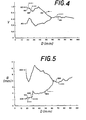
- FIGURE 3 The values shown in FIGURE 3 were obtained from a theoretical analysis of the theoretical wave shapes and phasing shown in FIGURES 2a-2f. In actual measurements taken from an annular non-focused transducer operating at 3.5 MHz, the graph of FIGURE 4 was obtained.
- a curve 180 represents the variation of output without the present device and a curve 182 represents the variation of output utilizing the present device.
- a curve 182 represents the variation of output utilizing the present device.
- FIGURE 4 From a distance of about 95 millimeters to about 60 millimeters from the transducer, there was no appreciable advantage in switching the phasing of any of the elements. This is seen in FIGURE 4 as the portion 184 having "++++" phasing. From about 60 millimeters to about 30 millimeters in a portion of the curve identified as 186, curve 182 increases dramatically from curve 80.
- the present device also operates to provide a signal with a much narrower beam width than was previously possible.
- Figure 5 shows a graph of the beam width (B) versus the distance 'D' from the transducer for the same transducing elements and substantially the same phasings as was used in connection with Figure 4.
- the upper curve identified by reference numeral 200 in Figure 5 represents the beam width variations when the present device is not used while the lower curve 202 represents the beam width variation when the present device is employed. It will be noted that from about 65 millimeters on out to the right in Figure 5 in a portion of the curve identified by reference numeral 204 the phasing was "++++" as was in the case of Figure 4 although in Figure 4 the "++++" started at about 60 millimeters.
- the phasing is "+-+-" as it was in Figure 4 and again the beam width is significantly narrower than it would have been if the present device were not employed.
- the beam width with the present device is much narrower than a transducer beam width without the present device throughout the range where the present device is employed.
- Expdrimentation in measuring the amplitude and beam width from an actual transducer at various distances therefrom will enable one skilled in the art to determine the best phase relationships and switching points to use.
Landscapes
- Engineering & Computer Science (AREA)
- Physics & Mathematics (AREA)
- Remote Sensing (AREA)
- Health & Medical Sciences (AREA)
- Radar, Positioning & Navigation (AREA)
- Acoustics & Sound (AREA)
- Life Sciences & Earth Sciences (AREA)
- General Physics & Mathematics (AREA)
- Computer Networks & Wireless Communication (AREA)
- Pathology (AREA)
- Biomedical Technology (AREA)
- Medical Informatics (AREA)
- Molecular Biology (AREA)
- Surgery (AREA)
- Animal Behavior & Ethology (AREA)
- General Health & Medical Sciences (AREA)
- Public Health (AREA)
- Veterinary Medicine (AREA)
- Heart & Thoracic Surgery (AREA)
- Radiology & Medical Imaging (AREA)
- Nuclear Medicine, Radiotherapy & Molecular Imaging (AREA)
- Biophysics (AREA)
- Gynecology & Obstetrics (AREA)
- Multimedia (AREA)
- Measurement Of Velocity Or Position Using Acoustic Or Ultrasonic Waves (AREA)
- Ultra Sonic Daignosis Equipment (AREA)
Applications Claiming Priority (2)
| Application Number | Priority Date | Filing Date | Title |
|---|---|---|---|
| US425805 | 1982-09-28 | ||
| US06/425,805 US4532615A (en) | 1982-09-28 | 1982-09-28 | Phased array for an ultrasonic transducer |
Publications (2)
| Publication Number | Publication Date |
|---|---|
| EP0104843A2 true EP0104843A2 (fr) | 1984-04-04 |
| EP0104843A3 EP0104843A3 (fr) | 1985-06-19 |
Family
ID=23688120
Family Applications (1)
| Application Number | Title | Priority Date | Filing Date |
|---|---|---|---|
| EP83305421A Withdrawn EP0104843A3 (fr) | 1982-09-28 | 1983-09-15 | Dispositif transducteur |
Country Status (3)
| Country | Link |
|---|---|
| US (1) | US4532615A (fr) |
| EP (1) | EP0104843A3 (fr) |
| JP (1) | JPS5982840A (fr) |
Families Citing this family (10)
| Publication number | Priority date | Publication date | Assignee | Title |
|---|---|---|---|---|
| US5044462A (en) * | 1990-07-31 | 1991-09-03 | Halliburton Logging Services, Inc. | Focused planar transducer |
| JP4201311B2 (ja) * | 2002-03-12 | 2008-12-24 | 株式会社日立メディコ | 超音波診断装置 |
| BRPI0613349A2 (pt) * | 2005-06-20 | 2011-01-04 | Halliburton Energy Serv Inc | método de diagrafia de resistividade e aparelho de diagrafia de resistividade |
| US7696756B2 (en) * | 2005-11-04 | 2010-04-13 | Halliburton Energy Services, Inc. | Oil based mud imaging tool with common mode voltage compensation |
| EP1946152B1 (fr) * | 2005-11-10 | 2014-03-12 | Halliburton Energy Services, Inc. | Amplificateur d'électrode deplacée |
| CA2611789C (fr) * | 2005-12-13 | 2013-06-11 | Halliburton Energy Services, Inc. | Correction du courant de fuite multifrequence pour l'imagerie de boues petroliferes |
| US20080228074A1 (en) * | 2007-03-12 | 2008-09-18 | Ketterling Jeffrey A | System and method for measuring acoustic pressure at multiple locations simultaneously |
| GB2500359B (en) | 2011-01-18 | 2018-05-02 | Halliburton Energy Services Inc | An improved focused acoustic transducer |
| US9224938B2 (en) | 2011-04-11 | 2015-12-29 | Halliburton Energy Services, Inc. | Piezoelectric element and method to remove extraneous vibration modes |
| US10022751B2 (en) * | 2014-05-30 | 2018-07-17 | Fujifilm Dimatix, Inc. | Piezoelectric transducer device for configuring a sequence of operational modes |
Citations (5)
| Publication number | Priority date | Publication date | Assignee | Title |
|---|---|---|---|---|
| US3836948A (en) * | 1972-02-11 | 1974-09-17 | Hoffmann La Roche | Echo sounding technique |
| US4012952A (en) * | 1973-11-22 | 1977-03-22 | Realization Ultrasoniques | Ultrasonic system |
| US4169257A (en) * | 1978-04-28 | 1979-09-25 | The United States Of America As Represented By The Secretary Of The Navy | Controlling the directivity of a circular array of acoustic sensors |
| US4228686A (en) * | 1978-01-03 | 1980-10-21 | Raytheon Company | Fresnel focussed imaging system |
| US4344159A (en) * | 1981-05-08 | 1982-08-10 | Honeywell Inc. | Ultrasonic transducer |
Family Cites Families (5)
| Publication number | Priority date | Publication date | Assignee | Title |
|---|---|---|---|---|
| US3936791A (en) * | 1973-09-13 | 1976-02-03 | The Commonwealth Of Australia | Linear array ultrasonic transducer |
| US4234937A (en) * | 1976-08-03 | 1980-11-18 | Indianapolis Center For Advanced Research | Peak detector for resolution enhancement of ultrasonic visualization systems |
| GB1570687A (en) * | 1976-11-04 | 1980-07-09 | Nat Res Dev | Ultrasonic phase array systems |
| US4241611A (en) * | 1979-03-02 | 1980-12-30 | Smith Kline Instruments, Inc. | Ultrasonic diagnostic transducer assembly and system |
| US4316271A (en) * | 1981-01-14 | 1982-02-16 | Honeywell Inc. | Purging and expansion mechanism |
-
1982
- 1982-09-28 US US06/425,805 patent/US4532615A/en not_active Expired - Lifetime
-
1983
- 1983-09-15 EP EP83305421A patent/EP0104843A3/fr not_active Withdrawn
- 1983-09-28 JP JP58178361A patent/JPS5982840A/ja active Pending
Patent Citations (5)
| Publication number | Priority date | Publication date | Assignee | Title |
|---|---|---|---|---|
| US3836948A (en) * | 1972-02-11 | 1974-09-17 | Hoffmann La Roche | Echo sounding technique |
| US4012952A (en) * | 1973-11-22 | 1977-03-22 | Realization Ultrasoniques | Ultrasonic system |
| US4228686A (en) * | 1978-01-03 | 1980-10-21 | Raytheon Company | Fresnel focussed imaging system |
| US4169257A (en) * | 1978-04-28 | 1979-09-25 | The United States Of America As Represented By The Secretary Of The Navy | Controlling the directivity of a circular array of acoustic sensors |
| US4344159A (en) * | 1981-05-08 | 1982-08-10 | Honeywell Inc. | Ultrasonic transducer |
Also Published As
| Publication number | Publication date |
|---|---|
| EP0104843A3 (fr) | 1985-06-19 |
| JPS5982840A (ja) | 1984-05-14 |
| US4532615A (en) | 1985-07-30 |
Similar Documents
| Publication | Publication Date | Title |
|---|---|---|
| US4058003A (en) | Ultrasonic electronic lens with reduced delay range | |
| US4241611A (en) | Ultrasonic diagnostic transducer assembly and system | |
| US3540265A (en) | Dual ultrasonic sensors employing differing modes of ultrasonic transmission | |
| US4417584A (en) | Real-time measuring method and apparatus displaying flow velocities in a segment of vessel | |
| US4427912A (en) | Ultrasound transducer for enhancing signal reception in ultrasound equipment | |
| US4532615A (en) | Phased array for an ultrasonic transducer | |
| US3419845A (en) | Echo sounding apparatus | |
| NL7920094A (nl) | Akoestische stroomsnelheidsmeter. | |
| US5295118A (en) | Synthetic aperture side-looking sonar apparatus | |
| US4050056A (en) | Electroacoustic transducer design for eliminating phantom target errors in sound ranging systems | |
| US3464056A (en) | Apparatus for displaying the direction of incident plane waves | |
| US3109112A (en) | Double frequency transducer | |
| US4068207A (en) | Acoustic log | |
| US4622525A (en) | Low loss surface acoustic wave device and method | |
| Takeuchi | An investigation of a spread energy method for medical ultrasound systems: Part two: proposed system and possible problems | |
| US4069467A (en) | Suppression of out-of-focus echoes in ultrasonic scanning | |
| US3691513A (en) | Velocity measuring system | |
| US4532796A (en) | Dual transducer connection by a single cable | |
| US4089001A (en) | Radar MTI system using a noncoherent transmitter | |
| US5034930A (en) | Passive ranging sonar system | |
| GB1503532A (en) | Untrasonic examination | |
| JPS5932746B2 (ja) | 水中探知装置 | |
| US4008474A (en) | Doppler radar for distinguishing between approaching and receding targets and having increased frequency response | |
| US2973504A (en) | Sonic echo system | |
| JPH0395477A (ja) | 超音波探知装置 |
Legal Events
| Date | Code | Title | Description |
|---|---|---|---|
| PUAI | Public reference made under article 153(3) epc to a published international application that has entered the european phase |
Free format text: ORIGINAL CODE: 0009012 |
|
| AK | Designated contracting states |
Designated state(s): CH DE FR GB IT LI NL SE |
|
| RAP1 | Party data changed (applicant data changed or rights of an application transferred) |
Owner name: BIOSOUND, INC. |
|
| RAP1 | Party data changed (applicant data changed or rights of an application transferred) |
Owner name: BIOSOUND, INC. |
|
| PUAL | Search report despatched |
Free format text: ORIGINAL CODE: 0009013 |
|
| AK | Designated contracting states |
Designated state(s): CH DE FR GB IT LI NL SE |
|
| STAA | Information on the status of an ep patent application or granted ep patent |
Free format text: STATUS: THE APPLICATION IS DEEMED TO BE WITHDRAWN |
|
| 18D | Application deemed to be withdrawn |
Effective date: 19860220 |
|
| RIN1 | Information on inventor provided before grant (corrected) |
Inventor name: BALLINGER, DALE O. |