EP0104568B1 - Button - Google Patents
Button Download PDFInfo
- Publication number
- EP0104568B1 EP0104568B1 EP83109240A EP83109240A EP0104568B1 EP 0104568 B1 EP0104568 B1 EP 0104568B1 EP 83109240 A EP83109240 A EP 83109240A EP 83109240 A EP83109240 A EP 83109240A EP 0104568 B1 EP0104568 B1 EP 0104568B1
- Authority
- EP
- European Patent Office
- Prior art keywords
- button
- peripheral portion
- outer peripheral
- cap
- annular
- Prior art date
- Legal status (The legal status is an assumption and is not a legal conclusion. Google has not performed a legal analysis and makes no representation as to the accuracy of the status listed.)
- Expired
Links
- 230000002093 peripheral effect Effects 0.000 claims description 23
- 239000004744 fabric Substances 0.000 claims description 18
- 244000273618 Sphenoclea zeylanica Species 0.000 claims description 10
- 239000007788 liquid Substances 0.000 claims description 6
- XLYOFNOQVPJJNP-UHFFFAOYSA-N water Substances O XLYOFNOQVPJJNP-UHFFFAOYSA-N 0.000 description 3
- XEEYBQQBJWHFJM-UHFFFAOYSA-N Iron Chemical compound [Fe] XEEYBQQBJWHFJM-UHFFFAOYSA-N 0.000 description 2
- 238000004043 dyeing Methods 0.000 description 2
- 238000005406 washing Methods 0.000 description 2
- 229910001369 Brass Inorganic materials 0.000 description 1
- 229910000831 Steel Inorganic materials 0.000 description 1
- 239000010951 brass Substances 0.000 description 1
- 230000007797 corrosion Effects 0.000 description 1
- 238000005260 corrosion Methods 0.000 description 1
- 230000037431 insertion Effects 0.000 description 1
- 238000003780 insertion Methods 0.000 description 1
- 229910052742 iron Inorganic materials 0.000 description 1
- 239000000463 material Substances 0.000 description 1
- 238000010186 staining Methods 0.000 description 1
- 239000010959 steel Substances 0.000 description 1
Images

Classifications
-
- A—HUMAN NECESSITIES
- A44—HABERDASHERY; JEWELLERY
- A44B—BUTTONS, PINS, BUCKLES, SLIDE FASTENERS, OR THE LIKE
- A44B5/00—Sleeve-links
-
- A—HUMAN NECESSITIES
- A44—HABERDASHERY; JEWELLERY
- A44B—BUTTONS, PINS, BUCKLES, SLIDE FASTENERS, OR THE LIKE
- A44B1/00—Buttons
- A44B1/18—Buttons adapted for special ways of fastening
- A44B1/44—Buttons adapted for special ways of fastening with deformable counterpiece
-
- A—HUMAN NECESSITIES
- A44—HABERDASHERY; JEWELLERY
- A44B—BUTTONS, PINS, BUCKLES, SLIDE FASTENERS, OR THE LIKE
- A44B1/00—Buttons
- A44B1/08—Constructional characteristics
-
- Y—GENERAL TAGGING OF NEW TECHNOLOGICAL DEVELOPMENTS; GENERAL TAGGING OF CROSS-SECTIONAL TECHNOLOGIES SPANNING OVER SEVERAL SECTIONS OF THE IPC; TECHNICAL SUBJECTS COVERED BY FORMER USPC CROSS-REFERENCE ART COLLECTIONS [XRACs] AND DIGESTS
- Y10—TECHNICAL SUBJECTS COVERED BY FORMER USPC
- Y10T—TECHNICAL SUBJECTS COVERED BY FORMER US CLASSIFICATION
- Y10T24/00—Buckles, buttons, clasps, etc.
- Y10T24/36—Button with fastener
- Y10T24/3611—Deflecting prong or rivet
- Y10T24/3613—Anvil or plate
-
- Y—GENERAL TAGGING OF NEW TECHNOLOGICAL DEVELOPMENTS; GENERAL TAGGING OF CROSS-SECTIONAL TECHNOLOGIES SPANNING OVER SEVERAL SECTIONS OF THE IPC; TECHNICAL SUBJECTS COVERED BY FORMER USPC CROSS-REFERENCE ART COLLECTIONS [XRACs] AND DIGESTS
- Y10—TECHNICAL SUBJECTS COVERED BY FORMER USPC
- Y10T—TECHNICAL SUBJECTS COVERED BY FORMER US CLASSIFICATION
- Y10T24/00—Buckles, buttons, clasps, etc.
- Y10T24/36—Button with fastener
- Y10T24/367—Covers
-
- Y—GENERAL TAGGING OF NEW TECHNOLOGICAL DEVELOPMENTS; GENERAL TAGGING OF CROSS-SECTIONAL TECHNOLOGIES SPANNING OVER SEVERAL SECTIONS OF THE IPC; TECHNICAL SUBJECTS COVERED BY FORMER USPC CROSS-REFERENCE ART COLLECTIONS [XRACs] AND DIGESTS
- Y10—TECHNICAL SUBJECTS COVERED BY FORMER USPC
- Y10T—TECHNICAL SUBJECTS COVERED BY FORMER US CLASSIFICATION
- Y10T24/00—Buckles, buttons, clasps, etc.
- Y10T24/45—Separable-fastener or required component thereof [e.g., projection and cavity to complete interlock]
- Y10T24/45225—Separable-fastener or required component thereof [e.g., projection and cavity to complete interlock] including member having distinct formations and mating member selectively interlocking therewith
- Y10T24/4588—Means for mounting projection or cavity portion
- Y10T24/45906—Means for mounting projection or cavity portion having component of means permanently deformed during mounting operation
Definitions
- the present invention relates to a button including a capped button body and a tack member adapted to be joined with the body for attachment of the button to a garment fabric, and particularly to such button having a substantially hollow interior as it is attached to the garment fabric.
- buttons of the type described which include a button body with a cap thereon and a tack member adapted to be joined with the body for attachment of the button to a garment fabric.
- the button body includes a hollow stem receptive of a shank of the tack member and having at one end a flange on which the cap is mounted.
- the button as attached to the garment fabric has a substantially hollow interior.
- the present invention seeks to provide a button which is resistant to corrosion and hence can be held stably in position on the garment fabric for a long time without staining the garment fabric.
- the present invention further seeks to provide a button having means for draining water or another liquid entrapped in a hollow interior of the button.
- a button for attachment to a garment fabric comprising: a button body including a button back and a cap covering said button back on its one obverse side, said button back having an annular head and a hollow stem disposed remotely from said cap and projecting from an inner edge of said button back, said annular head having an inclined outer peripheral portion extending radially outwardly and axially of said annular head, said cap having an annular rim secured to said inclined outer peripheral portion; a tack member including a head and a shank projecting perpendicularly and centrally from said head for being pierced through the garment fabric and then inserted into said hollow stem of said button back to thereby join said tack member with said button body, said button body and said tack member as they are joined together defining therebetween a hollow interior in said button (DE-A-2738703) characterised in that means for draining a liquid off said hollow interior of said button are provided and that said draining means include at least one channel extending across
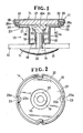
- the present invention is particularly useful when embodied in a button such as shown in Figure 1, generally indicated by the numeral 10.
- the button 10 comprises a capped button body 11 and a tack member 12 attaching the button 10 to a garment fabric 13.
- the button body 11 includes a substantially funnel-shaped button back 14 composed of an annular head 15 and a hollow stem 16 projecting downwardly from an inner edge of the annular head 15.
- the hollow stem 16 is in the form of a double tube of circular cross section which is composed of a pair of concentric inner and outer tubes 17, 18 joined at their lower end by an annular turn 19.
- the inner tube 18 has at its upper end an outwardly directed annular flange 20.
- the annular head 15 is composed of a substantially circular flange portion 21 leading from an upper end of the outer tube 18, and an inclined annular peripheral portion 22 extending radially outwardly and axially from the flange portion 21.
- the flange portion. 21 extends substantially per- pendicularlyto the axis of the hollow stem 16 and lies in a plane extending above the plane of the flange 20.
- the peripheral portion 22 has a plurality of ribs 23 (four being shown in Figure 2) extending across the annular peripheral portion 22, the ribs 23 being angularly spaced at equal angular intervals.
- the ribs 23 are formed by pressing portions out of the peripheral portion 22 toward the center of the annular head 15. Therefore, each of the ribs 23 provides a groove 23a opening radially outwardly away from the center of the head 15 and an opposite ridge 23b projecting radially inwardly toward the center of the head 15, as shown in Figure 2.
- the button body 11 also includes a cap 24 mounted on the head 15 of the button back 14, and a circular plate 25 sandwiched between the head 15 and the cap 24.
- the back plate 25 has in its one surface a plurality of radially extending slots 26 (three being shown in Figure 1), and is placed on the flange portion 21 of the head 15 with the slots 26 opening toward the stem 16.
- the tack member 12, the button back 14 and the cap 24 are preferably made of brass, and the back plate 25 is preferably made of iron or steel.
- the back plate 15 has a thickness which is larger than the width of the annular peripheral portion 22 of the head 15 so that the back plate 25 projects upwardly beyond the head 15.
- the cap 24 includes a substantially flat upper wall 27 and an inclined annular rim 28 extending radially inwardly and axially from an outer circumferential edge-of the upper wall 27.
- the annular rim 28 of the cap 24 prior to being mounted on the button back's head 15 is somewhat distorted.
- the cap 24 is first placed on the head 15 with the upper wall 27 supported on the back plate 25. Then, the annular rim 28 is deformed as by a presser tool (not shown) radially inwardly into the shape shown in Figure 1 until the annular rim 28 is firmly pressed against the peripheral portion 22. During that time, the annular rim 28 is recessed at its portions corresponding to the ribs 23 on the peripheral portion 22 so that four protrusions 28a are formed on the annular rim 28. Each of the protrusions 28a projects into a corresponding one of the grooves 23a of the respective ribs 23, and terminates short of the bottom of the groove 23a.
- the button body 11 thus assembled has an annular space 29 defined between the upper wall 28 of the cap 24 and an edge of the peripheral portion 22, and channels 30 defined respectively between the ribs 23 and the protrusions 28a, the channels 30 communicating with the annular space 29.
- the tack member 12 before having been joined with the button body 11 includes a head 31 and a shank 32 of circular cross section projecting perpendicularly and centrally from the head 31 for being inserted through the hollow stem 16 of the button back 14.
- the shank 32 has a pointed tip end.
- the shank 32 of the tack member 12 is pierced through the garment fabric 13 and is then inserted through the inner tube 17 of the button back's hollow stem 16. With continued insertion of the shank 32, the tip end of the shank 32 is deformed into an enlarged foot 32a compressed axially and spreaded radially between the back plate 25 and the annular flange 20 of the inner tube. The enlarged foot 32a has portions received in the slots 26 in the back plate 25.
- a liquid such as water or a solution which has entered in the hollow interior of the button 10 during washing or dyeing of the garment fabric 13, can be drawn off the button's hollow interior through a continuous passage defined jointly by the slots 26, the space 29 and the channels 30.
- the button body 11 is prevented from being rotated with respect to the tack member 12. Further, rotation of the cap 24 with respect to the button back 14 is prevented by the protrusions 28a held in engagement with the rib's grooves 23a.
- a modified button 33 shown in Figure 3 is substantially similar to the button 10 shown in Figure 1, but is different therefrom in that a button body 34 includes a button back 35 having a plurality of ribs 36 (two being shown) extending on and radially across an annular flange portion 37 of the button back 35, the ribs 36 being spaced at equal angular intervals.
- a back plate 38 has an opposite flate surface and is disposed on the ribs 36 of the button back's flange portion 37.
- a liquid which has been entrapped in the hollow interior of the button 34 can be drawn off through spaces defined between adjacent ribs 36 and the back plate 38, a space 39 between an inclined annular peripheral portion 40 of the button back 35 and an upper wall 41 of a cap 42, and channels 43 between the peripheral portion 40 and an annular rim 44 of the cap 42.
Landscapes
- Details Of Garments (AREA)
- Slide Fasteners, Snap Fasteners, And Hook Fasteners (AREA)
- Purses, Travelling Bags, Baskets, Or Suitcases (AREA)
- Adornments (AREA)
Applications Claiming Priority (2)
| Application Number | Priority Date | Filing Date | Title |
|---|---|---|---|
| JP144884/82 | 1982-09-25 | ||
| JP1982144884U JPS5948215U (ja) | 1982-09-25 | 1982-09-25 | 被服用釦 |
Publications (2)
| Publication Number | Publication Date |
|---|---|
| EP0104568A1 EP0104568A1 (en) | 1984-04-04 |
| EP0104568B1 true EP0104568B1 (en) | 1986-05-07 |
Family
ID=15372603
Family Applications (1)
| Application Number | Title | Priority Date | Filing Date |
|---|---|---|---|
| EP83109240A Expired EP0104568B1 (en) | 1982-09-25 | 1983-09-19 | Button |
Country Status (8)
| Country | Link |
|---|---|
| US (1) | US4571781A (es) |
| EP (1) | EP0104568B1 (es) |
| JP (1) | JPS5948215U (es) |
| KR (1) | KR850001280Y1 (es) |
| AU (1) | AU541523B2 (es) |
| DE (2) | DE104568T1 (es) |
| ES (1) | ES274470Y (es) |
| GB (1) | GB2127672B (es) |
Families Citing this family (11)
| Publication number | Priority date | Publication date | Assignee | Title |
|---|---|---|---|---|
| JPS59166711U (ja) * | 1983-04-26 | 1984-11-08 | 日本ノ−シヨン工業株式会社 | 被服等用釦 |
| FR2579985B1 (es) * | 1985-04-05 | 1988-07-15 | Inst Francais Du Petrole | |
| JPH038086Y2 (es) * | 1986-03-13 | 1991-02-28 | ||
| US5414910A (en) * | 1991-07-29 | 1995-05-16 | Berman Pearl Button Company, Inc. | Decorative multi-part ornamentations having a collar element |
| US5255417A (en) * | 1991-07-29 | 1993-10-26 | Herman Pearl Button Co., Inc. | Decorative multi-part ornamentations and the fabrication thereof |
| US5542157A (en) * | 1991-07-29 | 1996-08-06 | Herman Pearl Button Company, Inc. | Decorative multi-part button assemblies and use thereof |
| US5526551A (en) * | 1991-07-29 | 1996-06-18 | Herman Pearl Button Co., Inc. | Decorative multi-part assemblies having an interconnector |
| US5315739A (en) * | 1991-07-29 | 1994-05-31 | Herman Pearl Button Co., Inc. | Decorative multi-part ornamentations and the fabrication thereof |
| US7814624B2 (en) * | 2007-01-23 | 2010-10-19 | Ykk Corporation | Self draining snap fastener sockets |
| US20100175226A1 (en) * | 2009-01-12 | 2010-07-15 | Foo-Yuen Wong | Two-component tack button |
| KR101337848B1 (ko) * | 2012-01-03 | 2013-12-06 | 정재욱 | 가방 끈 구멍쇠 구조 |
Family Cites Families (15)
| Publication number | Priority date | Publication date | Assignee | Title |
|---|---|---|---|---|
| US358080A (en) * | 1887-02-22 | Changeable button | ||
| US1305275A (en) * | 1919-06-03 | Canada | ||
| US1270467A (en) * | 1918-02-08 | 1918-06-25 | Waterbury Button Company | Button. |
| DE324285C (de) * | 1919-04-12 | 1920-08-30 | Josef Graczyk | Knopf |
| US1702768A (en) * | 1928-01-12 | 1929-02-19 | Universal Button Fastening & B | Button |
| US1867424A (en) * | 1932-04-12 | 1932-07-12 | Fulford Mfg Co | Cover and initial mounting |
| DE675476C (de) * | 1935-05-11 | 1939-05-09 | Gust Rafflenbeul Fa | Druckknopf mit Nadelbefestigung |
| US2072218A (en) * | 1935-06-07 | 1937-03-02 | Patent Button Co | Novelty button |
| US2067222A (en) * | 1935-12-12 | 1937-01-12 | Scovill Manufacturing Co | Button or the like |
| US2179522A (en) * | 1939-07-22 | 1939-11-14 | Patent Button Co | Tack button |
| US2254446A (en) * | 1940-10-23 | 1941-09-02 | Patent Button Co | Reinforced plastic staple button |
| US2574436A (en) * | 1949-02-12 | 1951-11-06 | Scovill Manufacturing Co | Closed type burr |
| US3249974A (en) * | 1964-01-02 | 1966-05-10 | Patrick J Connolly | Ornamental button |
| DE2738703A1 (de) * | 1977-08-27 | 1979-03-01 | Schaeffer Homberg Gmbh | Vernietbarer knopf |
| GB2029690A (en) * | 1978-09-15 | 1980-03-26 | Hidenosuke Ishizaki | Button |
-
1982
- 1982-09-25 JP JP1982144884U patent/JPS5948215U/ja active Pending
-
1983
- 1983-09-08 AU AU18929/83A patent/AU541523B2/en not_active Ceased
- 1983-09-14 GB GB08324552A patent/GB2127672B/en not_active Expired
- 1983-09-17 KR KR2019830008146U patent/KR850001280Y1/ko not_active Expired
- 1983-09-19 EP EP83109240A patent/EP0104568B1/en not_active Expired
- 1983-09-19 DE DE198383109240T patent/DE104568T1/de active Pending
- 1983-09-19 DE DE8383109240T patent/DE3363414D1/de not_active Expired
- 1983-09-21 ES ES1983274470U patent/ES274470Y/es not_active Expired
- 1983-09-23 US US06/535,080 patent/US4571781A/en not_active Expired - Fee Related
Also Published As
| Publication number | Publication date |
|---|---|
| GB2127672A (en) | 1984-04-18 |
| DE104568T1 (de) | 1984-08-16 |
| JPS5948215U (ja) | 1984-03-30 |
| GB2127672B (en) | 1985-08-07 |
| EP0104568A1 (en) | 1984-04-04 |
| ES274470Y (es) | 1984-08-16 |
| DE3363414D1 (en) | 1986-06-12 |
| ES274470U (es) | 1984-01-16 |
| AU541523B2 (en) | 1985-01-10 |
| AU1892983A (en) | 1984-05-17 |
| KR840006060U (ko) | 1984-11-30 |
| KR850001280Y1 (ko) | 1985-06-21 |
| GB8324552D0 (en) | 1983-10-19 |
| US4571781A (en) | 1986-02-25 |
Similar Documents
| Publication | Publication Date | Title |
|---|---|---|
| EP0104568B1 (en) | Button | |
| CA1146340A (en) | Fabric-covered button | |
| US4706344A (en) | Button assembly | |
| US4570307A (en) | Button having plate for deflecting an attaching tack | |
| EP0101065A1 (en) | Button | |
| EP0191424B1 (en) | Socket element assembly for snap fasteners | |
| GB2094613A (en) | Snap-fit button | |
| EP0123215B1 (en) | Button | |
| EP0179293A1 (en) | Button | |
| KR870003050Y1 (ko) | 피복단추 | |
| CA1317743C (en) | Button | |
| EP0169660B1 (en) | Button | |
| US5115548A (en) | Button for use on garments and the like | |
| EP0174606A2 (en) | A button assembly for attachment to a garment fabric | |
| US4299019A (en) | Die-set combination for making pin-back badges | |
| GB2167150A (en) | Capped eyelet for attaching press studs to garments | |
| CA1295456C (en) | Open-faced button | |
| CA1170223A (en) | Grommet-applying tool | |
| EP0170852B1 (en) | Magnetic button for articles of clothing, leather goods, and the like | |
| EP0080697A1 (en) | Grommet | |
| US4747189A (en) | Swivel-head button | |
| GB2151740A (en) | A capped eyelet for attaching press studs to garments | |
| HK28892A (en) | Open-faced button | |
| WO1992017083A1 (en) | Fastener | |
| JPH09252810A (ja) | 服飾用リベット部材 |
Legal Events
| Date | Code | Title | Description |
|---|---|---|---|
| PUAI | Public reference made under article 153(3) epc to a published international application that has entered the european phase |
Free format text: ORIGINAL CODE: 0009012 |
|
| AK | Designated contracting states |
Designated state(s): BE CH DE FR IT LI NL SE |
|
| ITCL | It: translation for ep claims filed |
Representative=s name: JACOBACCI CASETTA & PERANI S.P.A. |
|
| TCNL | Nl: translation of patent claims filed | ||
| EL | Fr: translation of claims filed | ||
| DET | De: translation of patent claims | ||
| 17P | Request for examination filed |
Effective date: 19840713 |
|
| GRAA | (expected) grant |
Free format text: ORIGINAL CODE: 0009210 |
|
| AK | Designated contracting states |
Kind code of ref document: B1 Designated state(s): BE CH DE FR IT LI NL SE |
|
| ITF | It: translation for a ep patent filed | ||
| REF | Corresponds to: |
Ref document number: 3363414 Country of ref document: DE Date of ref document: 19860612 |
|
| ET | Fr: translation filed | ||
| PG25 | Lapsed in a contracting state [announced via postgrant information from national office to epo] |
Ref country code: SE Effective date: 19860920 |
|
| PG25 | Lapsed in a contracting state [announced via postgrant information from national office to epo] |
Ref country code: LI Effective date: 19860930 Ref country code: CH Effective date: 19860930 |
|
| PLBE | No opposition filed within time limit |
Free format text: ORIGINAL CODE: 0009261 |
|
| STAA | Information on the status of an ep patent application or granted ep patent |
Free format text: STATUS: NO OPPOSITION FILED WITHIN TIME LIMIT |
|
| PG25 | Lapsed in a contracting state [announced via postgrant information from national office to epo] |
Ref country code: NL Effective date: 19870401 |
|
| 26N | No opposition filed | ||
| NLV4 | Nl: lapsed or anulled due to non-payment of the annual fee | ||
| REG | Reference to a national code |
Ref country code: CH Ref legal event code: PL |
|
| PG25 | Lapsed in a contracting state [announced via postgrant information from national office to epo] |
Ref country code: BE Effective date: 19870930 |
|
| BERE | Be: lapsed |
Owner name: NIPPON NOTION KOGYO CO. LTD. Effective date: 19870930 |
|
| PG25 | Lapsed in a contracting state [announced via postgrant information from national office to epo] |
Ref country code: FR Free format text: LAPSE BECAUSE OF NON-PAYMENT OF DUE FEES Effective date: 19880531 |
|
| PG25 | Lapsed in a contracting state [announced via postgrant information from national office to epo] |
Ref country code: DE Effective date: 19880601 |
|
| REG | Reference to a national code |
Ref country code: FR Ref legal event code: ST |
|
| EUG | Se: european patent has lapsed |
Ref document number: 83109240.8 Effective date: 19870812 |