EP0104174B1 - Deformierbare haubenstruktur für eine gasturbinenbefestigung - Google Patents
Deformierbare haubenstruktur für eine gasturbinenbefestigung Download PDFInfo
- Publication number
- EP0104174B1 EP0104174B1 EP19820901798 EP82901798A EP0104174B1 EP 0104174 B1 EP0104174 B1 EP 0104174B1 EP 19820901798 EP19820901798 EP 19820901798 EP 82901798 A EP82901798 A EP 82901798A EP 0104174 B1 EP0104174 B1 EP 0104174B1
- Authority
- EP
- European Patent Office
- Prior art keywords
- strut
- belt
- hinge
- linkage
- cowl
- Prior art date
- Legal status (The legal status is an assumption and is not a legal conclusion. Google has not performed a legal analysis and makes no representation as to the accuracy of the status listed.)
- Expired
Links
- 230000006835 compression Effects 0.000 claims 2
- 238000007906 compression Methods 0.000 claims 2
- 239000000446 fuel Substances 0.000 abstract description 5
- 239000000463 material Substances 0.000 abstract description 5
- 230000009528 severe injury Effects 0.000 abstract 1
- 238000006243 chemical reaction Methods 0.000 description 3
- 229920000271 Kevlar® Polymers 0.000 description 2
- 239000004761 kevlar Substances 0.000 description 2
- 238000010521 absorption reaction Methods 0.000 description 1
- 238000010276 construction Methods 0.000 description 1
- 238000006073 displacement reaction Methods 0.000 description 1
- 230000033001 locomotion Effects 0.000 description 1
- 238000012986 modification Methods 0.000 description 1
- 230000004048 modification Effects 0.000 description 1
- 238000011084 recovery Methods 0.000 description 1
- 230000000452 restraining effect Effects 0.000 description 1
Images


Classifications
-
- B—PERFORMING OPERATIONS; TRANSPORTING
- B64—AIRCRAFT; AVIATION; COSMONAUTICS
- B64D—EQUIPMENT FOR FITTING IN OR TO AIRCRAFT; FLIGHT SUITS; PARACHUTES; ARRANGEMENT OR MOUNTING OF POWER PLANTS OR PROPULSION TRANSMISSIONS IN AIRCRAFT
- B64D29/00—Power-plant nacelles, fairings or cowlings
-
- B—PERFORMING OPERATIONS; TRANSPORTING
- B64—AIRCRAFT; AVIATION; COSMONAUTICS
- B64D—EQUIPMENT FOR FITTING IN OR TO AIRCRAFT; FLIGHT SUITS; PARACHUTES; ARRANGEMENT OR MOUNTING OF POWER PLANTS OR PROPULSION TRANSMISSIONS IN AIRCRAFT
- B64D27/00—Arrangement or mounting of power plants in aircraft; Aircraft characterised by the type or position of power plants
- B64D27/02—Aircraft characterised by the type or position of power plants
- B64D27/16—Aircraft characterised by the type or position of power plants of jet type
- B64D27/18—Aircraft characterised by the type or position of power plants of jet type within, or attached to, wings
-
- F—MECHANICAL ENGINEERING; LIGHTING; HEATING; WEAPONS; BLASTING
- F01—MACHINES OR ENGINES IN GENERAL; ENGINE PLANTS IN GENERAL; STEAM ENGINES
- F01D—NON-POSITIVE DISPLACEMENT MACHINES OR ENGINES, e.g. STEAM TURBINES
- F01D21/00—Shutting-down of machines or engines, e.g. in emergency; Regulating, controlling, or safety means not otherwise provided for
- F01D21/04—Shutting-down of machines or engines, e.g. in emergency; Regulating, controlling, or safety means not otherwise provided for responsive to undesired position of rotor relative to stator or to breaking-off of a part of the rotor, e.g. indicating such position
- F01D21/045—Shutting-down of machines or engines, e.g. in emergency; Regulating, controlling, or safety means not otherwise provided for responsive to undesired position of rotor relative to stator or to breaking-off of a part of the rotor, e.g. indicating such position special arrangements in stators or in rotors dealing with breaking-off of part of rotor
-
- F—MECHANICAL ENGINEERING; LIGHTING; HEATING; WEAPONS; BLASTING
- F05—INDEXING SCHEMES RELATING TO ENGINES OR PUMPS IN VARIOUS SUBCLASSES OF CLASSES F01-F04
- F05B—INDEXING SCHEME RELATING TO WIND, SPRING, WEIGHT, INERTIA OR LIKE MOTORS, TO MACHINES OR ENGINES FOR LIQUIDS COVERED BY SUBCLASSES F03B, F03D AND F03G
- F05B2260/00—Function
- F05B2260/30—Retaining components in desired mutual position
- F05B2260/301—Retaining bolts or nuts
- F05B2260/3011—Retaining bolts or nuts of the frangible or shear type
-
- F—MECHANICAL ENGINEERING; LIGHTING; HEATING; WEAPONS; BLASTING
- F05—INDEXING SCHEMES RELATING TO ENGINES OR PUMPS IN VARIOUS SUBCLASSES OF CLASSES F01-F04
- F05D—INDEXING SCHEME FOR ASPECTS RELATING TO NON-POSITIVE-DISPLACEMENT MACHINES OR ENGINES, GAS-TURBINES OR JET-PROPULSION PLANTS
- F05D2220/00—Application
- F05D2220/30—Application in turbines
- F05D2220/32—Application in turbines in gas turbines
- F05D2220/327—Application in turbines in gas turbines to drive shrouded, high solidity propeller
Definitions
- the invention relates to a cowl hinge support structure as defined in the preamble of claim 1.
- a support structure is generally used and for example shown in US-A-4 055 041.
- belt made of strong flexible material surrounding the engine fan area.
- This flexible belt serves to restrain, contain and catch all flying debris which is ingested by the engine or originated from broken fan pieces which, when not restrained, could damage, cut or short out the engine fuel, oil, electrical. and other supply lines causing engine fire and related disasters.
- the belt is made somewhat similar to the construction of a bullet proof vest, utilizing layers of tough, flexible Kevlar material or the like and capable of restraining or containing most of the free flying objects.
- the invention has for its object to provide a cowl hinge support structure which is adapted to the use of a flexible containment belt and further reduces the safety risks due to free flying objects in the fan area.
- the airplane strut structure which supports the engine includes a cowl hinge structure.
- the engine cowlings are hingedly attached to the right and to the left side of the cowl hinge structure.
- the present invention provides for a safety collapsible cowl hinge structure in the area of the engine fan so that upon fan belt deflection, due to fan blade failings or other debris, the deflection will not cause damage to structural areas carrying fuel and electrical conduits, but the deflection force is contained and absorbed in the nearest located cowl hinge structure due to its collapsible capability.
- the cowl hinge structure is partly located within the maximum deflection envelope of the fan protection belt, which location approximately coincides with the forward strut-engine area.
- the cowl hinge structure includes a substantially horizontally positioned hinge beam which carries at each end a thereon mounted cowl hinge.
- the hinge beam is connected to the strut structure by a right and a left collapsible triangular structural arrangement, comprising a right and a left vertically extending beam-chord linkage between the hinge beam and the right and left strut chord.
- each beam-chord is pivotally mounted to the hinge beam and solidly connected via a breakaway mechanical fuse arrangement to the right and left chord, respectively.
- the breakaway arrangement at the upper part of the linkages employs a bracket provided with a riveted, mounted locking clip, , which rivets will shear and cause a disconnection at an upward force or load.
- a right and a left tension load linkage is substantially diagonally mounted between the linkage beam and the upper portion of the chord beam linkage thus forming the right and left triangular configuration.
- the tension linkage mountings at the hinge beam are slidably arranged while the connection to the upper portion of the beam-chord linkage is pivotally arranged.
- the hinge beam when a belt deflection occurs, the hinge beam will be dislocated in a substantially upward direction which causes a disconnection at the breakaway bracket connections and successively pivoting and sliding motions at the various linkage connections and thereafter a substantially realignment and repositioning of the cowl hinge structure due to the recovery or reaction forces of the temporarily upset cowling structures.
- the strut structure, strut chords and the strut fairing have not been harmed, while the fairing structures between the cowling and the forward strut fairing may break away and will have to be replaced, however, such damage is insignificant in comparison to the prevented possible disaster and/or structural damage that would occur without the utilization of the herein disclosed invention.
- gas-turbine engines 10 which are mounted by struts 12 to the wing 14, as illustrated in Figure 1.
- struts 12 Within the engine intake area 16 is a high speed rotating fan blade assembly carrying fan blades 18.
- the cowl hinge structure 30 is adjacent engine fuel 50 conduits, oil conduit 52 and other hydraulic or electrical connections which, via the conventional fire wall 32, bypass the structure 30 towards other engine locations (not shown).
- upset or dislocation of a conventional cowl hinge support structure which was integrally connected with the strut structure 12 would cause immediate danger through severed fuel and shorted electrical conduits.
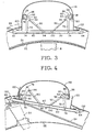
- the presently disclosed cowl hinge structure 30 has been made collapsible and thus may become independent of the strut structure 12 and its main support chords 34 and 36, as illustrated in Figure 4.
- the collapsible cowl hinge structure 30 comprises a horizontally positioned hinge beam 60 carrying a left and a right cowl hinge 62 and 64.
- the beam 60 is mounted to the strut chords 34 and 36 by a breakaway means or mechanical fuse arrangement 66 and 68.
- the particular arrangement may be accomplished many different conventional ways, however, the preferred arrangement is shown in Figures 2-6 and in detail in Figures 5 and 6.
- the beam-chord linkages 70 and 72 are pivotally connected to the beam 60 by bolts 74-76 and at their upper ends by bolts 78-80, kept within brackets 82 and 84 and clips 86 and 88.
- the clip 86 or 88 is riveted by rivets 91, which will shear when an upwards directed load occurs, thus disconnecting the beam-chord linkage 70 or 72 from the strut structure 12.
- Diagonally positioned tension load linkages 90 and 92 are pivotally mounted to the upper portion of the beam-chord linkage and are slidably mounted to the beam at the openings 98 and 100. Upon collapsing action, the tension load linkages 90 and 92 may travel through the beam openings 98 and 100 as illustrated in Figure 4.
- connection to the beam 60 is made via a bolt 102, and the tension linkage 104 is made of a thin, foldable tension load material so that the linkage 104 may fold upon action and unfold due to the cowling reaction repositioning forces.
- the embodiment shown in Figure 8 comprises a sturdier diagonal tension linkage 110 which is connected to the beam 60 at one or both ends by a breakway or mechanical fuse bolt 112 which will shear at a predetermined load.
- the maximum deflection envelope 26 as illustrated in Figure 4, where the belt hits the beam at the hinge 62 is just an exemplary showing. The point of impact may occur anywhere along the length of the beam 60. Also, it should be noted that the strut fairing 118, the strut chords 34 and 36 remain in their original location, since they are being part of the strut structure 12. The fairing structures 120 and 122 will become folded and damaged and will have to be replaced. The reaction load 128 which is due primarily to the upset of the cowl hinge 62 and/or 64 and its thereon connected cowling structures 130 and/or 132, will reposition the collapsed cowl hinge structure 30, as a moveable mechanism, into the approximate original position as shown in Figure 3.
Landscapes
- Engineering & Computer Science (AREA)
- Aviation & Aerospace Engineering (AREA)
- Mechanical Engineering (AREA)
- General Engineering & Computer Science (AREA)
- Structures Of Non-Positive Displacement Pumps (AREA)
- Body Structure For Vehicles (AREA)
Claims (5)
Applications Claiming Priority (1)
| Application Number | Priority Date | Filing Date | Title |
|---|---|---|---|
| PCT/US1982/000373 WO1983003396A1 (en) | 1982-03-26 | 1982-03-26 | Collapsible cowl structure for gas-turbine engine strut |
Publications (3)
| Publication Number | Publication Date |
|---|---|
| EP0104174A1 EP0104174A1 (de) | 1984-04-04 |
| EP0104174A4 EP0104174A4 (de) | 1985-07-30 |
| EP0104174B1 true EP0104174B1 (de) | 1987-12-16 |
Family
ID=22167887
Family Applications (1)
| Application Number | Title | Priority Date | Filing Date |
|---|---|---|---|
| EP19820901798 Expired EP0104174B1 (de) | 1982-03-26 | 1982-03-26 | Deformierbare haubenstruktur für eine gasturbinenbefestigung |
Country Status (3)
| Country | Link |
|---|---|
| EP (1) | EP0104174B1 (de) |
| DE (1) | DE3277836D1 (de) |
| WO (1) | WO1983003396A1 (de) |
Families Citing this family (3)
| Publication number | Priority date | Publication date | Assignee | Title |
|---|---|---|---|---|
| GB9921935D0 (en) * | 1999-09-17 | 1999-11-17 | Rolls Royce | A nacelle assembly for a gas turbine engine |
| US6695574B1 (en) * | 2002-08-21 | 2004-02-24 | Pratt & Whitney Canada Corp. | Energy absorber and deflection device |
| US10815679B2 (en) * | 2017-01-27 | 2020-10-27 | The Boeing Company | System for four collaborative robots and humans in a narrowing work envelope |
Family Cites Families (2)
| Publication number | Priority date | Publication date | Assignee | Title |
|---|---|---|---|---|
| US4055041A (en) * | 1974-11-08 | 1977-10-25 | The United States Of America As Represented By The Administrator Of The National Aeronautics And Space Administration | Integrated gas turbine engine-nacelle |
| GB1521847A (en) * | 1976-04-30 | 1978-08-16 | Rolls Royce | Attachment for attaching jet propulsion engines to vehicle structure |
-
1982
- 1982-03-26 EP EP19820901798 patent/EP0104174B1/de not_active Expired
- 1982-03-26 WO PCT/US1982/000373 patent/WO1983003396A1/en not_active Ceased
- 1982-03-26 DE DE8282901798T patent/DE3277836D1/de not_active Expired
Also Published As
| Publication number | Publication date |
|---|---|
| DE3277836D1 (en) | 1988-01-28 |
| EP0104174A4 (de) | 1985-07-30 |
| WO1983003396A1 (en) | 1983-10-13 |
| EP0104174A1 (de) | 1984-04-04 |
Similar Documents
| Publication | Publication Date | Title |
|---|---|---|
| US4474346A (en) | Collapsible cowl structure for gas-turbine engine strut | |
| EP2103516B1 (de) | Montagesystem für einen Gasturbinenmotor | |
| US4875655A (en) | Vibration isolating engine mount | |
| JP4498694B2 (ja) | 単一のスラストリンクを有する航空機エンジンマウント | |
| US5921500A (en) | Integrated failsafe engine mount | |
| US6401448B1 (en) | System for mounting aircraft engines | |
| RU2468963C2 (ru) | Опорная рама корпуса вентилятора, установленная на пилоне крепления и на воздухозаборнике гондолы | |
| JP4936672B2 (ja) | フェールセーフ航空機エンジン取付けシステム | |
| US5927644A (en) | Double failsafe engine mount | |
| EP0147878B1 (de) | Montagesystem für ein Düsentriebwerk | |
| US5174525A (en) | Structure for eliminating lift load bending in engine core of turbofan | |
| EP2080879B1 (de) | System zur Montage einer Gasturbine | |
| US7267301B2 (en) | Aircraft engine with means of suspension from the structure of an aircraft | |
| EP0872418B1 (de) | Ausfallsichere Triebwerksaufhängung durch drei Gestänge mit drei Hebeln | |
| US5871175A (en) | Redundant front suspension system for a turboshaft engine | |
| US7108224B2 (en) | Aircraft engine rear suspension with thrust recovery | |
| US5871176A (en) | Redundant front suspension system for a turboshaft engine | |
| US5028001A (en) | Method of vibration isolating an aircraft engine | |
| US8727269B2 (en) | System and method for mounting an aircraft engine | |
| EP0564126A1 (de) | Schubbefestigung eines Triebwerkes an einem Luftfahrzeug | |
| US10246196B2 (en) | Aircraft engine assembly comprising at least two rear engine attachments axially shifted from each other | |
| US5035379A (en) | Movable aircraft engine cowling | |
| EP1013896A2 (de) | Turbinenlager | |
| US4392622A (en) | Combined beam support for landing gear | |
| WO2009134513A2 (en) | Aircraft flight termination system and method |
Legal Events
| Date | Code | Title | Description |
|---|---|---|---|
| PUAI | Public reference made under article 153(3) epc to a published international application that has entered the european phase |
Free format text: ORIGINAL CODE: 0009012 |
|
| 17P | Request for examination filed |
Effective date: 19830506 |
|
| AK | Designated contracting states |
Kind code of ref document: A1 Designated state(s): DE FR GB NL SE |
|
| 17Q | First examination report despatched |
Effective date: 19860627 |
|
| GRAA | (expected) grant |
Free format text: ORIGINAL CODE: 0009210 |
|
| AK | Designated contracting states |
Kind code of ref document: B1 Designated state(s): DE FR GB NL SE |
|
| PG25 | Lapsed in a contracting state [announced via postgrant information from national office to epo] |
Ref country code: SE Effective date: 19871231 |
|
| ET | Fr: translation filed | ||
| REF | Corresponds to: |
Ref document number: 3277836 Country of ref document: DE Date of ref document: 19880128 |
|
| PLBE | No opposition filed within time limit |
Free format text: ORIGINAL CODE: 0009261 |
|
| STAA | Information on the status of an ep patent application or granted ep patent |
Free format text: STATUS: NO OPPOSITION FILED WITHIN TIME LIMIT |
|
| 26N | No opposition filed | ||
| PGFP | Annual fee paid to national office [announced via postgrant information from national office to epo] |
Ref country code: GB Payment date: 19910305 Year of fee payment: 10 |
|
| PGFP | Annual fee paid to national office [announced via postgrant information from national office to epo] |
Ref country code: DE Payment date: 19910328 Year of fee payment: 10 |
|
| PGFP | Annual fee paid to national office [announced via postgrant information from national office to epo] |
Ref country code: NL Payment date: 19910331 Year of fee payment: 10 |
|
| PGFP | Annual fee paid to national office [announced via postgrant information from national office to epo] |
Ref country code: FR Payment date: 19911231 Year of fee payment: 11 |
|
| PG25 | Lapsed in a contracting state [announced via postgrant information from national office to epo] |
Ref country code: GB Effective date: 19920326 |
|
| PG25 | Lapsed in a contracting state [announced via postgrant information from national office to epo] |
Ref country code: NL Effective date: 19921001 |
|
| NLV4 | Nl: lapsed or anulled due to non-payment of the annual fee | ||
| GBPC | Gb: european patent ceased through non-payment of renewal fee | ||
| PG25 | Lapsed in a contracting state [announced via postgrant information from national office to epo] |
Ref country code: FR Effective date: 19921130 |
|
| PG25 | Lapsed in a contracting state [announced via postgrant information from national office to epo] |
Ref country code: DE Effective date: 19921201 |
|
| REG | Reference to a national code |
Ref country code: FR Ref legal event code: ST |