EP0104045B1 - Procédé pour étancher des câbles électriques à pression sous maintenance de la pression - Google Patents
Procédé pour étancher des câbles électriques à pression sous maintenance de la pression Download PDFInfo
- Publication number
- EP0104045B1 EP0104045B1 EP83305376A EP83305376A EP0104045B1 EP 0104045 B1 EP0104045 B1 EP 0104045B1 EP 83305376 A EP83305376 A EP 83305376A EP 83305376 A EP83305376 A EP 83305376A EP 0104045 B1 EP0104045 B1 EP 0104045B1
- Authority
- EP
- European Patent Office
- Prior art keywords
- gas
- cable
- pressure
- sealably
- exposed
- Prior art date
- Legal status (The legal status is an assumption and is not a legal conclusion. Google has not performed a legal analysis and makes no representation as to the accuracy of the status listed.)
- Expired
Links
Images
Classifications
-
- H—ELECTRICITY
- H02—GENERATION; CONVERSION OR DISTRIBUTION OF ELECTRIC POWER
- H02G—INSTALLATION OF ELECTRIC CABLES OR LINES, OR OF COMBINED OPTICAL AND ELECTRIC CABLES OR LINES
- H02G15/00—Cable fittings
- H02G15/20—Cable fittings for cables filled with or surrounded by gas or oil
- H02G15/24—Cable junctions
-
- H—ELECTRICITY
- H02—GENERATION; CONVERSION OR DISTRIBUTION OF ELECTRIC POWER
- H02G—INSTALLATION OF ELECTRIC CABLES OR LINES, OR OF COMBINED OPTICAL AND ELECTRIC CABLES OR LINES
- H02G1/00—Methods or apparatus specially adapted for installing, maintaining, repairing or dismantling electric cables or lines
- H02G1/14—Methods or apparatus specially adapted for installing, maintaining, repairing or dismantling electric cables or lines for joining or terminating cables
Definitions
- This invention relates generally to sealing techniques of electrical cables and specifically to a method of sealing a gas-pressurized electrical cable while under pressure.
- Multiple conductor electrical cables such as telephone cables, typically include bundles of insulated wire conductors contained within a weather resistant outer sheath of lead, plastic or other protective materials. These cables are often buried under ground or mounted on supports above ground. To minimize deleterious electrical effects of insidious moisture leaks, it is now common practice to maintain a positive gas pressure, such as by air or nitrogen, to prevent inward leaks of moisture. While such gas pressurization is desirable in controlling moisture, problems arise in maintenance, repair and in making splices or connections of other cables thereto. In making a repair, for example, of a damaged outer sheath, or in splicing, it is often necessary to remove a portion of the sheath, exposing thereby the interiorly contained conductors.
- a positive gas pressure such as by air or nitrogen
- a method of sealing an exposed area of a gas pressurized electrical cable while under pressure comprising the steps of:
- a method of sealing an exposed portion of a gas pressurized electrical cable while under pressure comprising the steps of:
- a hollow tubular member defining the gas pressure escape vent is provided at the exposed cable portion, the tubular member hollow interior defining a gas-flow opening that is less in size than the exposed cable portion.
- the exposed cable portion and the vent exterior are then sealably covered such that the gas may escape through the escape vent opening.
- the vent opening is then sealably closed to effect the complete seal.
- a protective sleeve may then be applied over the sealed cable portion.
- the sealing method according to the invention permits repair or sealing of a gas pressurized cable without having to depressurize the entire cable, as is done presently in the art. In some instances, depressurization may have to occur over a distance of several kilometers and could take several hours to achieve, and the advantage of the method according to the invention can therefore be seen.
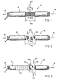
- a gas pressurized electrical cable 10 such as a telephone cable, comprising an outer sheath 12 of lead, plastic or other suitable material and containing a plurality of individually insulated conductors 14.
- the invention may also be practiced with single conductor cable having suitable gas channel means.
- a portion of the sheath 12 has been removed, thereby exposing the conductors 14, the exposed cable area being identified generally by numeral 10a between the spaced, severed sheath sections. Removal of the sheath portion is typically required in repair of damaged telephone cables or in making splices or other electrical connections as indicated by connectors 16. It is not uncommon for the length of the removed sheath (i.e., 10a) to be on the order of eight (8) inches (20.3 cm) and may be as much as several feet (meters).
- the cable 10 is of the type which, while part of a system, is maintained for moisture control under positive gas pressure, such as air or nitrogen, and typically at a pressure of about 10-12 Ib/in 2 (68.95-82.7 kN/ m 2 ).
- the gas flow within the cable is indicated by the arrows 18, while the gas escaping from the cable exposed portion 10a, due to the removal of the cable sheath portion, is indicated by arrows 20.
- the cable exposed portion 10a is repaired or otherwise sealed while the cable is maintained under pressure, the method of sealing being fully described with reference to Figures 2-6 of the drawing.
- the exposed cable portions 10a may be covered with a gas permeable material 22, such as muslin tape, or other suitable material to protect the conductors 14 and the connection area.
- a gas permeable material 22 such as muslin tape, or other suitable material to protect the conductors 14 and the connection area.
- the gas 20 passes through the muslin tape 22 applied thereover.
- a sealant material 24, in the form of a tape 24, is wrapped helically, in half- overlapping fashion, onto the sheath 12 and onto the muslin tape 22 over the exposed cable portion.
- the sealant material comprises two different materials including a sealant tape of butyl rubber and an adhesively coated pressure tape of polyester film. The butyl rubber tape is applied initially with the polyester pressure tape wrapped thereover. It should be appreciated that other sealant materials may be used in the practice of the invention and that one or more layers of such materials may be applied.
- a gas pressure escape vent 26 is placed onto the muslin tape 22.
- the vent 26 is preferably in the form of a hollow tubular member having an opening 26a that is substantially less than the exposed cable portion 10a through which the gas 20 escapes from the cable during repair or splicing.
- the vent 26, preferably formed of a plastic or rubber material, is placed on the muslin tape 22 such that the gas flow opening 26a is approximately transverse to the longitudinal axis of the cable 10. Wrapping of the sealant material 24 is then continued until the entire cable exposed portion is sealed as shown in Figure 4, the sealant material 24 being wrapped around the vent 26 to seal the exterior wall thereof.
- the vent 26 permits the gas 20 to escape, the entire exposed cable area 10a, with the exception of the vent opening 26a, is effectively sealed while the cable is under pressure, the gas 20 escaping through the vent opening 26a.
- vent opening 26a which may be on the order of inch (1.27 cm) diameter
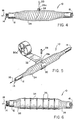
- complete sealing may be readily accomplished as shown in Figure 5.
- the projecting portion of the vent 26 is removed such that the vent upper surface is substantially flush with the outer surface of the sealant tape 24.
- a cylindrically shaped plug 28, preferably of butyl rubber, is formed for interfering insertion into the vent opening 26a.
- a film of adhesive pressure tape 30 of polyester or other suitable material is wrapped nearly fully around the sealant tape 24 without yet covering the vent opening 26a, and not severed from the roll 30a.
- a sealant pad 32 of butyl rubber is adhered to the adhesive side of the tape 30 such that when wrapping is resumed the pad 32 will cover the vent opening 26a.
- the plug 28 is then forcibly inserted into the vent opening 26a and the tape 30 with the sealant pad 32 thereon is quickly wrapped over the plugged vent opening 26, the tape being wrapped several times therearound in half-overlapped fashion to complete the cable seal.
- the tape 30 is then severed from the roll 30a.
- the cable 10 may be covered by a flexible, protective sleeve 34 which may be a longitudinally split sleeve that is compressively retained on the sealed cable as by fastening straps 36 of the self-locking type, the ends of the sleeve 34 being secured to the cable sheath 12 as by layers of tape 38.
- the sleeve 34 may be of the type as shown in GB-A-2075280 (corresponds to US-application, Serial No. 06/ 143,414, entitled "Protective Cover for Use in Sealed Cable Splices" and filed on April 24,1980).
- the advantages of the present sealing method should be appreciated.
- the primary advantage is the time and cost saved as a result of the seal being effected while the cable is under pressure.
- the tooling required to complete the sealing is minimal.
- the sealed cable, even with the protective sleeve thereon, remains flexible and can be reopened and resealed if necessary.
- the seal may be installed within a range of temperatures inasmuch as the sealing requirements are not temperature dependent. Also, in use, the pressure seal as provided herein will be maintained within a wide range of temperatures.
- a valve may be used in place of the tubular escape vent 26, which valve may be sealably closed to complete the seal.
- the exposed cable area through which the gas escapes may be reduced by covering the exposed area with a suitable sealant material except for a vent opening that is less than the area of the exposed portion. This material may be sealed such that all the exposed cable portion is sealed with the exception of the vent opening. This vent opening may then be covered and sealed as set forth hereinabove.
Landscapes
- Processing Of Terminals (AREA)
Claims (8)
Applications Claiming Priority (2)
| Application Number | Priority Date | Filing Date | Title |
|---|---|---|---|
| US419256 | 1982-09-17 | ||
| US06/419,256 US4545830A (en) | 1982-09-17 | 1982-09-17 | Method of sealing pressurized electrical cable while under pressure |
Publications (2)
| Publication Number | Publication Date |
|---|---|
| EP0104045A1 EP0104045A1 (fr) | 1984-03-28 |
| EP0104045B1 true EP0104045B1 (fr) | 1986-08-20 |
Family
ID=23661475
Family Applications (1)
| Application Number | Title | Priority Date | Filing Date |
|---|---|---|---|
| EP83305376A Expired EP0104045B1 (fr) | 1982-09-17 | 1983-09-14 | Procédé pour étancher des câbles électriques à pression sous maintenance de la pression |
Country Status (4)
| Country | Link |
|---|---|
| US (1) | US4545830A (fr) |
| EP (1) | EP0104045B1 (fr) |
| CA (1) | CA1203179A (fr) |
| DE (1) | DE3365457D1 (fr) |
Families Citing this family (15)
| Publication number | Priority date | Publication date | Assignee | Title |
|---|---|---|---|---|
| US4732628A (en) * | 1980-04-24 | 1988-03-22 | Thomas & Betts Corporation | Method of sealing and repairing electrical cables |
| US4681986A (en) * | 1986-02-24 | 1987-07-21 | Royston Laboratories, Inc. | Splice construction for electrical cable and method for making the same |
| US4885432A (en) * | 1987-04-06 | 1989-12-05 | Raychem Corporation | Splice case |
| US4818310A (en) * | 1987-05-05 | 1989-04-04 | Bell South Corporation | Pressurized cable splice closure apparatus and method |
| US4793877A (en) * | 1987-05-28 | 1988-12-27 | Thomas & Betts Corporation | Method for preventing water from tracking into a cable splice area |
| DE4241483A1 (de) * | 1992-12-09 | 1994-06-16 | Rxs Schrumpftech Garnituren | Verfahren zur Herstellung eines Sperrstopfens zur Längsabdichtung von Kabeln, insbesondere Lichtwellenleiter-Kabeln |
| US5613298A (en) * | 1995-01-17 | 1997-03-25 | Thomas & Betts Corporation | Forced encapsulation cable splice enclosure |
| US5802715A (en) * | 1995-01-17 | 1998-09-08 | Thomas & Betts Corporation | Method of sealing an elongate cable splice |
| AUPP936199A0 (en) * | 1999-03-23 | 1999-04-15 | Venardis, Nick John | Pipe repair method |
| US6737160B1 (en) * | 1999-12-20 | 2004-05-18 | The Regents Of The University Of California | Adhesive microstructure and method of forming same |
| KR101509786B1 (ko) * | 2009-09-28 | 2015-04-06 | 현대자동차주식회사 | 센서 포트 삽입형 실리콘 호스 및 그 제조방법 |
| JP6771974B2 (ja) * | 2016-07-15 | 2020-10-21 | コーニング リサーチ アンド ディヴェロップメント コーポレイション | クロージャの補修用部材、加熱部材、封止部材、及び、クロージャの補修方法。 |
| CN106786217B (zh) * | 2016-11-29 | 2020-07-28 | 中国电力科学研究院 | 配网电缆故障终端的绕包式应急抢修方法 |
| WO2020172415A1 (fr) * | 2019-02-22 | 2020-08-27 | TE Connectivity Services Gmbh | Systèmes et procédés de réparation de matériau d'étanchéité de couches de gaine externe de câbles et d'accessoires de câble |
| CN112234534B (zh) * | 2020-11-13 | 2022-06-24 | 华力通线缆股份有限公司 | 一种缠绕型电缆护套修补装置及其使用方法 |
Family Cites Families (17)
| Publication number | Priority date | Publication date | Assignee | Title |
|---|---|---|---|---|
| US763191A (en) * | 1903-12-02 | 1904-06-21 | Jesse B Marvin | Hose-mender. |
| US796781A (en) * | 1905-04-01 | 1905-08-08 | John Welsh | Process of repairing pipe-lines. |
| US1991230A (en) * | 1933-07-26 | 1935-02-12 | Gen Electric | Electric cable system and method of installing the same |
| US2253984A (en) * | 1938-08-10 | 1941-08-26 | Gen Electric | Gas filled cable and method of making the same |
| US2199552A (en) * | 1938-09-24 | 1940-05-07 | M B Skinner Company | High pressure vented guide plug clamp |
| US2259129A (en) * | 1939-05-02 | 1941-10-14 | Gen Electric | Gas filled cable |
| US2432568A (en) * | 1944-08-15 | 1947-12-16 | Phelps Dodge Copper Prod | Gas filled cable system |
| US2425851A (en) * | 1945-03-10 | 1947-08-19 | Phelps Dodge Copper Prod | Gas filled cable |
| US2492507A (en) * | 1945-10-24 | 1949-12-27 | John J Tipton | High-pressure pipe patch |
| US2655946A (en) * | 1949-06-02 | 1953-10-20 | Melvin P Morris | Valve for leak patching device for pipe lines |
| US2967795A (en) * | 1955-10-18 | 1961-01-10 | Minnesota Mining & Mfg | Protection of wire-splices |
| US3188121A (en) * | 1961-12-12 | 1965-06-08 | Rezolin Inc | Cable sheath pressure tap fitting |
| US3578896A (en) * | 1969-10-10 | 1971-05-18 | Thomas & Betts Corp | Electrical connector with fusible plug means and heating material |
| US3823250A (en) * | 1973-06-18 | 1974-07-09 | Hexcel Corp | Method and apparatus for constructing insulated cable pressure blocks |
| US4358634A (en) * | 1980-04-24 | 1982-11-09 | Thomas & Betts Corporation | Protective cover for use in sealed cable splices |
| FR2487595A1 (fr) * | 1980-07-25 | 1982-01-29 | Silec Liaisons Elec | Procede de realisation de protection de jonctions de conducteurs electriques, jonctions et derivations protegees ainsi obtenues |
| AU7705581A (en) * | 1980-11-24 | 1982-06-03 | Amp Incorporated | Conformable sheathing means |
-
1982
- 1982-09-17 US US06/419,256 patent/US4545830A/en not_active Expired - Lifetime
-
1983
- 1983-09-14 DE DE8383305376T patent/DE3365457D1/de not_active Expired
- 1983-09-14 EP EP83305376A patent/EP0104045B1/fr not_active Expired
- 1983-09-16 CA CA000436884A patent/CA1203179A/fr not_active Expired
Also Published As
| Publication number | Publication date |
|---|---|
| US4545830B1 (fr) | 1989-08-01 |
| CA1203179A (fr) | 1986-04-15 |
| EP0104045A1 (fr) | 1984-03-28 |
| DE3365457D1 (en) | 1986-09-25 |
| US4545830A (en) | 1985-10-08 |
Similar Documents
| Publication | Publication Date | Title |
|---|---|---|
| EP0104045B1 (fr) | Procédé pour étancher des câbles électriques à pression sous maintenance de la pression | |
| US4648919A (en) | Protection of cable splice | |
| US4466843A (en) | Protection of cable splice | |
| US4332975A (en) | Sealed cable enclosure and cable assembly including same | |
| US5714715A (en) | Cable end seal for oil-filled cables | |
| CA1289637C (fr) | Recouvrement pour proteger un substrat | |
| EP0732787B1 (fr) | Boítier de jonction de câbles à enrobage forcé et à récipient pour matériau d'enrobage sortant | |
| EP0233002B1 (fr) | Enveloppe d'une épissure de câbles électriques | |
| US4236949A (en) | Process for preparing a hermetically sealed assembly | |
| US4767893A (en) | Cable closing | |
| US4685981A (en) | Method and apparatus for providing a spacer to a cable splice | |
| US4314092A (en) | Methods of and apparatus for rehabilitating outside telephone plant | |
| JPH05500299A (ja) | 接続部エンクロージャー用環境コントロールライナー | |
| US4686327A (en) | Protection of cable splice | |
| EP0183778B1 (fr) | Dispositif de guipage sous pression | |
| NZ204059A (en) | Cable connection sheath with slide fastener | |
| US4356343A (en) | Closure and seal for sheathed multi-strand cable ends | |
| US4793877A (en) | Method for preventing water from tracking into a cable splice area | |
| US6903276B2 (en) | Thermal shield and hermetic seal for preventing deterioration of plastic insulation in open access closures and method therefor | |
| EP0145307A2 (fr) | Etanchéité de câble | |
| EP0269697B1 (fr) | Systeme de fermeture d'epissure | |
| JP2758384B2 (ja) | 強制封入ケーブル接続包体 | |
| CA1242773A (fr) | Protection de raccordement de cable | |
| CA1198584A (fr) | Event | |
| CA2241655C (fr) | Obturateur d'extremite de cables a huile fluide |
Legal Events
| Date | Code | Title | Description |
|---|---|---|---|
| PUAI | Public reference made under article 153(3) epc to a published international application that has entered the european phase |
Free format text: ORIGINAL CODE: 0009012 |
|
| AK | Designated contracting states |
Designated state(s): BE CH DE FR GB IT LI NL SE |
|
| 17P | Request for examination filed |
Effective date: 19840831 |
|
| GRAA | (expected) grant |
Free format text: ORIGINAL CODE: 0009210 |
|
| AK | Designated contracting states |
Kind code of ref document: B1 Designated state(s): BE CH DE FR GB IT LI NL SE |
|
| REF | Corresponds to: |
Ref document number: 3365457 Country of ref document: DE Date of ref document: 19860925 |
|
| ITF | It: translation for a ep patent filed |
Owner name: SOCIETA' ITALIANA BREVETTI S.P.A. |
|
| ET | Fr: translation filed | ||
| PLBE | No opposition filed within time limit |
Free format text: ORIGINAL CODE: 0009261 |
|
| STAA | Information on the status of an ep patent application or granted ep patent |
Free format text: STATUS: NO OPPOSITION FILED WITHIN TIME LIMIT |
|
| 26N | No opposition filed | ||
| PGFP | Annual fee paid to national office [announced via postgrant information from national office to epo] |
Ref country code: NL Payment date: 19870930 Year of fee payment: 5 |
|
| PG25 | Lapsed in a contracting state [announced via postgrant information from national office to epo] |
Ref country code: GB Effective date: 19880914 |
|
| PG25 | Lapsed in a contracting state [announced via postgrant information from national office to epo] |
Ref country code: SE Effective date: 19880915 |
|
| PG25 | Lapsed in a contracting state [announced via postgrant information from national office to epo] |
Ref country code: LI Effective date: 19880930 Ref country code: CH Effective date: 19880930 Ref country code: BE Effective date: 19880930 |
|
| BERE | Be: lapsed |
Owner name: THOMAS & BETTS CORP. Effective date: 19880930 |
|
| PG25 | Lapsed in a contracting state [announced via postgrant information from national office to epo] |
Ref country code: NL Effective date: 19890401 |
|
| NLV4 | Nl: lapsed or anulled due to non-payment of the annual fee | ||
| PG25 | Lapsed in a contracting state [announced via postgrant information from national office to epo] |
Ref country code: FR Free format text: LAPSE BECAUSE OF NON-PAYMENT OF DUE FEES Effective date: 19890531 |
|
| REG | Reference to a national code |
Ref country code: CH Ref legal event code: PL |
|
| GBPC | Gb: european patent ceased through non-payment of renewal fee | ||
| PG25 | Lapsed in a contracting state [announced via postgrant information from national office to epo] |
Ref country code: DE Effective date: 19890601 |
|
| REG | Reference to a national code |
Ref country code: FR Ref legal event code: ST |
|
| EUG | Se: european patent has lapsed |
Ref document number: 83305376.2 Effective date: 19890712 |