EP0103979A1 - Gestellbaustein zur Gestaltung eines röhrenförmigen Gehäuses einer Gleichstrommaschine mit Dauermagneten - Google Patents
Gestellbaustein zur Gestaltung eines röhrenförmigen Gehäuses einer Gleichstrommaschine mit Dauermagneten Download PDFInfo
- Publication number
- EP0103979A1 EP0103979A1 EP83304707A EP83304707A EP0103979A1 EP 0103979 A1 EP0103979 A1 EP 0103979A1 EP 83304707 A EP83304707 A EP 83304707A EP 83304707 A EP83304707 A EP 83304707A EP 0103979 A1 EP0103979 A1 EP 0103979A1
- Authority
- EP
- European Patent Office
- Prior art keywords
- frame
- bore
- direct current
- permanent magnet
- current machine
- Prior art date
- Legal status (The legal status is an assumption and is not a legal conclusion. Google has not performed a legal analysis and makes no representation as to the accuracy of the status listed.)
- Granted
Links
- 230000004323 axial length Effects 0.000 claims abstract description 6
- 239000000853 adhesive Substances 0.000 claims 1
- 230000001070 adhesive effect Effects 0.000 claims 1
- 238000004519 manufacturing process Methods 0.000 description 6
- 238000010276 construction Methods 0.000 description 1
- 230000004907 flux Effects 0.000 description 1
Images
Classifications
-
- H—ELECTRICITY
- H02—GENERATION; CONVERSION OR DISTRIBUTION OF ELECTRIC POWER
- H02K—DYNAMO-ELECTRIC MACHINES
- H02K1/00—Details of the magnetic circuit
- H02K1/06—Details of the magnetic circuit characterised by the shape, form or construction
- H02K1/12—Stationary parts of the magnetic circuit
- H02K1/17—Stator cores with permanent magnets
-
- H—ELECTRICITY
- H02—GENERATION; CONVERSION OR DISTRIBUTION OF ELECTRIC POWER
- H02K—DYNAMO-ELECTRIC MACHINES
- H02K23/00—DC commutator motors or generators having mechanical commutator; Universal AC/DC commutator motors
- H02K23/02—DC commutator motors or generators having mechanical commutator; Universal AC/DC commutator motors characterised by arrangement for exciting
- H02K23/04—DC commutator motors or generators having mechanical commutator; Universal AC/DC commutator motors characterised by arrangement for exciting having permanent magnet excitation
-
- H—ELECTRICITY
- H02—GENERATION; CONVERSION OR DISTRIBUTION OF ELECTRIC POWER
- H02K—DYNAMO-ELECTRIC MACHINES
- H02K5/00—Casings; Enclosures; Supports
- H02K5/04—Casings or enclosures characterised by the shape, form or construction thereof
Definitions
- This invention relates to the construction of a tubular frame for a permanent magnet direct current motor.
- the tubular frame is constructed of a plurality of frame modules of equal axial length and cross-sectional dimensions. The modules are connected together end-to-end to form the tubular frame to accommodate a suitably sized rotatably mounted armature.
- the general disclosure of this invention relates equally to motors and generators. For purposes of illustration the specific disclosure of this application is directed to permanent magnet, direct current motors.
- Direct current motors are manufactured in a wide variety of diameters and lengths. Many different sizes are necessary because of space requirements which dictate overall motor dimensions, and power requirements, which are-generally proportional to'armature length and diameter.
- manufacturing and inventory expenses can be reduced substantially by forming motor frames of different lengths from a plurality of uniformly sized components for any given motor diameter.
- Each frame comprises a plurality of frame modules of equal axial length and cross-sectional dimensions.
- the frame modules are matingly connected together end-to-end, the inner walls of each of the frame modules defining a longitudinally extending through bore within which an armature is mounted.
- a machine frame having any one of several desired lengths can be constructed of identical frame modules.
- each of the frame modules define a through bore which is substantially square in cross-section.
- a plurality of arcuate, recessed seats are formed to the inner walls of the frame module in spaced-apart intervals around and extending along at least a part of the length of the frame module.
- the walls of the frame module along the extent of the seats are of reduced cross-sectional thickness.
- An arcuate permanent magnet having a convex and a concave side is matingly adhered by its convex side against each of the seats, with the opposite concave side facing into the through bore in closely spaced-apart relation to a suitably sized armature.
- the frame module according to this preferred embodiment accommodates a relatively larger sized armature.
- each frame module defines a through bore which is substantially cylindrical in cross-section.
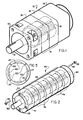
- Motor 10 comprises an end cap 12 on one end and an accessory housing 13 on the other end. Centrally disposed between end cap 12 and accessory housing 13 is a tubular frame 14 comprising two frame modules 15 according to the present invention. An armature 18 is mounted on a shaft 19 for rotation within motor 10.
- Each frame module 15 is identical. While a motor having two frame modules 15 is shown in Figure 1, a motor of any desired length can be constructed by using an appropriate number of modules 15.
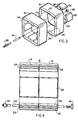
- module 15 illustrated in Figures 1 and 3 is substantially square in cross-section.
- a recessed seat 20 is formed into each of the four inner walls of the frame module 15 resulting in the walls along the extent of the seats 20 being of reduced cross-sectional thickness.
- a permanent magnet 22 is matingly adhered to each of the seats 20. Therefore, each of the modules 15 and attached sets of magnets 22 defines an individual stator assembly.
- the modules 15 may be connected together in any suitable fashion.
- a bolt hole 25 is provided through the walls of each module 15.
- the modules 15 as well as the end cap 12 and the accessory housing 13 are matingly aligned and a bolt 26 is threaded to receive a matingly threaded nut 28.
- each of the magnets is slightly shorter than the overall length of each of the modules 15.
- the magnets 22 are centered within each seat 20 so that a very slight space is left between the magnet 22 and each edge of module 15. Therefore, the magnets 22 do not interfere with the proper alignment of the modules 15 together to form the frame 14.
- the slight space left between magnets 22 and adjacent modules 15 is so small that the power of the motor and the magnet flux linkages is not affected.
- FIG. 2 shows an alternative embodiment of the invention, illustrating that any number of modules can be connected together to form a suitably sized motor frame and that the modules themselves may take different shapes.
- a motor is shown and designated generally by broad reference numeral 40.
- Motor 40 comprises an end cap 41 on one end and accessory housing 42 on the other end.
- a tubular motor frame 44 is centrally disposed between the end cap 41 and accessory housing 42 and comprises 6 frame modules 46 according to the present invention.
- each frame module 46 is circular in cross-section.
- recessed seats 47 are formed into the inner walls of each module 46 and are adapted to be fitted with an arcuate permanent magnet 49.
- each magnet 49 has a convex side for being adhered against one of the seats 47 and a concave side for facing into a centrally disposed bore defined by the inner walls of module 46.
- magnets 49 are slightly shorter than the length of each module 46 so that a narrow space is present between magnets 49 of adjacent modules 46.
- modules 46 may be secured together by any number of suitable means, they are preferably connected by means of matingly aligned holes 50 ( Figure 5) through which a suitably sized threaded bolt is passed. Each bolt 52 is threaded on each end to receive a matingly threaded nut 53.
- Constructing motor frames of the modules disclosed above substantially reduces manufacturing expenses, since numerous different lengths of motors can be constructed from a single sized module.
- Manufacturing time is also reduced since the correct size of-module for any given diameter motor will always be in stock. Permanent magnet inventories are also simplified since each module in a given diameter will use the same magents without regard to the ultimate length of the motor.
Landscapes
- Engineering & Computer Science (AREA)
- Power Engineering (AREA)
- Permanent Field Magnets Of Synchronous Machinery (AREA)
- Dc Machiner (AREA)
Applications Claiming Priority (2)
| Application Number | Priority Date | Filing Date | Title |
|---|---|---|---|
| US06/413,867 US4529902A (en) | 1982-09-01 | 1982-09-01 | Frame module for forming tubular frame of permanent magnet direct current motor |
| US413867 | 1982-09-01 |
Publications (2)
| Publication Number | Publication Date |
|---|---|
| EP0103979A1 true EP0103979A1 (de) | 1984-03-28 |
| EP0103979B1 EP0103979B1 (de) | 1987-11-11 |
Family
ID=23638997
Family Applications (1)
| Application Number | Title | Priority Date | Filing Date |
|---|---|---|---|
| EP83304707A Expired EP0103979B1 (de) | 1982-09-01 | 1983-08-15 | Gestellbaustein zur Gestaltung eines röhrenförmigen Gehäuses einer Gleichstrommaschine mit Dauermagneten |
Country Status (8)
| Country | Link |
|---|---|
| US (1) | US4529902A (de) |
| EP (1) | EP0103979B1 (de) |
| JP (1) | JPS5950762A (de) |
| CA (1) | CA1202661A (de) |
| CH (1) | CH664241A5 (de) |
| DE (1) | DE3374501D1 (de) |
| GB (1) | GB2126432B (de) |
| IL (1) | IL69493A0 (de) |
Cited By (3)
| Publication number | Priority date | Publication date | Assignee | Title |
|---|---|---|---|---|
| DE3544531A1 (de) * | 1985-12-17 | 1987-06-19 | Yi Chae Chung | Elektrische maschine |
| AU616511B2 (en) * | 1988-04-29 | 1991-10-31 | Dynamic Systems International Inc. | Electric motor |
| DE20318344U1 (de) * | 2003-11-25 | 2004-12-23 | Minebea Co., Ltd. | Motorgehäuse für einen Elektromotor |
Families Citing this family (9)
| Publication number | Priority date | Publication date | Assignee | Title |
|---|---|---|---|---|
| JPH0526759Y2 (de) * | 1987-05-29 | 1993-07-07 | ||
| US5203071A (en) * | 1990-11-05 | 1993-04-20 | Ryobi Motor Products Corp. | Method of motor construction |
| US5710474A (en) * | 1995-06-26 | 1998-01-20 | Cleveland Machine Controls | Brushless DC motor |
| DE19643301A1 (de) * | 1996-10-21 | 1998-04-23 | Maico Elektroapparate | Ventilator-Elektromotor mit umgestaltbarem Gehäuse |
| US20060192453A1 (en) * | 2003-05-27 | 2006-08-31 | Gieras Jacek F | Modular transverse flux motor with integrated brake |
| US8680730B2 (en) * | 2010-07-01 | 2014-03-25 | Powertec Industrial Motors, Inc. | Low voltage high horsepower brushless motor assembly |
| GB2520516B (en) * | 2013-11-21 | 2021-08-25 | Time To Act Ltd | Direct drive generator for renewable energy applications |
| GB2532478B (en) * | 2014-11-20 | 2021-08-25 | Time To Act Ltd | Generator |
| US10122224B2 (en) | 2015-12-28 | 2018-11-06 | Filip Sammak | Electric motor assembly |
Citations (5)
| Publication number | Priority date | Publication date | Assignee | Title |
|---|---|---|---|---|
| US2006172A (en) * | 1932-04-04 | 1935-06-25 | Ali F Klappauf | Electric machine |
| US3249780A (en) * | 1965-05-13 | 1966-05-03 | Vernitron Corp | D. c. motor with permanent magnet stator |
| DE7007623U (de) * | 1970-03-03 | 1971-11-04 | Deutsche Edelstahlwerke Ag | Dauermagnetsystem als stator fuer elektrische kleinmaschinen. |
| DD112040A1 (de) * | 1974-06-10 | 1975-03-12 | ||
| DE2738175B1 (de) * | 1977-08-24 | 1978-07-27 | Siemens Ag | Dauermagneterregte elektrische Maschine |
Family Cites Families (4)
| Publication number | Priority date | Publication date | Assignee | Title |
|---|---|---|---|---|
| US2864964A (en) * | 1955-10-03 | 1958-12-16 | Tkm Electric Corp | Multiple generator unit |
| US4211945A (en) * | 1977-10-20 | 1980-07-08 | Gen-Tech, Inc. | Multi-voltage and multi-frequency alternator/generator of modular construction |
| US4233532A (en) * | 1978-07-10 | 1980-11-11 | Esters Ernie B | Modular dynamoelectric machine |
| US4358693A (en) * | 1981-06-15 | 1982-11-09 | Charles L. Palmer | Permanent magnet motor |
-
1982
- 1982-09-01 US US06/413,867 patent/US4529902A/en not_active Expired - Fee Related
-
1983
- 1983-07-29 CA CA000433624A patent/CA1202661A/en not_active Expired
- 1983-08-15 EP EP83304707A patent/EP0103979B1/de not_active Expired
- 1983-08-15 JP JP58148179A patent/JPS5950762A/ja active Pending
- 1983-08-15 DE DE8383304707T patent/DE3374501D1/de not_active Expired
- 1983-08-15 GB GB08321882A patent/GB2126432B/en not_active Expired
- 1983-08-15 IL IL69493A patent/IL69493A0/xx unknown
- 1983-08-18 CH CH4518/83A patent/CH664241A5/de not_active IP Right Cessation
Patent Citations (5)
| Publication number | Priority date | Publication date | Assignee | Title |
|---|---|---|---|---|
| US2006172A (en) * | 1932-04-04 | 1935-06-25 | Ali F Klappauf | Electric machine |
| US3249780A (en) * | 1965-05-13 | 1966-05-03 | Vernitron Corp | D. c. motor with permanent magnet stator |
| DE7007623U (de) * | 1970-03-03 | 1971-11-04 | Deutsche Edelstahlwerke Ag | Dauermagnetsystem als stator fuer elektrische kleinmaschinen. |
| DD112040A1 (de) * | 1974-06-10 | 1975-03-12 | ||
| DE2738175B1 (de) * | 1977-08-24 | 1978-07-27 | Siemens Ag | Dauermagneterregte elektrische Maschine |
Cited By (3)
| Publication number | Priority date | Publication date | Assignee | Title |
|---|---|---|---|---|
| DE3544531A1 (de) * | 1985-12-17 | 1987-06-19 | Yi Chae Chung | Elektrische maschine |
| AU616511B2 (en) * | 1988-04-29 | 1991-10-31 | Dynamic Systems International Inc. | Electric motor |
| DE20318344U1 (de) * | 2003-11-25 | 2004-12-23 | Minebea Co., Ltd. | Motorgehäuse für einen Elektromotor |
Also Published As
| Publication number | Publication date |
|---|---|
| EP0103979B1 (de) | 1987-11-11 |
| GB2126432A (en) | 1984-03-21 |
| GB2126432B (en) | 1986-09-24 |
| US4529902A (en) | 1985-07-16 |
| CA1202661A (en) | 1986-04-01 |
| IL69493A0 (en) | 1983-11-30 |
| JPS5950762A (ja) | 1984-03-23 |
| CH664241A5 (de) | 1988-02-15 |
| DE3374501D1 (en) | 1987-12-17 |
| GB8321882D0 (en) | 1983-09-14 |
Similar Documents
| Publication | Publication Date | Title |
|---|---|---|
| US4529902A (en) | Frame module for forming tubular frame of permanent magnet direct current motor | |
| EP1936778B1 (de) | Zweiteiliger Stator mit Isolationskörper und Permanentmagnetrotor mit Rotorträger | |
| EP0144448B1 (de) | Herstellungsverfahren eines rotors mit dauermagnetfeld | |
| EP1613835B1 (de) | Flexibles motor-pack für kraftbetriebenes werkzeug und herstellungsverfahren dafür | |
| JPH09508520A (ja) | 永久磁石ロータを含むモータ | |
| EP0860930A2 (de) | Elektromotor für eine Pumpe oder einen Lüfter | |
| WO1997040572A1 (de) | Elektrische gleichstrom-maschine | |
| DE19838038A1 (de) | Elektrische Maschine mit einem um einen Stator rotierenden Rotor | |
| DE2800886A1 (de) | Gleichstrommotor | |
| DE69500984T2 (de) | Rotierende elektrische Maschine, insbesondere Automobil-Fahrzeug-Generator mit verbesserter elastischer Montage des Stators | |
| EP0132803B1 (de) | Verfahren zum Auswuchten von bewickelten Läufern elektrischer Maschinen | |
| DE60309778T2 (de) | Elektronisch kommutierter Motor | |
| DE3122655A1 (de) | "istwertgeber-vorrichtung" | |
| EP0918944B1 (de) | Distanzhülse | |
| DE3820857A1 (de) | Durch einen elektromotor angetriebener luefter | |
| DE102015226720A1 (de) | Elektrische Maschine | |
| DE10146967A1 (de) | Kühlgebläsestruktur | |
| AU3381189A (en) | Electric motor | |
| EP1648074A2 (de) | Elektrische Maschine, insbesondere Gleichstrommotor | |
| US3903443A (en) | Electric motor construction | |
| US3361914A (en) | Plastic support for motors | |
| EP1524751B1 (de) | Bürstenloser Elektromotor | |
| DE69021028T2 (de) | Gehäuseaufbau für elektrische Motoren. | |
| US3426227A (en) | Motor field mounting | |
| DE112015006209T5 (de) | Drehelektromaschine |
Legal Events
| Date | Code | Title | Description |
|---|---|---|---|
| PUAI | Public reference made under article 153(3) epc to a published international application that has entered the european phase |
Free format text: ORIGINAL CODE: 0009012 |
|
| AK | Designated contracting states |
Designated state(s): DE FR IT SE |
|
| 17P | Request for examination filed |
Effective date: 19840821 |
|
| GRAA | (expected) grant |
Free format text: ORIGINAL CODE: 0009210 |
|
| AK | Designated contracting states |
Kind code of ref document: B1 Designated state(s): DE FR IT SE |
|
| PG25 | Lapsed in a contracting state [announced via postgrant information from national office to epo] |
Ref country code: IT Free format text: LAPSE BECAUSE OF FAILURE TO SUBMIT A TRANSLATION OF THE DESCRIPTION OR TO PAY THE FEE WITHIN THE PRESCRIBED TIME-LIMIT;WARNING: LAPSES OF ITALIAN PATENTS WITH EFFECTIVE DATE BEFORE 2007 MAY HAVE OCCURRED AT ANY TIME BEFORE 2007. THE CORRECT EFFECTIVE DATE MAY BE DIFFERENT FROM THE ONE RECORDED. Effective date: 19871111 Ref country code: FR Free format text: THE PATENT HAS BEEN ANNULLED BY A DECISION OF A NATIONAL AUTHORITY Effective date: 19871111 |
|
| PG25 | Lapsed in a contracting state [announced via postgrant information from national office to epo] |
Ref country code: SE Effective date: 19871130 |
|
| REF | Corresponds to: |
Ref document number: 3374501 Country of ref document: DE Date of ref document: 19871217 |
|
| EN | Fr: translation not filed | ||
| PLBE | No opposition filed within time limit |
Free format text: ORIGINAL CODE: 0009261 |
|
| STAA | Information on the status of an ep patent application or granted ep patent |
Free format text: STATUS: NO OPPOSITION FILED WITHIN TIME LIMIT |
|
| 26N | No opposition filed | ||
| PG25 | Lapsed in a contracting state [announced via postgrant information from national office to epo] |
Ref country code: DE Effective date: 19890503 |