EP0103734B1 - Body structure of automotive vehicle having front swinging door and rear sliding door and having no pillar between front and rear doors - Google Patents
Body structure of automotive vehicle having front swinging door and rear sliding door and having no pillar between front and rear doors Download PDFInfo
- Publication number
- EP0103734B1 EP0103734B1 EP83107913A EP83107913A EP0103734B1 EP 0103734 B1 EP0103734 B1 EP 0103734B1 EP 83107913 A EP83107913 A EP 83107913A EP 83107913 A EP83107913 A EP 83107913A EP 0103734 B1 EP0103734 B1 EP 0103734B1
- Authority
- EP
- European Patent Office
- Prior art keywords
- door
- body structure
- lock
- sliding door
- rear sliding
- Prior art date
- Legal status (The legal status is an assumption and is not a legal conclusion. Google has not performed a legal analysis and makes no representation as to the accuracy of the status listed.)
- Expired
Links
Images


Classifications
-
- B—PERFORMING OPERATIONS; TRANSPORTING
- B60—VEHICLES IN GENERAL
- B60J—WINDOWS, WINDSCREENS, NON-FIXED ROOFS, DOORS, OR SIMILAR DEVICES FOR VEHICLES; REMOVABLE EXTERNAL PROTECTIVE COVERINGS SPECIALLY ADAPTED FOR VEHICLES
- B60J5/00—Doors
- B60J5/04—Doors arranged at the vehicle sides
- B60J5/0401—Upper door structure
- B60J5/0409—Upper door structure mechanism preventing outward displacement of window frame at high speeds
-
- B—PERFORMING OPERATIONS; TRANSPORTING
- B60—VEHICLES IN GENERAL
- B60J—WINDOWS, WINDSCREENS, NON-FIXED ROOFS, DOORS, OR SIMILAR DEVICES FOR VEHICLES; REMOVABLE EXTERNAL PROTECTIVE COVERINGS SPECIALLY ADAPTED FOR VEHICLES
- B60J5/00—Doors
- B60J5/04—Doors arranged at the vehicle sides
- B60J5/047—Doors arranged at the vehicle sides characterised by the opening or closing movement
- B60J5/0477—Doors arranged at the vehicle sides characterised by the opening or closing movement with two doors opening in opposite direction
- B60J5/0479—Doors arranged at the vehicle sides characterised by the opening or closing movement with two doors opening in opposite direction without B-pillar or releasable B-pillar, i.e. the pillar is moving with door
-
- B—PERFORMING OPERATIONS; TRANSPORTING
- B60—VEHICLES IN GENERAL
- B60J—WINDOWS, WINDSCREENS, NON-FIXED ROOFS, DOORS, OR SIMILAR DEVICES FOR VEHICLES; REMOVABLE EXTERNAL PROTECTIVE COVERINGS SPECIALLY ADAPTED FOR VEHICLES
- B60J5/00—Doors
- B60J5/04—Doors arranged at the vehicle sides
- B60J5/06—Doors arranged at the vehicle sides slidable; foldable
-
- Y—GENERAL TAGGING OF NEW TECHNOLOGICAL DEVELOPMENTS; GENERAL TAGGING OF CROSS-SECTIONAL TECHNOLOGIES SPANNING OVER SEVERAL SECTIONS OF THE IPC; TECHNICAL SUBJECTS COVERED BY FORMER USPC CROSS-REFERENCE ART COLLECTIONS [XRACs] AND DIGESTS
- Y10—TECHNICAL SUBJECTS COVERED BY FORMER USPC
- Y10T—TECHNICAL SUBJECTS COVERED BY FORMER US CLASSIFICATION
- Y10T292/00—Closure fasteners
- Y10T292/08—Bolts
- Y10T292/0801—Multiple
- Y10T292/0834—Sliding
- Y10T292/0836—Operating means
- Y10T292/0839—Link and lever
-
- Y—GENERAL TAGGING OF NEW TECHNOLOGICAL DEVELOPMENTS; GENERAL TAGGING OF CROSS-SECTIONAL TECHNOLOGIES SPANNING OVER SEVERAL SECTIONS OF THE IPC; TECHNICAL SUBJECTS COVERED BY FORMER USPC CROSS-REFERENCE ART COLLECTIONS [XRACs] AND DIGESTS
- Y10—TECHNICAL SUBJECTS COVERED BY FORMER USPC
- Y10T—TECHNICAL SUBJECTS COVERED BY FORMER US CLASSIFICATION
- Y10T292/00—Closure fasteners
- Y10T292/08—Bolts
- Y10T292/0801—Multiple
- Y10T292/0848—Swinging
- Y10T292/0849—Operating means
- Y10T292/0853—Link and lever
-
- Y—GENERAL TAGGING OF NEW TECHNOLOGICAL DEVELOPMENTS; GENERAL TAGGING OF CROSS-SECTIONAL TECHNOLOGIES SPANNING OVER SEVERAL SECTIONS OF THE IPC; TECHNICAL SUBJECTS COVERED BY FORMER USPC CROSS-REFERENCE ART COLLECTIONS [XRACs] AND DIGESTS
- Y10—TECHNICAL SUBJECTS COVERED BY FORMER USPC
- Y10T—TECHNICAL SUBJECTS COVERED BY FORMER US CLASSIFICATION
- Y10T292/00—Closure fasteners
- Y10T292/54—Trippers
- Y10T292/564—Swinging bolt, swinging detent
Definitions
- the present invention relates to a body structure of an automotive vehicle comprising a vehicle body defining a single door opening on each of the two longer sides thereof, a floor assembly constituting part of said vehicle body, a front swinging door hinged onto the front edge of the door opening and adapted to close the front moiety of said door opening, and a rear sliding door suspended from a guide rail for sliding movement between open and close positions, said rear sliding door adapted to close the rear moiety of said door opening when in its closed position.
- Such a center-pillarless vehicle body structure is disclosed in JP-U-54-45420, which particularly deals with a door sealing structure arranged between the front and rear doors which, on each side, oppose each other without a pillar therebetween.
- An improved guide rail structure for an automotive sliding door has already been proposed by the non-prepublished EP-A-0 100 455 which discloses an automotive vehicle having a center-pillarless body construction.
- the guide rail reinforces a side frame portion of the vehicle body, respectively, including lower side sills which form part of a floor assembly,
- further increased rigidity of the floor plate is desirable, without reducing the space of the passenger's compartment, thus'providing an improved stiffness of the vehicle body.
- the body structure incorporates the features according to the characterising portion of claim 1.
- the body structure comprises a floor assembly having a substantially flat upper surface which constitutes a flat vehicle floor, said floor assembly is supported by a lower frame work including side sills and a plurality of cross members, the lateral ends of which are secured to said side sills.
- the lower guide rails are rigidly secured to the outer periphery of the side sills, respectively, forming reinforcement of said side sills in order to provide ample resistance to bending stresses applied from above.
- a vehicle has a door opening 10 at each side thereof, which extends between a front pillar 12 and a rear pillar 14.
- a front swinging door 16 is hinged to the front vertical edge of the door opening 10 in a per se well-known manner.
- the front door 16 is adapted to close the front moiety of the door opening 10.
- a rear sliding door 18 is suspended from upper, lower and waist guide rails 20, 22 and 24 by means of engagement of slider assemblies thereto.
- the rear sliding door 18 is adapted to close the rear moiety of the door opening.
- the front swinging door 16 and the rear sliding door 18 are adapted to oppose each other at rear and front edges thereof. As will be seen from the drawings, no pillar (center-pillar) is provided between the rear edge of the front swinging door 16 and the front edge of the rear sliding door 18.
- Front, second and rear seats 26, 28 and 30 are arranged within a vehicle compartment.
- the front seat 26 comprises a driver's seat 32 and front passenger's seat 34 for two occupants.
- the driver's seat 32 and front passenger's seat 34 are separate and movable independently.
- the second seat 28 comprises a stationary seat 36 and a folding seat 38.
- the stationary seat 36 is adapted for two occupants and the folding seat 38 is adapted for one occupant.
- the corners of the second and rear seats 28 and 30 are rounded.
- the upper guide rail 20 extends substantially along a roof side rail 40 and has a front end which curves inwardly and extends through an opening in the roof side rail 40.
- the lower guide rail 22 extends along a side sill 42 and has an inwardly curving front end portion extending through an opening in the side sill.
- the waist guide rail 24 extends along essentially the entire length of the rear fender.
- upper and lower door strikers 44 and 46 are secured respectively onto the roof side rail 40 and the side sill 42.
- the upper and lower door strikers 44 and 46 are adapted to engage with upper and lower door locks of the front swinging door.
- a rear door striker 48 is secured onto the rear pillar 14 for engagement with a rear door lock of the rear sliding door.
- the upper and lower guide rails 20 and 22 secured to the roof side rail 40 and the side sill 42 respectively serve not only to allow sliding movement of the sliding door 18 but also as reinforcements of the roof side rail and the side sill to facilitate center-pillarless body structure of the vehicle with sufficient resistance to bending stresses.
- a vehicle floor assembly 50 of the vehicle is illustrated.
- the rear edge of a vehicle floor front panel 52 is joined to the front edge of a floor rear panel 54.
- Both of the front and rear panels 52 and 54 are essentially flat so as to form an essentially flat floor for the vehicle.
- the front edge of the floor front panel 52 is connected to a dash panel 56 and the rear edge of the floor rear panel 54 is connected to a rear end panel 58.
- Lateral edges of the floor front and rear panels 52 and 54 are fixedly secured to the side sills 42 and supported thereby.
- the front edge of the floor front panel 52 is supported by a front suspension cross-member 60.
- the floor rear panel 54 is supported by a rear suspension cross-member 62 near its front edge.
- a plurality of auxiliary cross-members 64, 66, 68, 70 and 72 extend laterally between the side sills 42 on both lateral sides to support the assembled floor front and rear panels 52 and 54.
- the dash panel 56 is associated with a cowling assembly 74.
- An engine compartment 76 for housing an engine and associated equipment is defined forward of the dash panel 56.
- the side sills 42 have box-shaped cross-sections defined by side sill inner and outer members 78 and 80 fixed to each other at their upper and lower edges.
- the side sill inner member 78 is formed with a stepped upper horizontal surface 82 on which the lateral edge of the floor front and rear panels 52 and 54 are mounted.
- the side sill outer member 80 is also formed with a longitudinally extending step 84 supporting the lower guide rail 22 which has a channel-shaped cross-section.
- the cross-members supporting the assembled floor front and rear panels 52 and 54 are fixed to the side sill inner members 78 by way of welding or other appropriate processes which are per se well-known.
- Figs. 8 and 9 show a front swinging door structure in detail.
- the front edge of the front swinging door 16 is attached by a pair of hinge assemblies 86 to the lower portion of the front pillar 12.
- upper and lower door locks 88 and 90 are provided at the respective upper and lower rear corners of the front swinging door 16.
- the upper door lock 88 is disposed in the upper rear corner of the front swinging door 16 so as to be engageable with the upper door striker 44 rigidly mounted on the roof side rail 40.
- the lower door lock 90 is engageable with the lower striker 46 rigidly mounted on the side sill 42.
- the front swinging door 16 is further provided with a central lock operating assembly 92.
- This assembly is operatively connected with the upper door lock 88 via a rod 94 and with the lower door lock 90 via a rod 96.
- An interior door handle 98 is located in a suitable location on the inner surface of the front swinging door 16, while an outside door handle 100 is suitably positioned on the exterior thereof.
- the assembly 92 is interconnected with the inside handle 98 by means of a rod 102 and with the outside handle 100 by means of a rod 104.
- the operation assembly 92 releases the upper door lock 88 and lower door lock 90 simultaneously from the upper striker 44 and lower striker 46, respectively.
- a key operable lock cylinder (not shown) is located in a suitable position within the front swinging door 16, while a locking/unlocking knob 106 is adapted to protrude from a location at the base of the door window.
- the operating assembly 92 is operatively connected to the lock cylinder by means of a rod (not shown) and with the knob 106 via a rod 108.
- the upper door lock 88 includes a base plate 110 having a generally U-shaped configuration as seen in plan, which is -rigidly mounted on the front swinging door 16.
- a latch member 112 is pivotally mounted on the base plate 110 by means of a pin 114 so as to engage the outboard end of the upper striker 44, which is secured to an outer member 116 of the roof side rail 40, and which is generally U-shaped as seen in plan.
- a pawl member 118 is pivotally mounted on the base plate 110 by means of a pin 120. This member functions to prevent the latch member 112 from pivotting after the latter has engaged the upper striker 44 after the door is closed.
- a lever 122 is pivotable about a pin 124 mounted on the base plate 110.
- the upper end of the rod 94 is anchored to the lever 122 such that, when the rod 94 is drawn downwardly, the lever 122 causes the pawl member 118 to undergo clockwise rotation (as seen in Fig. 10), thus releasing the pawl member 118 from the latch member 112.
- the upper door lock 88 is arranged such that, when the front swinging door 16 is closed, the rod 94 does not follow the movement of the latch member 112 and remains stationary.
- the latch member 112 is constantly biased clockwise by a helical spring (not shown) or any suitable biasing means while the pawl member 118 is constantly biased counterclockwise by a helical spring (not shown) or any other suitable biasing means.
- the lower door lock 90 includes a box-shaped cover 124 and a base 136.
- a latch 126 is secured to the cover 124 and a base 136 for pivotal movement about a pivot pin 128 protruding from the base 124.
- a pawl 130 is cooperative with the latch 126 and pivotable about a pivot pin 132.
- The_pawl 130 is adapted to engage with the latch 126.
- a lever 134 pivotably mounted onto a bracket 135 extending from the cover 124 and the base 136 via a pivot pin 137.
- the lever 134 is connected to the rod 96 and is co-operatively connected to the pawl 130 for operating the latter according to the operation of the central door lock assembly 92.
- the lower door lock 90 is rigidly secured onto the lower edge ofthefront door inner panel 16.
- the base 136 has an opening 138 through which the lower door striker 46, having a generally U-shaped front elevation, can enter.
- the pawl 130 is adapted to prevent the rotation of the latch 126 ' once the latter engages the lower striker 46.
- the lever 134 is adapted to cause the pawl to rotate counterclockwise (as seen in Fig. 12) when the rod 96 is drawn upwardly. This disengages the latch 126 from the lower striker 46 to permit the front swinging door 16 to open.
- the latch 126 may be biased clockwise by means of a suitable biasing means such as helical spring, while the pawl 130 and the pin 132 may be biased counterclockwise by means of a biasing means such as a helical spring.
- the lock operating assembly 92 includes a base plate 139 rigidly secured to the front swinging door 16. At the upper portion of the base plate 139, a release lever 140 is pivotally mounted on a pin 142 which is perpendicularto the general plane of the base plate 139. It should be noted at this time, that all the pins referred to hereinafter are also perpendicular to the general plane of the base plate 139.
- a helical spring 144 is wound around the pin 142 and one end 146 thereof is anchored to the pin 142.
- the other end 148 of this spring is anchored to a lug 150 which extends forwardly from the left edge of the release lever 140 at a location below the pin 142.
- the spring 152 thus yieldably urges the release lever 140 counterclockwise to its inoperative position shown in Fig. 13, in which a lug 154 projecting from the lower end of the release lever 140 abuts a first stop 156.
- This stop 156 delimits the right end of an arcuate notch 158 which lies near the center of the base plate 139.
- the release lever 140 is formed with an arcuate slot 160 whose center of curvature coincides with the axis of the pin 142.
- a pin 162 slidable in and along the arcuate slot 160 is fixed to one end of the rod 102, the other end of which, as previously described, is operatively connected to the interior door handle 98. Pulling the rod 102 to the left as seen in the drawings will move the release lever 140 to its operative position, in which the lug 154 abuts a second stop 164. This second stop delimits the left end of the notch 158.
- the rod 104 operatively connected with the exterior door handle 100 is formed with a stepped portion which passes through an aperture in which an elastomeric grommet 165 is disposed and which is formed in a lug 166 formed on the release lever 140. In this arrangement, urging the rod downwardly will also move the release lever 140 to the operative position.
- An arm 168 extends to the left from an upper portion of the release lever 140 and has a sublever 170 rotatably mounted on the free end thereof by means of a pin 172.
- the lower end of the sublever 170 is formed so as to have a generally "J" shape which terminates at an engaging _section 174.
- This engaging section 174 is formed by bending the end of the sublever 170 to the rear (as seen in the drawings).
- An abutment 176 extends forwardly from the right edge of an intermediate portion of the sublever 170. This abutment is located such that when the release lever 140 is in its operative position the abutment lies in the path of rotation of a hook-shaped end or engaging section 178 of a second connecting lever 180, which will be described in detail later, while in the operative position of the release lever 140, it is raised upwardly out of the path of rotation mentioned above.
- the sublever 170 is formed with a slot 182 in the intermediate portion thereof.
- a locking lever 184 is rotatably mounted on an intermediate part of the base plate 139 by means of a pin 186.
- a pin 188 is studded on the lever 184 above the pin 186 and slidably engaged in the slot 182.
- the locking lever 184 is operatively connected to an overcenter or two position snap action spring 192 so as to be biased toward either one of two positions. This spring is retained at one end by the base plate 139 and at the other end by the lever 184.
- a rearwardly oriented lug 194 formed at the right end of the lever 184 abuts a first stop 196 formed in a curved edge of an intermediate portion of the base plate 139, whereas in the locked position the lug 194 abut a second stop 198 formed in a curved edge of the base plate 139 which faces the above-mentioned edge from above.
- the lever 184 is connected at its left end to the lower end of the rod 108 which, as previously described, is connected to the lock button or knob 106, and at its right end to the rod 105 which in turn is connected to the lock cylinder.
- the lever 184 is thus movable to the locked or unlocked position when either one of the knob 106 or the lock cylinder is operated and maintained in the selected position under the influence of the spring 192.
- the sublever 170 when the lever 184 assumes its unlocked position, the sublever 170 also assumes an engaged position as shown in Fig. 13. With levers 184,170 in these positions the engaging section 174 is engageable with an abutment 200 of a first connecting lever 202 which will be described later. However, upon the lever 184 assuming its locked position the sublever 170 assumes a position in which the engaging section 174 is no longer engageable with the abutment 200.
- the sublever 170 when the sublever 170 is in its engaged position it can be raised by moving the release lever 140 to the operative position so that the abutment 200 is engaged by and moved upward by the engaging section 174, thus rotating the first connecting lever 202.
- the engaging section 174 misses the first connecting lever 202 despite the movement of the release lever 140 into the operative position.
- the first and second connecting levers 202 and 180 are pivotally mounted on a lower part of the base plate 139 by means of a common pin 204.
- a helical spring 206 is wound around the pin 204 and anchored at one end to same. The other end of the spring 206 is anchored to a forwardly directed lug 208 formed on the lower edge of the first connecting lever 202.
- the first connecting lever 202 Under the bias of the spring 206, the first connecting lever 202 normally remains in an inoperative position, in which a lug 210 formed on the right upper edge of the lever 202 and about which an elastomeric cushioning member 212 is disposed, abuts against a forwardly directed stop 214formed on the base plate 139.
- the first connecting lever 202 is formed with the previously mentioned abutment 200 at its leftmost end white retaining the lower end of the rod 94 at its rightmost end, the latter mentioned rod 94 providing an operative connection with the upper door lock 88 as previously described.
- a pair of lugs 218 and 220 project from the right upper end and right lower end of the second connecting lever 180, respectively.
- a coil tension spring 222 is retained at one end by the lower lug 220 of the lever 180 and at the other by stop 214 of the base plate 139.
- the lever 180 is biased counterclockwise by the spring 222 to normally assume an inoperative position shown in Fig. 13, in which the upper lug 218 remains in contact with the cushioning lever 202.
- the second connecting lever 180 is connected to the rod 96 (operatively connected to the lower door lock 90) at its left end and formed at the upper extension thereof with the hook-shaped end 178 previously mentioned.
- the lever 180 Due to the engagement of the lug 218 with the lever 202, the lever 180 is rotated to the operative position in synchronism with the lever 202 from its inoperative position to the its operative position, thus pulling the rod 96 upwardly to release the lower door lock 90.
- the second connecting lever 180 is movable to its operative position independently of the first connecting lever 202 as already discussed and as shown, when the rod 96 is raised temporarily via the interconnection with the latch 126 in the lower door lock 90 during the closing of the front swinging door 16.
- the hook-shaped end 178 of the lever 180 will engage with the abutment 176 to cause the sublever 170 to return to its engaged position. This induces a simultaneous movement of the locking lever 184 from its locked position to its unlocked position.
- both the lever 184 and sublever 170 are maintained in their locked and released positions respectively and the rod 96 rises and moves the second connecting lever 180 to its operative position.
- the abutment 176 has then been raised by the release lever 140 out of the path of the engaging section 178, and the sublever 170 maintains its released position.
- a window pane 230 is associated with front and rear lower sashes 232 and 234 for up/down movement therealong.
- a window regulator 236 with a regulator handle 238 is associated with the window pane 230 for up/ down movement of the latter.
- a door check 240 is installed on the front edge of the front swinging door 16 for detecting the open position thereof.
- a glass-run seal 242 extends along the door sash 12 and is engageable with the circumferential edge of the window pane 230 for guiding up/down movement thereof.
- a weatherstrip 380 is equipped along the rear edge of the front swinging door 16 and a rubber seal 246 is attached along the lower edge of the door.
- Fig. 14 shows the detailed structure of the rear sliding door 18.
- the rear sliding door 18 is provided with upper and lower slider assemblies 250 and 252 respectively near its upper and lower front corners.
- a waist slider assembly 254 shown in more detail in Fig. 15 is also provided on the rear sliding door near its rear edge.
- the slider assembly 254 has a pair of horizontal rollers 256 rotatably mounted on vertical rotational axles projecting from a guide shoe 260 and a vertical roller 258 rotatably mounted on a horizontal axle projecting from the guide shoe.
- the upper and lower slider assemblies 250 and 252 are of the same structure .as that of the waist slider assembly 254.
- Each of the rollers 256 and 258 is adapted to engage the waist guide rail 24 for sliding movement therealong.
- the waist slider assembly has the guide shoe 260 pivotably secured to the rear sliding door for pivotal movement about a pivot 262. This allows the rear sliding door 18 to conform as closely as possible to the contours of the vehicle exterior as the door is opened and closed, as illustrated by comparison of the door positions drawn in solid and phantom lines in Fig. 16.
- the rear sliding door 18 is provided with the rear door lock 264 near its rear edge.
- the rear door lock 264 is connected to a door lock operating assembly 266 by way of a rod 268, bell crank 270 and a second rod 272.
- the door lock operating assembly 266 is also connected to a door lock knob 274 via a rod 276 for locking and unlocking the door lock operating assembly.
- a child safety lock 278 is associated with the door lock operating assembly 266.
- a door inside handle 284 is connected to the door lock operating assembly 266 by means of a rod (not shown) and a door outside handle 288 is connected to the latter by means of a rod (not shown).
- the door lock 264 includes a box-shaped base 290.
- a latch 292 is pivotably installed within the base and pivotable about a pivot pin 294 protruding from the base.
- a pawl member 296 is also pivotably supported by the base and co-operates with the latch 292.
- the pawl member 296 is connected to the door lock operating assembly 266 via the rods 268, 272 and the bell crank 270.
- a wedge-shaped member 298 with a rod 300 is provided within the base.
- a tension spring 302 encircles the rod 300 in order to bias the wedge-shaped member 298 toward right in Fig. 17. This wedge-shaped member 298 is adapted to contact with the rear door striker 48, when the door is closed to damp the movement of the rear door striker and so prevent noises due to vibration.
- the latch 292 is engageable with the striker 48 when the sliding door is closed.
- the pawl member 296 engages the latch 292 to retain- the latter in its latching position.
- the pawl member 296 is rotated counterclockwise in Fig. 17 via the door lock operating assembly 266, the rod 272, the bell crank 270 and the rod 268.
- the pawl member 296 is thus released from engagement with the latch 292 to allow the latter to rotate counterclockwise.
- the striker becomes free from engagement with the recess 304 of the base 290 so as to allow the sliding door to open.
- the side sill outer member 80 is formed to have the step 84 on which the lower guide rail 22 is fixedly mounted.
- Lower guide rail 22 is of substantially channel-shaped cross-section for secure engagement with the lower slider assembly 252 of the sliding door.
- the side sill outer member 80 is formed with a substantially rectangular opening 306.
- the lower guide rail 22 curves through the rectangular opening 306 starting at a point 308 near its forward end. The front end 310 of the lower guide rail 22 is thus fully received within the closed section defined in the side sill 42.
- An essentially vertical reinforcement member 312 is inserted in the closed section of the side sill 42.
- the lower edge 318 of the vertical reinforcement member 312 is inserted between the lower flanges 314 and 316 of the side sill inner and outer members 78 and 80.
- the upper edge 320 of the vertical reinforcement member 312 is secured to the vertical section 322 of the side sill outer member 80.
- the vertical reinforcement member 312 is also provided with a substantially rectangular opening 324 through which the end portion 310 of the lower guide rail 22 extends.
- a flange 326 is extended from the edge of the rectangular opening 324 of the vertical reinforcement member 312. Likewise, flange 326 extends towards inside of the closed section of the side sill from the lower lateral edge of the rectangular opening 306.
- a horizontal reinforcement member 328 is inserted in the internal space of the side sill 42.
- the horizontal reinforcement member 328 has a substantially horizontal major portion 330 and an vertical wall portion 332 which extends from the inner edge of horizontal portion 330.
- the edge 348 of horizontal -portion 330 is fixed to the lower surface of the flange extending from the lower edge of the rectangular opening 306 in the side sill outer member 80.
- Horizontal portion 330 is also fixed to the upper surface of the flange 326 extending from the lower edge of rectangular opening 324 in vertical reinforcement member 312.
- the vertical wall portion 332 is fixed to the inner surface of the side sill inner member 78.
- a weatherstrip 380 is mounted along the rear vertical edge of the front door 16.
- a weatherstrip 424 is installed along the front vertical edge of the rear door 18.
- the longitudinal edge of the roof outer panel 360 along the roof side rail 40 is bent to form a drip- channel 362 in conjunction with a drip seal 364 fastened to its edge.
- the lateral edge of the roof outer panel 360 is supported by the roof side rail 40 to which a weatherstrip 365 is attached.
- the drip seal 364 has a lip 366 extending upwardly.
- the lip 366 is adapted to contact the upper edges 368 and 370 of the front and rear doors 16 and 18.
- the weatherstrip 365 has a portion 372 protruding outwardly.
- the portion 372 of the weatherstrip 365 is adapted to contact a portion 374 of a door innner panel 376 of the front door 16.
- the portion 372 of the weatherstrip 365 is also adapted to contact the corresponding portion of the door inner panel 378 of the rear door. Therefore, a double water-proof seal between the upper frame of the vehicle body and the upper edge portions 368 and 370 of the front and rear doors 16 and 18 is provided by the drip seal 364 and weatherstrip 366.
- the weatherstrip 380 is mounted on the vertical surface 382 of the door inner panel 376 by means of a resin fastener 384.
- the weatherstrip 380 is hollow and essentially cylindrical in cross-section, so that it defines a through opening 386 which comprises an upper smaller diameter section 388 and a lower larger diameter section 390.
- One wall 392 of the weatherstrip 380 is in contact with a flat surface 394 where the rear end of a door outer panel 396 is bent back overthe rear vertical edge of the door inner panel 376.
- Another wall 398 of the weatherstrip 380 opposes the front vertical edge of the rear door 18 in order to establish a water-proof seal therebetween when the doors are closed.
- the front door inner panel 376 and the front door outer panel 396 define an internal space. therebetween, in which a reinforcement member 400 is inserted.
- the outer panel 396 has a flange 402, and the inner panel has a flange 404 to which a flange 406 of the reinforcement member 400 is attached.
- a window weatherstrip 408 is engaged to the flanges 402, 404 and 406.
- central sections 414 of the window weatherstrip 408 engages the edges of the window pane 230.
- a garnish 418 is fastened with resin fasteners 420 to a surface 422 of the inner panel 376 facing the vehicle compartment.
- the weatherstrip 424 of the rear door 18 is installed on the front vertical surface 426 of the rear door inner panel 378.
- the weatherstrip 424 is of essentially U-shaped configuration with lip portions 428 and 430.
- the lip 430 is attached to a flange 432 of the rear door inner panel 378 which is connected to a flange 434 of an outer panel 436 of the rear door.
- a flange 438 of a reinforcement member 440 is interposed between the flange 432 and 434 of the rear door inner and outer panels 378 and 436.
- a garnish 442 is attached to the surface of the rear door inner panel 378 facing the vehicle compartment with resin fasteners 444.
- a window weatherstrip 446 is attached on the flanges 448, 450 and 452 of the inner and outer panels 378 and 436 and the reinforcement member 440.
- a windowpane 454 engages the window weatherstrip 446 in water-proofing fashion.
- the lip 428 is adapted to contact the wall 398 of the front door weatherstrip 380 in water-proofing fashion in order to establish first inner water-proof seal therebetween.
- the front end of the flange 434 of the outer panel 436 is bent to form a contact surface 456.
- the contact surface 456 of the rear door outer panel 436 contacts the wall 398 of the front door weatherstrip 380 to establish a second outer water-proof seal.
- the weatherstrip 380 has an enlarged top section 458 longitudinally expanded and of essentially rectangular cup-shaped configuration with a water spout 460 at its floor.
- the top section 458 extends above the weatherstrip 366 with the water spout 460 beneath the drip seal 364.
- the top section 458 contacts the portion 372 of the weatherstrip 366 in water-proofing fashion.
- a lip 462 extends upwardly from the top of the outside vertical wall 464 of the top section 458. The lip 462 is adapted to contact the drip seal 364 in water-proofing fashion.
- the weatherstrip 380 is formed with a recess 466 in the face opposing the front edge of the rear door 18.
- the recess 466 is adapted to engage a projection 468 protruding from an enlarged top section 470 of the weatherstrip 424 of the rear door 18.
- the top section 470 of the rear door weatherstrip 424 defines a water spout 472.
- the water spout 472 communicates with the internal space of the substantially U-shaped major portion of the weatherstrip 424 via a passageway 474 formed through the top section.
- the axis of the passageway 474 for establishing communication between the water spout 472 and the top of the U-shaped section is oblique to the longitudinal axis of the weatherstrip 424.
- the top section 316 is positioned beneath the drip seal 364 with water-proof contact provided by a lip 478 extending from the outer wall of the top section 470.
- the top section 470 also establishes water-proof contact with the portion 372 of the weatherstrip 365.
- the weatherstrip 380 and 424 cooperate so as to form two parallel sealing interfaces and simultaneously two parallel downspouts for possible leakage from the conventional vehicular rain gutter.
- the first sealing interface is the point of contact between the wall 398 of the front door weatherstrip 380 and the inboard lip 428 of the rear door weatherstrip 424.
- the second sealing interface is the point of contact between the wall 398 and the special contact surface 456 at the edge of the rear door outer panel 436.
- the preferred embodiment of the vehicle body structure according to the present invention can provide a wider passenger compartment by application of a substantially flat floor assembly.
- the center-pillariess structure of the vehicle framework in which the rear edge of the front swinging door directly opposes the front edge of the rear sliding door provides a wider portal for entering and exiting the vehicle compartment.
- the door lock mechanisms provided for the front swinging door and the rear sliding door are designed to allow the center - pillarless frame work.
- sliding door support structures are utilized to reinforce the vehicle framework so that the vehicle body is sufficient strong even without the conventional center pillar.
Landscapes
- Engineering & Computer Science (AREA)
- Mechanical Engineering (AREA)
- Body Structure For Vehicles (AREA)
Description
- The present invention relates to a body structure of an automotive vehicle comprising a vehicle body defining a single door opening on each of the two longer sides thereof, a floor assembly constituting part of said vehicle body, a front swinging door hinged onto the front edge of the door opening and adapted to close the front moiety of said door opening, and a rear sliding door suspended from a guide rail for sliding movement between open and close positions, said rear sliding door adapted to close the rear moiety of said door opening when in its closed position.
- Such a center-pillarless vehicle body structure is disclosed in JP-U-54-45420, which particularly deals with a door sealing structure arranged between the front and rear doors which, on each side, oppose each other without a pillar therebetween.
- However, difficulties have been encountered in this case with providing sufficient bending rigidity of the vehicle body's floor assembly, on the one hand, and to locate the necessary guide rails, which slidably engage slider assemblies of the rear sliding door on the other, resulting in a relatively high elevation of the vehicle floor. Thus, the door opening for the passengers to get in and out of the vehicle is disadvantageously decreased, as is the riding space available for the passengers within the vehicle compartment. Moreover, the conventional lower body structure of the vehicle includes a relatively high step for entering or leaving the vehicle compartment which is less convenient for the passengers.
- An improved guide rail structure. for an automotive sliding door has already been proposed by the non-prepublished EP-
A-0 100 455 which discloses an automotive vehicle having a center-pillarless body construction. The guide rail reinforces a side frame portion of the vehicle body, respectively, including lower side sills which form part of a floor assembly, However, further increased rigidity of the floor plate is desirable, without reducing the space of the passenger's compartment, thus'providing an improved stiffness of the vehicle body. - With these problems in mind, therefore, it is the primary object of the present invention to provide a body structure of an automotive vehicle in accordance with the precharacterising portion of claim 1 which is adapted to increase the bending rigidity of the vehicle body's floor assembly and provide a wider passenger compartment, as well as an enlarged door opening for ease of the vehicle's use.
- To achieve the above-mentioned object, the body structure incorporates the features according to the characterising portion of claim 1.
- Thus, the body structure comprises a floor assembly having a substantially flat upper surface which constitutes a flat vehicle floor, said floor assembly is supported by a lower frame work including side sills and a plurality of cross members, the lateral ends of which are secured to said side sills.
- Moreover, the lower guide rails are rigidly secured to the outer periphery of the side sills, respectively, forming reinforcement of said side sills in order to provide ample resistance to bending stresses applied from above.
- Further advantageous embodiments of the invention adapted to an automotive vehicle having a center-pillarless body construction are laid down in the subclaims.
- The present invention will be understood more fully from the following detailed description and from the accompanying drawings of the preferred embodiment of the invention, which, however, should not be taken as limiting the invention.but are for illustration and explanation only:
- In the drawings:
- Fig. 1 is a perspective view of an automotive vehicle having the preferred embodiment of a body structure according to the present invention:
- Fig. 2 is a side elevation of the vehicle of Fig. 1;
- Fig. 3 is a plan view of the vehicle of Fig. 1;
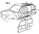
- Fig. 4 is an exploded perspective view of the vehicle, in which an engine hood and wheels are neglected and front and rear doors are released from the vehicle body;
- Fig. 5 shows a longitudinal section of a floor assembly of the vehicle of Fig. 1;
- Fig. 6 shows a cross section taken along line VI-VI of Fig. 4;
- Fig. 7 shows a cross section taken along line VII-VII of Fig. 4;
- Fig. 8 is an elevation of a front swinging door, from which the inside lining of the door has been removed so as to show the front door mechanism;
- Fig. 9 shows a section taken along line IX-IX of Fig. 8;
- Fig. 10 is a cross-sectional view of an upper door lock of the front swinging door;
- Fig. 11 is a cross-sectional view of a lower door lock of the front swinging door;
- Fig. 12 is a view taken along line XII-XII of Fig. 11;
- Fig. 13 is an enlarged elevation of a center door lock operating assembly of Fig. 8;
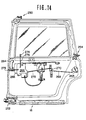
- Fig. 14 is an elevation of the rear sliding door, from which the inside lining of the door has been removed for explanation;
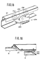
- Fig. 15 is a perspective illustration of a waist slider assembly mounted on the rear sliding door;
- Fig. 16 is a horizontal sectional view illustrating movement of the waist slider assembly of Fig. 15;
- Fig. 17 is an elevation of the door lock of the rear sliding door;
- Fig. 18 is a section taken along line XVIII-XVIII of Fig. 17;
- Fig. 19 is a perspective view of a part of a side sill of the vehicle framework, on which the lower guide rail is mounted;
- Fig. 20 shows a cross-section taken along line XX-XX of Fig. 19;
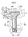
- Fig. 21 is an elevation of part of the interface structure between the front and rear doors;
- Fig. 22 shows a cross-section taken along line XXII-XXII of Fig. 21;
- Fig. 23 shows a section taken along line XXIII-XXIII of Fig. 21; and
- Fig. 24 shows a section taken along line XXIV-XXIV of Fig. 21.
- Referring now to the drawings, particularly to Figs. 1 to 4, a vehicle has a door opening 10 at each side thereof, which extends between a
front pillar 12 and arear pillar 14. A front swingingdoor 16 is hinged to the front vertical edge of the door opening 10 in a per se well-known manner. Thefront door 16 is adapted to close the front moiety of the door opening 10. A rear slidingdoor 18 is suspended from upper, lower andwaist guide rails door 18 is adapted to close the rear moiety of the door opening. The front swingingdoor 16 and the rear slidingdoor 18 are adapted to oppose each other at rear and front edges thereof. As will be seen from the drawings, no pillar (center-pillar) is provided between the rear edge of the front swingingdoor 16 and the front edge of the rear slidingdoor 18. - Front, second and
rear seats front seat 26 comprises a driver'sseat 32 and front passenger's seat 34 for two occupants. The driver'sseat 32 and front passenger's seat 34 are separate and movable independently. Thesecond seat 28 comprises astationary seat 36 and afolding seat 38. Thestationary seat 36 is adapted for two occupants and thefolding seat 38 is adapted for one occupant. The corners of the second andrear seats - As particularly shown in Fig. 4, the
upper guide rail 20 extends substantially along aroof side rail 40 and has a front end which curves inwardly and extends through an opening in theroof side rail 40. Thelower guide rail 22 extends along aside sill 42 and has an inwardly curving front end portion extending through an opening in the side sill. Thewaist guide rail 24 extends along essentially the entire length of the rear fender. Near the front ends of the upper andlower guide rails lower door strikers roof side rail 40 and theside sill 42. The upper andlower door strikers rear door striker 48 is secured onto therear pillar 14 for engagement with a rear door lock of the rear sliding door. - The upper and
lower guide rails roof side rail 40 and theside sill 42 respectively serve not only to allow sliding movement of the slidingdoor 18 but also as reinforcements of the roof side rail and the side sill to facilitate center-pillarless body structure of the vehicle with sufficient resistance to bending stresses. - The detailed structure of the vehicle body of the preferred embodiment will be described below with reference to Figs. 5 to 19 which show various parts of the vehicle bodywork.
- Referring to Figs. 5 to 7, a
vehicle floor assembly 50 of the vehicle is illustrated. The rear edge of a vehiclefloor front panel 52 is joined to the front edge of a floorrear panel 54. Both of the front andrear panels floor front panel 52 is connected to adash panel 56 and the rear edge of the floorrear panel 54 is connected to arear end panel 58. Lateral edges of the floor front andrear panels side sills 42 and supported thereby. The front edge of thefloor front panel 52 is supported by afront suspension cross-member 60. Likewise, the floorrear panel 54 is supported by arear suspension cross-member 62 near its front edge. A plurality ofauxiliary cross-members side sills 42 on both lateral sides to support the assembled floor front andrear panels - The
dash panel 56 is associated with acowling assembly 74. Anengine compartment 76 for housing an engine and associated equipment is defined forward of thedash panel 56. - As clearly seen from Figs. 6 and 7, the
side sills 42 have box-shaped cross-sections defined by side sill inner andouter members inner member 78 is formed with a stepped upperhorizontal surface 82 on which the lateral edge of the floor front andrear panels outer member 80 is also formed with alongitudinally extending step 84 supporting thelower guide rail 22 which has a channel-shaped cross-section. The cross-members supporting the assembled floor front andrear panels inner members 78 by way of welding or other appropriate processes which are per se well-known. - With the floor assembly structure as disclosed hereabove, utility space in the vehicle compartment can be significantly increased in comparison with the conventional sedan type vehicle due to the essentially flat floor of the vehicle. Furthermore, by mounting the lower guide rail onto the side of the side sill, the elevation of the vehicle floor can be lowered in comparison with the floor elevation of conventional van-type vehicles. This relatively lower floor provides a more comfortable height for the vehicle compartment and is more convenient for getting into and out of the vehicle.
- Figs. 8 and 9 show a front swinging door structure in detail. The front edge of the front swinging
door 16 is attached by a pair ofhinge assemblies 86 to the lower portion of thefront pillar 12. As set forth previously, upper and lower door locks 88 and 90 are provided at the respective upper and lower rear corners of the front swingingdoor 16. - The
upper door lock 88 is disposed in the upper rear corner of the front swingingdoor 16 so as to be engageable with theupper door striker 44 rigidly mounted on theroof side rail 40. Thelower door lock 90 is engageable with thelower striker 46 rigidly mounted on theside sill 42. - The front swinging
door 16 is further provided with a centrallock operating assembly 92. This assembly is operatively connected with theupper door lock 88 via arod 94 and with thelower door lock 90 via arod 96. - An
interior door handle 98 is located in a suitable location on the inner surface of the front swingingdoor 16, while anoutside door handle 100 is suitably positioned on the exterior thereof. Theassembly 92 is interconnected with theinside handle 98 by means of arod 102 and with theoutside handle 100 by means of arod 104. When either one of theinside handle 98 or theoutside handle 100 is manipulated to open the front swingingdoor 16, theoperation assembly 92 releases theupper door lock 88 andlower door lock 90 simultaneously from theupper striker 44 andlower striker 46, respectively. - A key operable lock cylinder (not shown) is located in a suitable position within the
front swinging door 16, while a locking/unlockingknob 106 is adapted to protrude from a location at the base of the door window. The operatingassembly 92 is operatively connected to the lock cylinder by means of a rod (not shown) and with theknob 106 via arod 108. When the lock cylinder or theknob 106 is operated to lock thefront swinging door 16, the operative connection between theinside handle 98 andoutside handle 100 and theupper door lock 88 andlower door lock 90 is cancelled. - As shown in Fig. 10, the
upper door lock 88 includes a base plate 110 having a generally U-shaped configuration as seen in plan, which is -rigidly mounted on thefront swinging door 16. Alatch member 112 is pivotally mounted on the base plate 110 by means of apin 114 so as to engage the outboard end of theupper striker 44, which is secured to anouter member 116 of theroof side rail 40, and which is generally U-shaped as seen in plan. Apawl member 118 is pivotally mounted on the base plate 110 by means of apin 120. This member functions to prevent thelatch member 112 from pivotting after the latter has engaged theupper striker 44 after the door is closed. Alever 122 is pivotable about apin 124 mounted on the base plate 110. The upper end of therod 94 is anchored to thelever 122 such that, when therod 94 is drawn downwardly, thelever 122 causes thepawl member 118 to undergo clockwise rotation (as seen in Fig. 10), thus releasing thepawl member 118 from thelatch member 112. - The
upper door lock 88, is arranged such that, when the front swingingdoor 16 is closed, therod 94 does not follow the movement of thelatch member 112 and remains stationary. Thelatch member 112 is constantly biased clockwise by a helical spring (not shown) or any suitable biasing means while thepawl member 118 is constantly biased counterclockwise by a helical spring (not shown) or any other suitable biasing means. - As shown in Figs. 11 and 12, the
lower door lock 90 includes a box-shapedcover 124 and abase 136. Alatch 126 is secured to thecover 124 and abase 136 for pivotal movement about apivot pin 128 protruding from thebase 124. Apawl 130 is cooperative with thelatch 126 and pivotable about apivot pin 132.The_pawl 130 is adapted to engage with thelatch 126. Alever 134 pivotably mounted onto abracket 135 extending from thecover 124 and thebase 136 via apivot pin 137. Thelever 134 is connected to therod 96 and is co-operatively connected to thepawl 130 for operating the latter according to the operation of the centraldoor lock assembly 92. Thelower door lock 90 is rigidly secured onto the lower edge ofthefront doorinner panel 16. - The
base 136 has anopening 138 through which thelower door striker 46, having a generally U-shaped front elevation, can enter. Thepawl 130 is adapted to prevent the rotation of thelatch 126 ' once the latter engages thelower striker 46. Thelever 134 is adapted to cause the pawl to rotate counterclockwise (as seen in Fig. 12) when therod 96 is drawn upwardly. This disengages thelatch 126 from thelower striker 46 to permit thefront swinging door 16 to open. When the front swingingdoor 16 is closed, thelower striker 46 engages thelatch 126. Thelatch 126 may be biased clockwise by means of a suitable biasing means such as helical spring, while thepawl 130 and thepin 132 may be biased counterclockwise by means of a biasing means such as a helical spring. - As shown in Fig. 13, the
lock operating assembly 92 includes abase plate 139 rigidly secured to thefront swinging door 16. At the upper portion of thebase plate 139, arelease lever 140 is pivotally mounted on apin 142 which is perpendicularto the general plane of thebase plate 139. It should be noted at this time, that all the pins referred to hereinafter are also perpendicular to the general plane of thebase plate 139. - A
helical spring 144 is wound around thepin 142 and oneend 146 thereof is anchored to thepin 142. Theother end 148 of this spring is anchored to alug 150 which extends forwardly from the left edge of therelease lever 140 at a location below thepin 142. The spring 152 thus yieldably urges therelease lever 140 counterclockwise to its inoperative position shown in Fig. 13, in which alug 154 projecting from the lower end of therelease lever 140 abuts afirst stop 156. Thisstop 156 delimits the right end of anarcuate notch 158 which lies near the center of thebase plate 139. - The
release lever 140 is formed with anarcuate slot 160 whose center of curvature coincides with the axis of thepin 142. Apin 162 slidable in and along thearcuate slot 160 is fixed to one end of therod 102, the other end of which, as previously described, is operatively connected to theinterior door handle 98. Pulling therod 102 to the left as seen in the drawings will move therelease lever 140 to its operative position, in which thelug 154 abuts asecond stop 164. This second stop delimits the left end of thenotch 158. - The
rod 104 operatively connected with theexterior door handle 100 is formed with a stepped portion which passes through an aperture in which anelastomeric grommet 165 is disposed and which is formed in alug 166 formed on therelease lever 140. In this arrangement, urging the rod downwardly will also move therelease lever 140 to the operative position. - An
arm 168 extends to the left from an upper portion of therelease lever 140 and has asublever 170 rotatably mounted on the free end thereof by means of apin 172. - The lower end of the
sublever 170 is formed so as to have a generally "J" shape which terminates at an engaging_section 174. This engagingsection 174 is formed by bending the end of thesublever 170 to the rear (as seen in the drawings). - An
abutment 176 extends forwardly from the right edge of an intermediate portion of thesublever 170. This abutment is located such that when therelease lever 140 is in its operative position the abutment lies in the path of rotation of a hook-shaped end or engagingsection 178 of a second connectinglever 180, which will be described in detail later, while in the operative position of therelease lever 140, it is raised upwardly out of the path of rotation mentioned above. - The
sublever 170 is formed with aslot 182 in the intermediate portion thereof. A lockinglever 184 is rotatably mounted on an intermediate part of thebase plate 139 by means of apin 186. Apin 188 is studded on thelever 184 above thepin 186 and slidably engaged in theslot 182. - The locking
lever 184 is operatively connected to an overcenter or two positionsnap action spring 192 so as to be biased toward either one of two positions. This spring is retained at one end by thebase plate 139 and at the other end by thelever 184. In the unlocked position of the locking lever 184 (as shown in Fig. 13) a rearwardly orientedlug 194 formed at the right end of thelever 184 abuts afirst stop 196 formed in a curved edge of an intermediate portion of thebase plate 139, whereas in the locked position thelug 194 abut asecond stop 198 formed in a curved edge of thebase plate 139 which faces the above-mentioned edge from above. - The
lever 184 is connected at its left end to the lower end of therod 108 which, as previously described, is connected to the lock button orknob 106, and at its right end to therod 105 which in turn is connected to the lock cylinder. Thelever 184 is thus movable to the locked or unlocked position when either one of theknob 106 or the lock cylinder is operated and maintained in the selected position under the influence of thespring 192. - In the above arrangement, when the
lever 184 assumes its unlocked position, thesublever 170 also assumes an engaged position as shown in Fig. 13. With levers 184,170 in these positions the engagingsection 174 is engageable with anabutment 200 of a first connectinglever 202 which will be described later. However, upon thelever 184 assuming its locked position thesublever 170 assumes a position in which the engagingsection 174 is no longer engageable with theabutment 200. - Thus, when the
sublever 170 is in its engaged position it can be raised by moving therelease lever 140 to the operative position so that theabutment 200 is engaged by and moved upward by the engagingsection 174, thus rotating the first connectinglever 202. However, in the released position of thesublever 170, the engagingsection 174 misses the first connectinglever 202 despite the movement of therelease lever 140 into the operative position. - The first and second connecting
levers base plate 139 by means of acommon pin 204. Ahelical spring 206 is wound around thepin 204 and anchored at one end to same. The other end of thespring 206 is anchored to a forwardly directedlug 208 formed on the lower edge of the first connectinglever 202. Under the bias of thespring 206, the first connectinglever 202 normally remains in an inoperative position, in which alug 210 formed on the right upper edge of thelever 202 and about which anelastomeric cushioning member 212 is disposed, abuts against a forwardly directed stop 214formed on thebase plate 139. - The first connecting
lever 202 is formed with the previously mentionedabutment 200 at its leftmost end white retaining the lower end of therod 94 at its rightmost end, the latter mentionedrod 94 providing an operative connection with theupper door lock 88 as previously described. - Thus, when the locking
lever 184 is in its unlocked position and thesublever 170 is raised, the engagingsection 174 contacts the first connectinglever 202, rotating same clockwise and thus pullingrod 94 downwards to release theupper door lock 88. - A pair of
lugs lever 180, respectively. Acoil tension spring 222 is retained at one end by thelower lug 220 of thelever 180 and at the other bystop 214 of thebase plate 139. Thelever 180 is biased counterclockwise by thespring 222 to normally assume an inoperative position shown in Fig. 13, in which theupper lug 218 remains in contact with thecushioning lever 202. - The second connecting
lever 180 is connected to the rod 96 (operatively connected to the lower door lock 90) at its left end and formed at the upper extension thereof with the hook-shapedend 178 previously mentioned. - Due to the engagement of the
lug 218 with thelever 202, thelever 180 is rotated to the operative position in synchronism with thelever 202 from its inoperative position to the its operative position, thus pulling therod 96 upwardly to release thelower door lock 90. - However, the second connecting
lever 180 is movable to its operative position independently of the first connectinglever 202 as already discussed and as shown, when therod 96 is raised temporarily via the interconnection with thelatch 126 in thelower door lock 90 during the closing of the front swingingdoor 16. Thus, assuming that thesublever 170 is in the released position and therelease lever 140 is in the inoperative position, the hook-shapedend 178 of thelever 180 will engage with theabutment 176 to cause thesublever 170 to return to its engaged position. This induces a simultaneous movement of the lockinglever 184 from its locked position to its unlocked position. - This endows the so-called "self-cancellation" function on the arrangement which unlocks the front swinging
door 16 even though the door may be closed with the lock cylinder or theknob 106 actuated to the locked position, at the instant the front swingingdoor 16 is closed. - However, if the
outside handle 100 is manually held to keep therelease lever 140 in its operative position while thefront swinging door 16 is dosed, both thelever 184 andsublever 170 are maintained in their locked and released positions respectively and therod 96 rises and moves the second connectinglever 180 to its operative position. Thus, because theabutment 176 has then been raised by therelease lever 140 out of the path of the engagingsection 178, and thesublever 170 maintains its released position. - This endows the so-called "keyless locking" function on the arrangement which permits the
front swinging door 16 to be locked without the use of a key. - Returning to Fig. 8, a
window pane 230 is associated with front and rearlower sashes window regulator 236 with aregulator handle 238 is associated with thewindow pane 230 for up/ down movement of the latter. Adoor check 240 is installed on the front edge of the front swingingdoor 16 for detecting the open position thereof. A glass-run seal 242 extends along thedoor sash 12 and is engageable with the circumferential edge of thewindow pane 230 for guiding up/down movement thereof. - A
weatherstrip 380 is equipped along the rear edge of the front swingingdoor 16 and arubber seal 246 is attached along the lower edge of the door. - Fig. 14 shows the detailed structure of the
rear sliding door 18. Therear sliding door 18 is provided with upper andlower slider assemblies waist guide rail 24, awaist slider assembly 254 shown in more detail in Fig. 15 is also provided on the rear sliding door near its rear edge. Theslider assembly 254 has a pair ofhorizontal rollers 256 rotatably mounted on vertical rotational axles projecting from aguide shoe 260 and avertical roller 258 rotatably mounted on a horizontal axle projecting from the guide shoe. The upper andlower slider assemblies waist slider assembly 254. Each of therollers waist guide rail 24 for sliding movement therealong. As shown in Fig. 16, the waist slider assembly has theguide shoe 260 pivotably secured to the rear sliding door for pivotal movement about apivot 262. This allows therear sliding door 18 to conform as closely as possible to the contours of the vehicle exterior as the door is opened and closed, as illustrated by comparison of the door positions drawn in solid and phantom lines in Fig. 16. - Returning to Fig. 14, the
rear sliding door 18 is provided with therear door lock 264 near its rear edge. Therear door lock 264 is connected to a door lock operating assembly 266 by way of arod 268, bell crank 270 and asecond rod 272. The doorlock operating assembly 266 is also connected to adoor lock knob 274 via arod 276 for locking and unlocking the door lock operating assembly. Achild safety lock 278 is associated with the doorlock operating assembly 266. Also, a door insidehandle 284 is connected to the door lock operating assembly 266 by means of a rod (not shown) and a door outsidehandle 288 is connected to the latter by means of a rod (not shown). - As shown in Figs. 17 and 18, the
door lock 264 includes a box-shapedbase 290. Alatch 292 is pivotably installed within the base and pivotable about apivot pin 294 protruding from the base. Apawl member 296 is also pivotably supported by the base and co-operates with thelatch 292. Thepawl member 296 is connected to the door lock operating assembly 266 via therods bell crank 270. A wedge-shapedmember 298 with arod 300 is provided within the base. Atension spring 302 encircles therod 300 in order to bias the wedge-shapedmember 298 toward right in Fig. 17. This wedge-shapedmember 298 is adapted to contact with therear door striker 48, when the door is closed to damp the movement of the rear door striker and so prevent noises due to vibration. - The
latch 292 is engageable with thestriker 48 when the sliding door is closed. In this case, thepawl member 296 engages thelatch 292 to retain- the latter in its latching position. By manual operation of either theinside handle 284 or theoutside handle 288, thepawl member 296 is rotated counterclockwise in Fig. 17 via the doorlock operating assembly 266, therod 272, the bell crank 270 and therod 268. Thepawl member 296 is thus released from engagement with thelatch 292 to allow the latter to rotate counterclockwise. By this counterclockwise movement of thelatch 292, the striker becomes free from engagement with therecess 304 of the base 290 so as to allow the sliding door to open. - As shown in Figs. 19 and 20, the side sill
outer member 80 is formed to have thestep 84 on which thelower guide rail 22 is fixedly mounted.Lower guide rail 22 is of substantially channel-shaped cross-section for secure engagement with thelower slider assembly 252 of the sliding door. The side sillouter member 80 is formed with a substantiallyrectangular opening 306. Thelower guide rail 22 curves through therectangular opening 306 starting at apoint 308 near its forward end. Thefront end 310 of thelower guide rail 22 is thus fully received within the closed section defined in theside sill 42. - An essentially
vertical reinforcement member 312 is inserted in the closed section of theside sill 42. Thelower edge 318 of thevertical reinforcement member 312 is inserted between thelower flanges outer members upper edge 320 of thevertical reinforcement member 312 is secured to thevertical section 322 of the side sillouter member 80. At the portion corresponding to therectangular opening 306 of the side sillouter member 80, thevertical reinforcement member 312 is also provided with a substantiallyrectangular opening 324 through which theend portion 310 of thelower guide rail 22 extends. Aflange 326 is extended from the edge of therectangular opening 324 of thevertical reinforcement member 312. Likewise,flange 326 extends towards inside of the closed section of the side sill from the lower lateral edge of therectangular opening 306. - A
horizontal reinforcement member 328 is inserted in the internal space of theside sill 42. Thehorizontal reinforcement member 328 has a substantially horizontalmajor portion 330 and anvertical wall portion 332 which extends from the inner edge ofhorizontal portion 330. - As shown in Fig. 20, the
edge 348 of horizontal -portion 330 is fixed to the lower surface of the flange extending from the lower edge of therectangular opening 306 in the side sillouter member 80.Horizontal portion 330 is also fixed to the upper surface of theflange 326 extending from the lower edge ofrectangular opening 324 invertical reinforcement member 312. Thevertical wall portion 332 is fixed to the inner surface of the side sillinner member 78. - As shown in Figs. 21 to 24, a
weatherstrip 380 is mounted along the rear vertical edge of thefront door 16. Likewise, aweatherstrip 424 is installed along the front vertical edge of therear door 18. - The longitudinal edge of the roof
outer panel 360 along theroof side rail 40 is bent to form a drip-channel 362 in conjunction with adrip seal 364 fastened to its edge. The lateral edge of the roofouter panel 360 is supported by theroof side rail 40 to which aweatherstrip 365 is attached. Thedrip seal 364 has alip 366 extending upwardly. Thelip 366 is adapted to contact theupper edges rear doors weatherstrip 365 has aportion 372 protruding outwardly. Theportion 372 of theweatherstrip 365 is adapted to contact aportion 374 of adoor innner panel 376 of thefront door 16. Theportion 372 of theweatherstrip 365 is also adapted to contact the corresponding portion of the doorinner panel 378 of the rear door. Therefore, a double water-proof seal between the upper frame of the vehicle body and theupper edge portions rear doors drip seal 364 andweatherstrip 366. - The
weatherstrip 380 is mounted on thevertical surface 382 of the doorinner panel 376 by means of aresin fastener 384. Theweatherstrip 380 is hollow and essentially cylindrical in cross-section, so that it defines a throughopening 386 which comprises an uppersmaller diameter section 388 and a lowerlarger diameter section 390. Onewall 392 of theweatherstrip 380 is in contact with aflat surface 394 where the rear end of a doorouter panel 396 is bent back overthe rear vertical edge of the doorinner panel 376. Anotherwall 398 of theweatherstrip 380 opposes the front vertical edge of therear door 18 in order to establish a water-proof seal therebetween when the doors are closed. - The front door
inner panel 376 and the front doorouter panel 396 define an internal space. therebetween, in which areinforcement member 400 is inserted. Theouter panel 396 has aflange 402, and the inner panel has aflange 404 to which aflange 406 of thereinforcement member 400 is attached. Awindow weatherstrip 408 is engaged to theflanges central sections 414 of thewindow weatherstrip 408 engages the edges of thewindow pane 230. The free ends oflips 416 extending from the central section 414contactthewindow pane 230to establish a water-proof seal. Agarnish 418 is fastened withresin fasteners 420 to asurface 422 of theinner panel 376 facing the vehicle compartment. - Similarly, the
weatherstrip 424 of therear door 18 is installed on the frontvertical surface 426 of the rear doorinner panel 378. Theweatherstrip 424 is of essentially U-shaped configuration withlip portions 428 and 430. The lip 430 is attached to aflange 432 of the rear doorinner panel 378 which is connected to aflange 434 of anouter panel 436 of the rear door. Aflange 438 of a reinforcement member 440 is interposed between theflange outer panels garnish 442 is attached to the surface of the rear doorinner panel 378 facing the vehicle compartment withresin fasteners 444. Awindow weatherstrip 446 is attached on theflanges outer panels windowpane 454 engages thewindow weatherstrip 446 in water-proofing fashion. - The
lip 428 is adapted to contact thewall 398 of thefront door weatherstrip 380 in water-proofing fashion in order to establish first inner water-proof seal therebetween. The front end of theflange 434 of theouter panel 436 is bent to form acontact surface 456. Thecontact surface 456 of the rear doorouter panel 436 contacts thewall 398 of thefront door weatherstrip 380 to establish a second outer water-proof seal. - The
weatherstrip 380 has an enlargedtop section 458 longitudinally expanded and of essentially rectangular cup-shaped configuration with awater spout 460 at its floor. Thetop section 458 extends above theweatherstrip 366 with thewater spout 460 beneath thedrip seal 364. Thetop section 458 contacts theportion 372 of theweatherstrip 366 in water-proofing fashion. Alip 462 extends upwardly from the top of the outsidevertical wall 464 of thetop section 458. Thelip 462 is adapted to contact thedrip seal 364 in water-proofing fashion. - The
weatherstrip 380 is formed with a recess 466 in the face opposing the front edge of therear door 18. The recess 466 is adapted to engage aprojection 468 protruding from an enlargedtop section 470 of theweatherstrip 424 of therear door 18. - As with the foregoing
top section 458 of theweatherstrip 380 of the front door, thetop section 470 of therear door weatherstrip 424 defines awater spout 472. Thewater spout 472 communicates with the internal space of the substantially U-shaped major portion of theweatherstrip 424 via apassageway 474 formed through the top section. The axis of thepassageway 474 for establishing communication between thewater spout 472 and the top of the U-shaped section is oblique to the longitudinal axis of theweatherstrip 424. - The
top section 316 is positioned beneath thedrip seal 364 with water-proof contact provided by alip 478 extending from the outer wall of thetop section 470. Thetop section 470 also establishes water-proof contact with theportion 372 of theweatherstrip 365. - The
weatherstrip wall 398 of thefront door weatherstrip 380 and theinboard lip 428 of therear door weatherstrip 424. The second sealing interface is the point of contact between thewall 398 and thespecial contact surface 456 at the edge of the rear doorouter panel 436. - As set forth, the preferred embodiment of the vehicle body structure according to the present invention can provide a wider passenger compartment by application of a substantially flat floor assembly. Furthermore, the center-pillariess structure of the vehicle framework in which the rear edge of the front swinging door directly opposes the front edge of the rear sliding door provides a wider portal for entering and exiting the vehicle compartment. Furthermore, the door lock mechanisms provided for the front swinging door and the rear sliding door are designed to allow the center-pillarless frame work. Finally, sliding door support structures are utilized to reinforce the vehicle framework so that the vehicle body is sufficient strong even without the conventional center pillar.
Claims (11)
Applications Claiming Priority (2)
| Application Number | Priority Date | Filing Date | Title |
|---|---|---|---|
| JP145857/82 | 1982-08-23 | ||
| JP57145857A JPS5934922A (en) | 1982-08-23 | 1982-08-23 | Structure of car body |
Publications (2)
| Publication Number | Publication Date |
|---|---|
| EP0103734A1 EP0103734A1 (en) | 1984-03-28 |
| EP0103734B1 true EP0103734B1 (en) | 1987-01-21 |
Family
ID=15394681
Family Applications (1)
| Application Number | Title | Priority Date | Filing Date |
|---|---|---|---|
| EP83107913A Expired EP0103734B1 (en) | 1982-08-23 | 1983-08-10 | Body structure of automotive vehicle having front swinging door and rear sliding door and having no pillar between front and rear doors |
Country Status (4)
| Country | Link |
|---|---|
| US (1) | US4561690A (en) |
| EP (1) | EP0103734B1 (en) |
| JP (1) | JPS5934922A (en) |
| DE (1) | DE3369288D1 (en) |
Families Citing this family (42)
| Publication number | Priority date | Publication date | Assignee | Title |
|---|---|---|---|---|
| JPS5914519A (en) * | 1982-07-16 | 1984-01-25 | Nissan Motor Co Ltd | Sealing structure of door for vehicle |
| GB2139273B (en) * | 1983-05-03 | 1986-04-09 | British Alcan Aluminium Ltd | Vehicle bodies |
| US4896906A (en) * | 1987-05-27 | 1990-01-30 | The Eastern Company | Vehicle door lock system |
| US5117665A (en) * | 1987-05-27 | 1992-06-02 | Swan Jye P | Vehicle door lock system |
| US4917412A (en) * | 1987-05-27 | 1990-04-17 | The Eastern Company | Vehicle door lock system providing a plurality of spaced rotary latches |
| GB8811637D0 (en) * | 1988-05-17 | 1988-06-22 | Lotus Group Plc | Vehicle door structure |
| GB2261011A (en) * | 1991-10-31 | 1993-05-05 | Ford Motor Co | A locating arrangement for a vehicle door |
| US5398988A (en) * | 1993-11-22 | 1995-03-21 | Chrysler Corporation | Vehicle door assembly |
| US5605363A (en) * | 1995-02-07 | 1997-02-25 | Chrysler Corporation | Sliding door latch control assembly |
| US6059352A (en) * | 1996-01-22 | 2000-05-09 | Ford Global Technologies, Inc. | Door assembly for pick-up trucks |
| US5782523A (en) * | 1996-01-22 | 1998-07-21 | Ford Global Technologies, Inc. | Reinforced door assembly for pick-up trucks |
| TW363019B (en) * | 1997-03-24 | 1999-07-01 | Honda Motor Co Ltd | A floor structure of a vehicle |
| US6234565B1 (en) * | 2000-01-10 | 2001-05-22 | General Motors Corporation | Dual action bifold door assembly |
| US6196618B1 (en) | 2000-01-25 | 2001-03-06 | General Motors Corporation | Hinge system |
| US6447054B1 (en) | 2000-01-25 | 2002-09-10 | General Motors Corporation | Vehicle access system |
| US6213535B1 (en) | 2000-01-25 | 2001-04-10 | General Motors Corporation | Articulating closure |
| US6328374B1 (en) * | 2000-06-21 | 2001-12-11 | Ford Global Technologies, Inc. | Fully-openable slidable vehicle door assembly |
| FR2813631B1 (en) * | 2000-09-05 | 2002-10-11 | Valeo Securite Habitacle | MOTOR VEHICLE WITH A SWING DOOR AND A SLIDING DOOR INDEPENDENT FROM ONE ANOTHER |
| US6899374B1 (en) * | 2000-10-20 | 2005-05-31 | Nathaniel Heard | Multiple door coupe |
| US6382705B1 (en) * | 2001-02-01 | 2002-05-07 | General Motors Corporation | Vehicle independent rear access panel with four bar hinge |
| WO2003024743A2 (en) * | 2001-09-17 | 2003-03-27 | Collins & Aikman Automotive Company Inc. | Vehicle side storage box |
| US7104588B2 (en) * | 2002-05-01 | 2006-09-12 | Toto Tech, Inc | Mechanism for moving a door |
| DE60336198D1 (en) * | 2002-07-31 | 2011-04-14 | Mazda Motor | Sliding door construction for vehicle |
| FR2849094B1 (en) * | 2002-12-19 | 2005-02-18 | Arvinmeritor Light Vehicle Sys | METHOD FOR MANAGING VEHICLE DOORS AND VEHICLE |
| US6827387B2 (en) * | 2003-04-15 | 2004-12-07 | General Motors Corporation | Vehicle child seating apparatus and method of use therefor |
| JP4300858B2 (en) * | 2003-04-22 | 2009-07-22 | アイシン精機株式会社 | Vehicle door control device |
| JP4645800B2 (en) * | 2004-07-02 | 2011-03-09 | マツダ株式会社 | Car side structure |
| DE102004041742A1 (en) * | 2004-08-28 | 2006-03-02 | Daimlerchrysler Ag | Side door of a motor car |
| US7017979B1 (en) * | 2004-11-23 | 2006-03-28 | International Truck Intellectual Property Company, Llc | Door opening apparatus for a storage compartment door |
| TWI458884B (en) * | 2008-03-10 | 2014-11-01 | Southco | Rotary pawl latch |
| WO2013105462A1 (en) * | 2012-01-12 | 2013-07-18 | 日産自動車株式会社 | Structure for side face of vehicle body |
| KR101382688B1 (en) * | 2012-09-17 | 2014-04-08 | 현대자동차주식회사 | Connecting structure of sliding door and swing door for vechicle |
| JP2015086529A (en) * | 2013-10-29 | 2015-05-07 | アイシン精機株式会社 | Pop-up mechanism of vehicle door |
| US10081232B2 (en) * | 2014-06-11 | 2018-09-25 | Nishikawa Rubber Co., Ltd. | Weatherstrip assembly for a vehicle |
| FR3049260B1 (en) * | 2016-03-25 | 2018-11-16 | Renault S.A.S | SIDE ASSEMBLY WITH DOOR OPENING FOR MOTOR VEHICLE, AND ASSOCIATED ASSEMBLY METHOD. |
| DE102017008872A1 (en) | 2017-09-21 | 2019-03-21 | Audi Ag | Motor vehicle with a door device and door device for a motor vehicle |
| US10960739B2 (en) * | 2019-01-04 | 2021-03-30 | Hyundai Motor Company | Reinforcement structure for B-pillarless opposite sliding doors |
| JP7172887B2 (en) * | 2019-07-02 | 2022-11-16 | トヨタ自動車株式会社 | Underbody structure |
| KR102664126B1 (en) * | 2019-12-16 | 2024-05-09 | 현대자동차주식회사 | Side sill structure for vehicle |
| DE102021004189B3 (en) * | 2021-08-17 | 2023-02-16 | Mercedes-Benz Group AG | Arrangement of a side door on a body for a vehicle and vehicle |
| US11964547B2 (en) * | 2021-08-27 | 2024-04-23 | Ford Global Technologies, Llc | Arrangement configured to oppose movement of vehicle door |
| FR3135017A1 (en) | 2022-04-28 | 2023-11-03 | Psa Automobiles Sa | Vehicle with a ventilation air-guided reinforcement element. |
Citations (1)
| Publication number | Priority date | Publication date | Assignee | Title |
|---|---|---|---|---|
| EP0100455A1 (en) * | 1982-07-13 | 1984-02-15 | Nissan Motor Co., Ltd. | Guide rail structure for an automotive sliding door |
Family Cites Families (16)
| Publication number | Priority date | Publication date | Assignee | Title |
|---|---|---|---|---|
| DE1157935B (en) * | 1958-03-11 | 1963-11-21 | Daimler Benz Ag | Structure of a motor vehicle |
| US3011209A (en) * | 1960-09-22 | 1961-12-05 | American Screen Products Compa | Hanger assembly for sliding doors |
| US3137518A (en) * | 1960-11-01 | 1964-06-16 | Gen Motors Corp | Closure latch assembly |
| US3728819A (en) * | 1970-04-28 | 1973-04-24 | Kiekert Soehne Arn | Vehicle doors |
| US3697124A (en) * | 1970-12-29 | 1972-10-10 | Henry W Wessells | Torsion resistant open end automobile body |
| US4014587A (en) * | 1975-10-08 | 1977-03-29 | The Budd Company | Car platform structure |
| GB1559695A (en) * | 1976-11-26 | 1980-01-23 | Vauxhall Motors Ltd | Motor vehicle having a sliding door |
| JPS5387426A (en) * | 1977-01-12 | 1978-08-01 | Nissan Motor Co Ltd | Apparatus for sliding slide door for vehicle |
| US4110934A (en) * | 1977-11-28 | 1978-09-05 | General Motors Corporation | Hinge mechanism for a sliding door |
| DE2854204A1 (en) * | 1978-12-15 | 1980-06-26 | Bode & Co Vorm Wegmann & Co | SLIDING DOOR, ESPECIALLY SWIVELING SLIDING DOOR FOR VEHICLES, IN PARTICULAR RAIL VEHICLES |
| JPS5825155B2 (en) * | 1980-01-22 | 1983-05-25 | 日産自動車株式会社 | Automotive sliding door locking device |
| DE3025788C2 (en) * | 1980-07-08 | 1985-07-04 | Danfoss A/S, Nordborg | Ultrasonic measuring device |
| GB2080743B (en) * | 1980-07-17 | 1984-07-25 | Nissan Motor | Guide rail for a vehicle sliding door |
| JPS5730615A (en) * | 1980-07-26 | 1982-02-18 | Nissan Motor Co Ltd | Automobile slide door vertical rattle preventing device |
| JPS5741209A (en) * | 1980-08-25 | 1982-03-08 | Nissan Motor Co Ltd | Door structure of automobile |
| JPS5745420A (en) * | 1980-09-01 | 1982-03-15 | Tdk Corp | Production of infrared ray detector |
-
1982
- 1982-08-23 JP JP57145857A patent/JPS5934922A/en active Pending
-
1983
- 1983-08-10 EP EP83107913A patent/EP0103734B1/en not_active Expired
- 1983-08-10 DE DE8383107913T patent/DE3369288D1/en not_active Expired
- 1983-08-19 US US06/524,581 patent/US4561690A/en not_active Expired - Fee Related
Patent Citations (1)
| Publication number | Priority date | Publication date | Assignee | Title |
|---|---|---|---|---|
| EP0100455A1 (en) * | 1982-07-13 | 1984-02-15 | Nissan Motor Co., Ltd. | Guide rail structure for an automotive sliding door |
Also Published As
| Publication number | Publication date |
|---|---|
| US4561690A (en) | 1985-12-31 |
| EP0103734A1 (en) | 1984-03-28 |
| JPS5934922A (en) | 1984-02-25 |
| DE3369288D1 (en) | 1987-02-26 |
Similar Documents
| Publication | Publication Date | Title |
|---|---|---|
| EP0103734B1 (en) | Body structure of automotive vehicle having front swinging door and rear sliding door and having no pillar between front and rear doors | |
| US4544198A (en) | Automotive vehicle with front and rear sliding doors | |
| JP2883631B2 (en) | Car door assembly | |
| US6860543B2 (en) | Mechanism for moving a door | |
| US7104588B2 (en) | Mechanism for moving a door | |
| US4956943A (en) | Automobile side door assembly | |
| EP0357541B1 (en) | Vehicle provided with a sliding door | |
| US20020063440A1 (en) | Vehicle including a door | |
| JP4586255B2 (en) | Locking structure of side opening / closing body of vehicle | |
| JP3659131B2 (en) | Inside handle structure of vehicle door | |
| JPS609052Y2 (en) | Automotive door mounting structure | |
| JPH0541451B2 (en) | ||
| JPH0133364Y2 (en) | ||
| JP3521917B2 (en) | Automotive open roof structure | |
| JPS628303Y2 (en) | ||
| JP3452453B2 (en) | Car | |
| JP3562606B2 (en) | Roof jumping car | |
| JPH0728024Y2 (en) | Open car seal structure | |
| JPH039449Y2 (en) | ||
| JPS61191422A (en) | Roof structure for car | |
| JPS6332526Y2 (en) | ||
| JP3380746B2 (en) | Car side door structure | |
| JPS6116128A (en) | Opening/closing type roof device for car | |
| JPS5826813Y2 (en) | Small window for improving visibility of vehicles, etc. | |
| JPS6215371B2 (en) |
Legal Events
| Date | Code | Title | Description |
|---|---|---|---|
| PUAI | Public reference made under article 153(3) epc to a published international application that has entered the european phase |
Free format text: ORIGINAL CODE: 0009012 |
|
| 17P | Request for examination filed |
Effective date: 19830810 |
|
| AK | Designated contracting states |
Designated state(s): DE FR GB |
|
| RAP1 | Party data changed (applicant data changed or rights of an application transferred) |
Owner name: NISSAN MOTOR CO., LTD. |
|
| GRAA | (expected) grant |
Free format text: ORIGINAL CODE: 0009210 |
|
| AK | Designated contracting states |
Kind code of ref document: B1 Designated state(s): DE FR GB |
|
| REF | Corresponds to: |
Ref document number: 3369288 Country of ref document: DE Date of ref document: 19870226 |
|
| ET | Fr: translation filed | ||
| PLBE | No opposition filed within time limit |
Free format text: ORIGINAL CODE: 0009261 |
|
| STAA | Information on the status of an ep patent application or granted ep patent |
Free format text: STATUS: NO OPPOSITION FILED WITHIN TIME LIMIT |
|
| 26N | No opposition filed | ||
| PGFP | Annual fee paid to national office [announced via postgrant information from national office to epo] |
Ref country code: FR Payment date: 19910704 Year of fee payment: 9 |
|
| PG25 | Lapsed in a contracting state [announced via postgrant information from national office to epo] |
Ref country code: FR Effective date: 19930430 |
|
| REG | Reference to a national code |
Ref country code: FR Ref legal event code: ST |
|
| PGFP | Annual fee paid to national office [announced via postgrant information from national office to epo] |
Ref country code: GB Payment date: 19930730 Year of fee payment: 11 |
|
| PGFP | Annual fee paid to national office [announced via postgrant information from national office to epo] |
Ref country code: DE Payment date: 19930806 Year of fee payment: 11 |
|
| PG25 | Lapsed in a contracting state [announced via postgrant information from national office to epo] |
Ref country code: GB Effective date: 19940810 |
|
| GBPC | Gb: european patent ceased through non-payment of renewal fee |
Effective date: 19940810 |
|
| PG25 | Lapsed in a contracting state [announced via postgrant information from national office to epo] |
Ref country code: DE Effective date: 19950503 |