EP0103656A2 - Resonanzkammer für einen Wasserstoffgenerator - Google Patents
Resonanzkammer für einen Wasserstoffgenerator Download PDFInfo
- Publication number
- EP0103656A2 EP0103656A2 EP82111598A EP82111598A EP0103656A2 EP 0103656 A2 EP0103656 A2 EP 0103656A2 EP 82111598 A EP82111598 A EP 82111598A EP 82111598 A EP82111598 A EP 82111598A EP 0103656 A2 EP0103656 A2 EP 0103656A2
- Authority
- EP
- European Patent Office
- Prior art keywords
- set forth
- electrolysis process
- exciter elements
- sphere
- elements
- Prior art date
- Legal status (The legal status is an assumption and is not a legal conclusion. Google has not performed a legal analysis and makes no representation as to the accuracy of the status listed.)
- Ceased
Links
Images


Classifications
-
- C—CHEMISTRY; METALLURGY
- C01—INORGANIC CHEMISTRY
- C01B—NON-METALLIC ELEMENTS; COMPOUNDS THEREOF; METALLOIDS OR COMPOUNDS THEREOF NOT COVERED BY SUBCLASS C01C
- C01B3/00—Hydrogen; Gaseous mixtures containing hydrogen; Separation of hydrogen from mixtures containing it; Purification of hydrogen
- C01B3/02—Production of hydrogen or of gaseous mixtures containing a substantial proportion of hydrogen
- C01B3/04—Production of hydrogen or of gaseous mixtures containing a substantial proportion of hydrogen by decomposition of inorganic compounds, e.g. ammonia
-
- Y—GENERAL TAGGING OF NEW TECHNOLOGICAL DEVELOPMENTS; GENERAL TAGGING OF CROSS-SECTIONAL TECHNOLOGIES SPANNING OVER SEVERAL SECTIONS OF THE IPC; TECHNICAL SUBJECTS COVERED BY FORMER USPC CROSS-REFERENCE ART COLLECTIONS [XRACs] AND DIGESTS
- Y02—TECHNOLOGIES OR APPLICATIONS FOR MITIGATION OR ADAPTATION AGAINST CLIMATE CHANGE
- Y02E—REDUCTION OF GREENHOUSE GAS [GHG] EMISSIONS, RELATED TO ENERGY GENERATION, TRANSMISSION OR DISTRIBUTION
- Y02E60/00—Enabling technologies; Technologies with a potential or indirect contribution to GHG emissions mitigation
- Y02E60/30—Hydrogen technology
- Y02E60/36—Hydrogen production from non-carbon containing sources, e.g. by water electrolysis
Definitions
- the direct current voltage applied to the plates is non- regulated and non-filtdered.
- the direct current acts as a static force on the water molecules; whereas the rippling direct current voltage acts as a dynamic force. Pulsating the direct current further acts as a dynamic force and enhances considerably the splitting of the atoms from the water molecules. An increase in voltage potential further increases the hydrogen output.
- the hydrogen gas generator is variably increased by varying the construction of the exciters; more particularly, by (1) in--creasing the area of the plates, (2) reducing the space between the plates, and (3) altering the physical configuration of the plate.
- the non-oxidizing exciters are of a construction, spherical in a preferred embodiment, with a given spacing between the positive and negative elements to form a.resonant cavity at a given frequency.
- the direct current voltage is pulsed at a repetition rate (frequency) to match the resonant wavelength.
- the sub-atomic action of the pulser direct current voltage is enhanced considerably.
- the forceful action on the water molecule causes the molecules to be bombarded and break into its atomic structure at a much more rapid rate; thereafter, the gas atoms are set into motion within the resonant cavity, thereby increasing velocity to a jet-like action as they are released from a port.
- the single resonant cavity has a controlled size port for the utilization of the high velocity gasses.
- the resonant cavity plate structure in a preferred arrangement is an array of elements.
- the gasses emitted from the array are combined and expelled as high velocity gasses from a common nozzle and utilized.
- a further object of the present invention is to provide such a structure that enhances the sub-atomic action in a non-electrolysis process.
- Another object of the present invention is to provide such a structure wherein the sub-atomic action is controlled.
- Another object of the present invention is to provide such a structure wherein the velocity of the gasses released by a sub-atomic action are increased considerably.
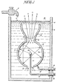
- the housing 10 is a sphere having a gas expulsion opening 8 in its uppermost region, and a gas guide 13 flared out from the opening 8.
- the outer shell 9 of the sphere is the grounded negative side. That is, the negative side of a direct current potential is applied via terminal 16 to the outer shell 9.
- the direct current positive potential is applied thereto via terminal wire 18 extended through a support element 11 entering the housing shell 9 through water intake opening 12.
- the negative potential via terminal 18 is connected to the sphere 9 via terminal 16 and wire 17.
- the vessel/housing 5 contains water 4, replenished by faucet 6, at a level above the entire structure.
- the water 4 is drawn into the outer sphere 9 through the lower opening 12.
- the direct current electrical potential is in the nature of a physical force on the water molecule.
- the sub-atomic action causes the water molecule to break up into its atomic structure -- two parts hydrogen and one part oxygen gas will be liberated from the water. Also other gasses, such as nitrogen, that may be entrapped therein will be released.
- the process does not in fact generate hydrogen but simply releases the hydrogen, the process is most efficient.
- the hydrogen released is much greater than the energy expended. Accordingly, the direct current voltage/potential is of extremely low voltage and only of an insignificant current.
- the preferred embodiment utilizes in one manner or another, all of the aforementioned output control factors and is directed primarily to pulsing the direct ; current potential.
- the structure is constructed to be a resonant cavity at some given frequency of the molecular motion.
- the distance from the outer surface of the central element 15 to the inner surface 9a of the outer spherical element 9 will be at some wavelength to the molecular motion of travel.
- the wavelength is matched with a physical force equal in frequency to that wavelength the inner area becomes a resonant cavity and the water molecule will forcefully be driven repetitively.
- the molecules are set into motion and will bombard back and forth from the one surface to the next continuously so long as the initial force is applied.
- the direction that the water molecules may travel from the inner sphere 15 to the surface 9a of the outer sphere 9 is of an infinite number. Considering a single molecule, the water molecule's motion will under normal conditions be impeded by the water. If the distance between the inner and outer sphere is of a wavelength related to the frequency of the pulsating direct current applied to the water, the water molecule will be set in motion and thereafter enhanced in motion in the resonant cavity 3 and exceed the impediment of water.
- a resonant cavity causes the water molecule to travel back and forth continuously and at a velocity that increases geometrically.
- the enhanced physical action on the water molecule in the resonant cavity 3 will directly affect the breaking up of the molecule into its gasseous atomic structure. As this occurs the hydrogen, oxygen, and-other gasses that may be released from the water will be similarly set into motion. The gas atoms will be reflected from the surface 9a and bombard each other in geometric proportion to the energy applied. The water impediment now is relatively insignificant.
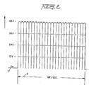
- the direct current input voltage a is pulsed at a repetition rate, as shown by waveform b, (per second) equal to the frequency of the resonant cavity 3.
- the pulsing of the direct current is periodically interrupted as shown in the graph of Figure 2A. That is, the pulse frequency and pulsed direct current c,c l , and c 2 is interrupted in uniform intervals d 1 d 2 , and d 3 .
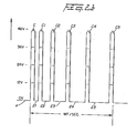
- the pulsed direct current may be aperiodically interrupted. That is, the interruption between pulses c, c 1 ,c 2 , and c 3 ... is for different time periods: e 1 ,e 2 and e 3 .
- an opening 8 is provided in the uppermost portion of the outer sphere 9 of the resonant cavity 3 structure.
- the travel of the gas atoms 7 bombarding back and forth in the resonant cavity 3 will eventually pass through the opening 8.
- the movement of the gas atoms 7 has been enhanced as aforesaid and when they pass through the opening 8 they are at an extremely high velocity. That is, the motion of the gas atoms 7 will pass out of opening 8 as though they are jet propelled.
- Figure 1 The structure of Figure 1 is that of a sphere 9 with another sphere 15 positioned therein.
- the spacing between the outer'surface of the inner sphere 15 to the inner wall 9a of sphere 9 provides a resonant cavity to a given frequency of the physical force of the direct current voltage.
- Other resonant cavities may be utilized in other arrangements.
- the structure of Figure 3 is substantially identical in operation to that of Figure 1.
- the opening 8 and nozzle 2 size is of a controlled diameter.
- the velocity of the gasses being expelled determines the port of the nozzle 2. That is, the port in the nozzle 2 must be sufficiently large to permit an adequate amount Q f. gas to be expelled to maintain a flame. However, the port in the nozzle 2 must not be enlargened to wherein the velocity of the gasses expelled would be so great that combustion cannot be sustained.
- the direction of the high velocity gasses is controlled by guide 13.
- the gasses 7 may be ignited by igniter 25 or utilized directly in another manner.
- the resonant cavities of Figures 1,3, and 7 are related to the spacing between an outside and an inside spherical structure comprising a resonant cavity to the excited elements in a sub-atomic process.
- Other configurations particularly those shown in the aforesaid co-pending patent application, may be constructe or modified to be resonant cavities.
- the resonant cavities will enhance the release of the gasses in the sub-atomic action, irrespective of its configuration. However, which structure is most productive may be related to its utilization in an operable embodiment. .
- the resonant cavity of Figure 4 is an elongated exciter 31.
- the spacing between the elements 33 and 36 provide the resonant cavity.
- the gasses 35 in this embodiment will be jettisoned broadside along the slot 32.
- FIG. 5 there is illustrated the coaxial exciter arrangement of the preferred embodiment of the aforementioned co-pending patent application.
- the spacing 34 between the inner plate 39 and the inner wall of the outer element 37 is adjusted to be resonant at a given frequency.
- the input direct current is pulsed accordingly.
- the gasses are propelled along-the longitudinal axis of the elements 37 and 39 and expelled from the end 38 of the exciter.
- the exciter 40 of Figure 6 is an improvement over the corrugated surface exciter disclosed in my co-pendingvpatent application., Serial Number: 06/367/052.
- the increased surface area provided by the corrugations and creating the resonant cavity thus enhances the sub-atomic action.
- the corrugations provide an enhancement of the sub-atomic action, over that aforesaid, on the water entering at 44.
- the spacing 46 between the plate 41 and 42 is such to be resonant at a particular frequency, as aforementioned.
- the corrugations of the convex 47 and concave 49 surfaces causes the atoms to move in forward and backward / back-and-forth path.
- the increased movement increases the sub-atomic action and the velocity of the flow of gasses 45 ommitted from the end of 43 of the exciter 40.
- the structure of Figure 1 is in an array of resonant cavities 50 a xxx n.
- the housing 51 having a water 52 therein includes the array of exciters, having a positive potential applied to its central element 53 a xxx n, via terminal 64 and a negative potential to the outer element 55 a xxx n.
- the direct current potential is pulsed in a repetitive frequency, as noted above, to match the frequency of the resonant cavity.
- the gasses 54 a xxx n being released from each of the exciters 50 a xxx n is directed by the guide walls 56 to the upper chamber 58 wherein the high velocity gasses 54 are accumulated. As the gasses 54 are accumulated the pressure in the upper chamber 58 increases proportionally.
- the port 2 is controlled.in size of opening relative to the velocity of the gasses. If the port 2 is oversize the velocity of the gasses will be so great that a flame could not be sustained and backfire may occur. Hence the port size is limited.
- the ports 57 a xxx n maybe greater in size than the individual port 2 of Figure 3.
- the individual outputs are not utilized to support a flame hence the significance of limiting the port size and the danger of flashback is not critical
- the outputs from each of the exciters are accumulated as gasses 54.in a master chamber 58.
- FIG 8 there is illustrated an array of the gas exciters illustrated in Figure 3.
- the operation of the individual gas exciters is identical to that of Figure 3 except that in the array the several gas flames from the individual exciters are accumulated in chamber 75.
- plate is used to denote an element as described. It is specifically understood that the term plate is not to be limited to a flat or planar construction, but may be a structure of any configuration.
Landscapes
- Chemical & Material Sciences (AREA)
- Organic Chemistry (AREA)
- Health & Medical Sciences (AREA)
- General Health & Medical Sciences (AREA)
- Engineering & Computer Science (AREA)
- Combustion & Propulsion (AREA)
- Inorganic Chemistry (AREA)
- Electrolytic Production Of Non-Metals, Compounds, Apparatuses Therefor (AREA)
- Oxygen, Ozone, And Oxides In General (AREA)
- Hydrogen, Water And Hydrids (AREA)
Applications Claiming Priority (2)
| Application Number | Priority Date | Filing Date | Title |
|---|---|---|---|
| US42259482A | 1982-09-24 | 1982-09-24 | |
| US422594 | 1982-09-24 |
Publications (2)
| Publication Number | Publication Date |
|---|---|
| EP0103656A2 true EP0103656A2 (de) | 1984-03-28 |
| EP0103656A3 EP0103656A3 (de) | 1984-08-22 |
Family
ID=23675556
Family Applications (1)
| Application Number | Title | Priority Date | Filing Date |
|---|---|---|---|
| EP82111598A Ceased EP0103656A3 (de) | 1982-09-24 | 1982-12-14 | Resonanzkammer für einen Wasserstoffgenerator |
Country Status (2)
| Country | Link |
|---|---|
| EP (1) | EP0103656A3 (de) |
| JP (1) | JPS5959889A (de) |
Cited By (5)
| Publication number | Priority date | Publication date | Assignee | Title |
|---|---|---|---|---|
| WO2004041715A1 (en) * | 2002-11-08 | 2004-05-21 | Hyun-Ik Yang | Apparatus for generating hydrogen gas |
| CN102616738A (zh) * | 2011-01-26 | 2012-08-01 | 李春铜 | 同时生成氢气和氧气的制备方法及制备系统 |
| GB2495787A (en) * | 2011-10-20 | 2013-04-24 | Andrew Gregory Foy | A gas generating cell that uses resonant frequency excitation to separate gases |
| CN109704284A (zh) * | 2019-02-01 | 2019-05-03 | 工业和信息化部威海电子信息技术综合研究中心 | 具有气体波动的分子筛吸附塔制氧装置 |
| CN115474140A (zh) * | 2021-06-11 | 2022-12-13 | 海信视像科技股份有限公司 | 冰箱 |
Families Citing this family (2)
| Publication number | Priority date | Publication date | Assignee | Title |
|---|---|---|---|---|
| RU2506349C2 (ru) * | 2013-01-21 | 2014-02-10 | Геннадий Леонидович Багич | Способ определения максимальной производительности разложения воды и устройство для его осуществления (водородная ячейка) |
| CN106629595B (zh) * | 2016-12-05 | 2019-01-29 | 钟杰豪 | 高压谐频水解制备氢氧的设备 |
Family Cites Families (3)
| Publication number | Priority date | Publication date | Assignee | Title |
|---|---|---|---|---|
| GB1552311A (en) * | 1977-03-10 | 1979-09-12 | Inoue Japax Res | Electrolytic gernaration of hydrogen and oxygen |
| JPS54111502A (en) * | 1978-02-20 | 1979-08-31 | Inoue Japax Res Inc | Gas evolution by electrolysis of water |
| DE2852712C2 (de) * | 1978-12-06 | 1982-11-04 | Hermann 2863 Ritterhude Wolf | Verfahren zur Gewinnung von molekularem Wasserstoff und molekularem Sauerstoff aus Wasser |
-
1982
- 1982-12-14 EP EP82111598A patent/EP0103656A3/de not_active Ceased
-
1983
- 1983-02-15 JP JP58023663A patent/JPS5959889A/ja active Granted
Cited By (6)
| Publication number | Priority date | Publication date | Assignee | Title |
|---|---|---|---|---|
| WO2004041715A1 (en) * | 2002-11-08 | 2004-05-21 | Hyun-Ik Yang | Apparatus for generating hydrogen gas |
| CN102616738A (zh) * | 2011-01-26 | 2012-08-01 | 李春铜 | 同时生成氢气和氧气的制备方法及制备系统 |
| GB2495787A (en) * | 2011-10-20 | 2013-04-24 | Andrew Gregory Foy | A gas generating cell that uses resonant frequency excitation to separate gases |
| CN109704284A (zh) * | 2019-02-01 | 2019-05-03 | 工业和信息化部威海电子信息技术综合研究中心 | 具有气体波动的分子筛吸附塔制氧装置 |
| CN109704284B (zh) * | 2019-02-01 | 2023-11-07 | 工业和信息化部威海电子信息技术综合研究中心 | 具有气体波动的分子筛吸附塔制氧装置 |
| CN115474140A (zh) * | 2021-06-11 | 2022-12-13 | 海信视像科技股份有限公司 | 冰箱 |
Also Published As
| Publication number | Publication date |
|---|---|
| EP0103656A3 (de) | 1984-08-22 |
| JPS5959889A (ja) | 1984-04-05 |
| JPH0345001B2 (de) | 1991-07-09 |
Similar Documents
| Publication | Publication Date | Title |
|---|---|---|
| US7926257B1 (en) | Advanced pulsed plasma thruster with high electromagnetic thrust | |
| US8122701B2 (en) | Electrostatic colloid thruster | |
| US3232046A (en) | Plasma generator and propulsion exhaust system | |
| CN108291337B (zh) | 促进高速应用的定向能量沉积 | |
| US6145298A (en) | Atmospheric fueled ion engine | |
| US6408614B1 (en) | High-power pressure wave source | |
| US7585372B2 (en) | Method and apparatus for generating gas pulses | |
| EP0103656A2 (de) | Resonanzkammer für einen Wasserstoffgenerator | |
| US3263418A (en) | Detonation reaction engine | |
| JPH04232385A (ja) | 改良された電気的−推力変換効率および大なる電圧作動を有するアークジェットノズル | |
| US20180080438A1 (en) | Efficient Electric Spacecraft Propulsion | |
| RU2188084C2 (ru) | Устройство для возбуждения акустического излучения | |
| US4826581A (en) | Controlled process for the production of thermal energy from gases and apparatus useful therefore | |
| US3380249A (en) | Propulsive device | |
| CA1234773A (en) | Resonant cavity hydrogen generator that operates with a pulsed voltage electrical potential | |
| US5503058A (en) | Vectored plasma arc device | |
| CN111194133B (zh) | 一种利用紫外辐射和电子枪产生中性尘埃粒子流的装置 | |
| JPS59501886A (ja) | スパ−クプラグ | |
| JP2006029337A (ja) | イオン駆動装置および推進力発生方法 | |
| CN119429186B (zh) | 一种微波爆震双模式空间推力器 | |
| JP2626419B2 (ja) | 爆轟圧力による水クラスター分解方法及び装置 | |
| Barreto | Ignition by electric sparks | |
| US20240018950A1 (en) | Fusion Thruster | |
| RU2490498C1 (ru) | Пульсирующий детонационный двигатель | |
| Kidin et al. | Possible acoustic source in turbulent combustion |
Legal Events
| Date | Code | Title | Description |
|---|---|---|---|
| PUAI | Public reference made under article 153(3) epc to a published international application that has entered the european phase |
Free format text: ORIGINAL CODE: 0009012 |
|
| AK | Designated contracting states |
Designated state(s): AT BE CH DE FR GB IT LI LU NL SE |
|
| PUAL | Search report despatched |
Free format text: ORIGINAL CODE: 0009013 |
|
| AK | Designated contracting states |
Designated state(s): AT BE CH DE FR GB IT LI LU NL SE |
|
| 17P | Request for examination filed |
Effective date: 19841109 |
|
| STAA | Information on the status of an ep patent application or granted ep patent |
Free format text: STATUS: THE APPLICATION HAS BEEN REFUSED |
|
| 18R | Application refused |
Effective date: 19911004 |