EP0103586B1 - Sputter initiated resonance ionization spectrometry - Google Patents
Sputter initiated resonance ionization spectrometry Download PDFInfo
- Publication number
- EP0103586B1 EP0103586B1 EP83900764A EP83900764A EP0103586B1 EP 0103586 B1 EP0103586 B1 EP 0103586B1 EP 83900764 A EP83900764 A EP 83900764A EP 83900764 A EP83900764 A EP 83900764A EP 0103586 B1 EP0103586 B1 EP 0103586B1
- Authority
- EP
- European Patent Office
- Prior art keywords
- ions
- sample
- electrode
- cloud
- resonance ionization
- Prior art date
- Legal status (The legal status is an assumption and is not a legal conclusion. Google has not performed a legal analysis and makes no representation as to the accuracy of the status listed.)
- Expired
Links
Images


Classifications
-
- H—ELECTRICITY
- H01—ELECTRIC ELEMENTS
- H01J—ELECTRIC DISCHARGE TUBES OR DISCHARGE LAMPS
- H01J49/00—Particle spectrometers or separator tubes
- H01J49/02—Details
- H01J49/10—Ion sources; Ion guns
- H01J49/16—Ion sources; Ion guns using surface ionisation, e.g. field-, thermionic- or photo-emission
- H01J49/161—Ion sources; Ion guns using surface ionisation, e.g. field-, thermionic- or photo-emission using photoionisation, e.g. by laser
- H01J49/164—Laser desorption/ionisation, e.g. matrix-assisted laser desorption/ionisation [MALDI]
-
- G—PHYSICS
- G01—MEASURING; TESTING
- G01N—INVESTIGATING OR ANALYSING MATERIALS BY DETERMINING THEIR CHEMICAL OR PHYSICAL PROPERTIES
- G01N21/00—Investigating or analysing materials by the use of optical means, i.e. using sub-millimetre waves, infrared, visible or ultraviolet light
- G01N21/62—Systems in which the material investigated is excited whereby it emits light or causes a change in wavelength of the incident light
- G01N21/63—Systems in which the material investigated is excited whereby it emits light or causes a change in wavelength of the incident light optically excited
-
- G—PHYSICS
- G01—MEASURING; TESTING
- G01N—INVESTIGATING OR ANALYSING MATERIALS BY DETERMINING THEIR CHEMICAL OR PHYSICAL PROPERTIES
- G01N23/00—Investigating or analysing materials by the use of wave or particle radiation, e.g. X-rays or neutrons, not covered by groups G01N3/00 – G01N17/00, G01N21/00 or G01N22/00
- G01N23/22—Investigating or analysing materials by the use of wave or particle radiation, e.g. X-rays or neutrons, not covered by groups G01N3/00 – G01N17/00, G01N21/00 or G01N22/00 by measuring secondary emission from the material
- G01N23/225—Investigating or analysing materials by the use of wave or particle radiation, e.g. X-rays or neutrons, not covered by groups G01N3/00 – G01N17/00, G01N21/00 or G01N22/00 by measuring secondary emission from the material using electron or ion
-
- H—ELECTRICITY
- H01—ELECTRIC ELEMENTS
- H01J—ELECTRIC DISCHARGE TUBES OR DISCHARGE LAMPS
- H01J49/00—Particle spectrometers or separator tubes
- H01J49/02—Details
- H01J49/10—Ion sources; Ion guns
- H01J49/14—Ion sources; Ion guns using particle bombardment, e.g. ionisation chambers
- H01J49/142—Ion sources; Ion guns using particle bombardment, e.g. ionisation chambers using a solid target which is not previously vapourised
Description
- This invention relates to a method and apparatus of quantitatively analysing for a component in a sample, according to the generic clause of
claims - There are several methods known in the art for determining the concentration of a specific element in samples with relatively high sensitivity. One such method is known as resonance ionization spectroscopy, usually abbreviated as RIS. This method is described in Journal of Mass Spectrometry and Ion Physics,
Volume 34, No. 1/ 2, June 1980, pages 89 to 97, Amsterdam, NL; (Beekman et al) or in U.S. Patent No. 3,987,302 issued to G. S. Hurst, Marvin G. Payne and E. B. Wagner on October 19, 1976. This RIS method, and improvements thereon, is also described in several publications including an article entitled "Counting the Atoms" in the Journal Physics Today, September 1980. Nearly all atoms of the periodic chart can be analysed using RIS; however, the sample must be in the gaseous phase for this method of analysis. This RIS method has the potential of determining one atom of a selected constituent in a sample. - Another sensitive and selective analytical method is known as secondary ion mass spectrometry, normally abbreviated as SIMS. This method is described, for example, in National Bureau of Standards Special Publication No. 427, distributed by the U.S. Department of Commerce on October, 1975. It is the printed proceedings of a workshop on SIMS and ion microprobe mass analysis, and is edited by K. F. J. Heinrich and D. E. Newbury. In general, the SIMS method involves the bombardment of a sample with relatively energetic ions and then measuring the secondary ions emanating from the sample. In order to achieve any selectivity, these secondary ions are subjected to mass analysis so that the ions of a specific mass corresponding to the desired atom are determined. Such methods provide mass selectivity, but not elemental selectivity e.g., isobars cannot be distinguished.
- Another of the recognized problems of the SIMS method is the relatively small quantity of secondary ions that are produced during the bombardment of the sample. Accordingly, it is relatively difficult to determine extremely small numbers of atoms of the desired specie. In addition, quantitative measurements with SIMS are difficult and may be unreliable due to chemical and physical matrix effects which severely affect the secondary ion yield. Furthermore, since various gaseous environments are frequently used to assist in the production of secondary ions, the SIMS method is not applicable to measuring the atoms that also comprise the added environment.
- From the U.S. Patent 3,955,090 a method and an apparatus for sputtering particles of plural isotope types is known. The particles are sputtered by bombardment with particles having a high energy. With a laser radiation, isotopically selective ionization is carried out of at least one isotope type in the sputtered particle flow. Separate collection of the ionized particle is accomplished through application of a magnetic field in the region of ionization.
- It is the task of the present invention to provide a method and an apparatus for quantitatively analysing a component in a sample, having a high sensitivity and selectivity and which is suitable for a greater number of samples than the prior art methods and which allow a controlled quantitative analysis. This task is solved with a method as claimed in
claim 1, and with an apparatus as claimed inclaim 18. - In accordance with the invention, apparatus and a method of operating the apparatus are provided for the sensitive and selective analysis of a specific component in a sample. The sample is subjected to bombardment of energetic particles, such as ions, thereby producing a cloud. containing neutral particles and secondary ions of constituents within the sample. The secondary ions can be separated from the neutral particles, and the remaining neutral particles are then subjected to photons from a laser system having the appropriate wave lengths for the selective ionization of neutral particles of the desired elemental specie. Alternately, all of the sputtered material may be subjected to ionization by RIS. The ions created from the selected specie can be treated in several ways in order to measure the concentration of the component in the sample. Specific of these treatments include direct measurement, time-of-flight mass analysis, r-f quadrupole mass analysis and magnetic mass analysis. If desired, even the isotopic species of the component can be selected for final analysis by the last three named treatments.
-
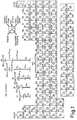
- Figure 1 is a chart showing the elements of the periodic table and various possible resonance ionization spectroscopy schemes that are appropriate for the selective ionization of these elements.
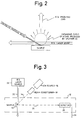
- Figure 2 is a schematic drawing illustrating the principles of the present invention.
- Figure 3 is a schematic drawing illustrating the' principles of the present invention, i.e., sputter initiated resonance ionization spectroscopy, using direct detection of RIS produced ions.
- Figure 4 is a schematic drawing illustrating the principles of the invention using a time-of-flight spectrometer prior to detection of the ions.
- Figure 5 is a schematic drawing illustrating the principles of the present invention using a r-f quadrupole mass spectrometer.
- Figure 6 is a schematic drawing illustrating the principles of sputter initiated resonance ionization spectroscopy using a magnetic sector mass spectrometer.
- Figure 7 is a schematic drawing illustrating the principles of the invention as shown in Figure 6 and the principle of enriching the selected component, or an isotope thereof, in a sample for increased selectivity.
- Figure 8 is a schematic drawing of typical apparatus for carrying out the present invention.
- Figure 9 is an enlarged view of a portion of the apparatus of Figure 8.
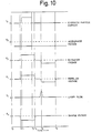
- Figure 10 is a typical plot of the time sequence of the steps involved in the subject invention.
- Figure 11 is a plot illustrating the detection of isotopic species of an element in a sample by varying the magnetic field of a magnetic sector mass spectrometer according to the present invention.
- Figure 12 is a plot illustrating the detection of specific elements in a sample by varying the wavelengths of the laser pulses and simultaneously varying the magnetic field of a magnetic mass spectrometer according to the present invention.
- Referring to Figure 1, shown therein is a chart of the elements of the periodic table. Within each block is indicated the symbol of the element, the energy of the first excited state, the energy of the second excited state (if such is used) and the ionization potential for the element. Furthermore, in the center of each block is designated the particular resonance ionization spectroscopy scheme that may be used to produce ionization of that element.
- Above the chart are shown those specific RIS schemes. In
Scheme 1, used for example with potassium, a photon of a selected wavelength is used to raise an electron in an atom from the ground state up to the first excited state. A second photon of the same wavelength then produces ionization of the atom. Similarly forScheme 3, a photon of a first wavelength excites an atom from its ground state to a first excited state. A photon of a second wavelength further excites the atom to a second excited state, and another photon of either of the wavelengths then completes the ionization process. ThisScheme 3 may be used for producing ions of zirconium, for example. All of the elements of the periodic table, except helium and neon, may be analyzed by using one of the five RIS schemes by employing commercial lasers. - Shown in Figure 2 is the basic principle of the present invention. According to the invention, a sample, which may be either solid or liquid, is bombarded with energetic particles. The energetic particles may be, for example, ions (including electrons) or neutral particles. If the particles have sufficient energy, a cloud of sputtered material will be formed adjacent the surface of the sample. This cloud will contain both charged and neutral particles of substantially all constituents of the sample. The cloud is then subjected to the passage therethrough of one or more laser beams tuned to produce light of wavelengths corresponding to those needed to produce RIS ionization of a particular component of the cloud. The RIS ions thus produced correspond to the component within the sample for which an analysis is desired, and the quantity of these ions can be related to the concentration of that component in the sample.
- Referring now to Figure 3, shown therein are the basic components and principles required for the carrying out of the present invention. A
sample 10 of the material to be investigated is mounted appropriately within an evacuatedcontainer 12. The particular pressure (vacuum) required for the carrying out of the invention will be described in more detail hereinafter. Thesample 10 is bombarded with, in this instance, anion beam 14 as derived from an ion source 16-. Since an ion source may produce ions of other materials than those desired for thebeam 14, a magnetic mass filter as one component ofbeam conditioning apparatus 18 can be utilized to remove the extraneous ions. Theion beam 14, upon striking thesample 10, causes the release of a cloud containing, for example, secondary ions and neutral atoms from the sample. Not shown in this drawing are means for suppressing the secondary ions and leaving the neutral particles for the subsequent analysis steps if this suppression is desired. After the suppression of these secondary ions, alaser beam 20 derived from aRIS laser source 22 is passed through the neutral particles whereupon those materials which correspond to the RIS photon wavelength(s) are ionized. These RIS-produced ions, indicated with theion beam 24 in the drawing, then impinge upon anappropriate ion counter 26 giving rise to an electrical signal onlead 28. Also, not shown herein (or in Figures 4-7) are means for accelerating and/or focusing the RIS-produced ions toward the detector. - Although RIS involves the ionization of atoms of a specific element or molecule through the choice of the laser wavelength, spurious ions having different masses may be produced in some particular applications.
- These may be a small number of ions of other elements which are present in much greater abundance than the element to be detected. State of the art lasers can be used to discriminate isotopes of a given element, but only in certain special cases. On the other hand, it is often generally desired to select ions of a particular mass from the variety actually produced. Thus, incorporated into this invention is the use of a variety of mass spectrometers. One of the simplest ways to obtain information on the mass of an ion is by using a time-of-flight mass spectrometer. This is illustrated in Figure 4. As in Figure 3, an
ion beam 24 that contains predominantly ions of a single element is created by use of RIS on neutral particles generated from asample 10. These ions are then passed through a time-of-flight speetrometer (TOF) 30 prior to impingement upon thedetector 26. A determination of the time between generation of the ions and their arrival at the detector identifies the specific mass(es) of the ion(s) giving rise to the signal(s) onlead 28 thus reducing effects due to spurious ionization in the RIS process. Further, the use of RIS to select the Z (atomic number) of an atom, and a mass spectrometer to select the A (atomic mass) of an atom, gives both Z and A selection on the same atom. For example, isobars in atoms with the same A, but a different Z can be separated in this manner. - Ions produces via the RIS of sputtered atoms may have a relatively wide energy range. Thus, for any type of mass analysis, an
energy filter 32 may be inserted into theion beam 24 prior to the mass analyzer, in this case, theTOF 30. Such an energy filter may also be utilized with the possible variations shown in Figures 5, 6 and 7. - Another method of obtaining information as to the mass of the ion is through use of an r.f. quadrupole
mass spectrometer 34 as shown in Figure 5. Use of a quadrupole provides certain advantages over a TOF analyzer when it is desired to keep the ion energy low, and when better mass selection is needed. - Shown in Figure 6 is another means of mass analysis using a magnetic
sector mass spectrometer 36 interposed in the ion beam ahead of thedetector 26. A magnetic analyzer has the advantages of a very high efficiency (high throughput) and an abundance sensitivity that can be as high as 106 or 107. Thus, additional mass discrimination is achieved. - A further modification of the means of mass analysis shown in Figure 6 is illustrated in Figure 7. Shown therein is a principle of achieving substantially increased abundance sensitivity. lons, after passing through the
sector magnet 36, are imbedded into atarget 38. To achieve incorporation of the ions into the target, an additional acceleration of the ions must be achieved. This can be accomplished by acceleration grids 40 supplied with appropriate voltage(s) from avoltage source 42 throughlead 44. During implantation thedetector 26 measures electrons emitted from the target. - After a substantial fraction of the component of interest in the sample is removed, ionized, and incorporated into the target, this target may be recycled to the sample position. The specie of interest may then be reionized, and the ions again passed through the magnetic mass spectrometer. If the abundance ratio of the mass spectrometer is 106, two passes will give a discrimination of neighboring masses (e.g. isotopes) of 1012; and after n cycles through the spectrometer, a selectivity between adjacent masses is about 106°.
- While the foregoing illustrates the basic principles of the invention, exemplary apparatus for carrying out the invention is illustrated in Figure 8. This is a top cross-sectional view of an
analysis vessel 46 which can be provided, for example, with a plurality of flanged ports 48-58 for purposes hereinafter described. Attached toports flanges beam penetratable window laser beam 68 from a source 70 may be passed through thevessel 46. The source 70 can include means for pulsing the laser beam if desired. Mounted uponport 52 is aflange 72 or other suitable support for a grounded collimating tube 74 leading into thevessel 46. Also attached atport 52 is aflange 76 or other suitable connection for atransport tube 78 leading from a chargedparticle source 80. Thissource 80 gives rise to a chargedparticle beam 82 passing through thetransport tube 78 and collimator 74. Included in thetransport tube 78 and/or thesource 80 can be means (not shown) for the focusing and/or pulsing of the chargedparticle beam 82. - A
sample 84 is positionable proximate the path of thelaser beam 68 with any suitable mechanism. In this view, thesample 84 is at the end ofsample support 86 which, in turn, is mounted from arod 88 using anappropriate fastener 90, for example. Therod 88 passes through aninsulator 92 inflange 94 attached toport 48, and theterminal end 96 of therod 88 is available for the application of a potential E4, if desired. - As shown also in Figure 9, when the
sample 84 is in position for analysis, it is within the base of aFaraday cage 98 having opposedapertures laser beam 68 therethrough. Thecage 98 can be supported from aninsulator 104. This can be supported, in turn, on the end of a group of electrodes 106-114 each separated from each other with appropriate insulators.Electrode 106 can be provided with agrid 116 in theaperture 118 thereof to properly contain the electrical field produced by this electrode. Similar grids can be positioned inelectrodes appropriate flange 126 attached toport 56. In the embodiment shown,electrodes electrode 110. - The
electrode 114 is attached to an inner end of a field-free drift tube 128. Thistube 128 is within a groundedsupport sleeve 130 attached to port 56 with aflange 132 or other suitable means. The outer end of thedrift tube 128 passes through aconduit 134 which may be mounted fromflange 136, for example. The drift tube leads to appropriate ion handling and/oridentification apparatus 138 such as a mass analyzer and/or a detector. - In a normal operation of the apparatus illustrated in Figure 8, a beam of energetic particles, such as electrons, positive ions, etc., is produced at the
source 80 and caused to pass through the collimator 74 to strike thesample 84. This beam produces, adjacent the surface of the sample, a cloud of sputtered material which includes both ions and neutral particles. As discussed above, the passage of an appropriate laser beam (or beams) 68 through this cloud produces selected ions corresponding to the element(s) for which the wavelength(s) of the laser beams are chosen for RIS. The RIS ions are withdrawn into thedrift tube 128 using appropriate potentials on the electrodes 106-114. If the ions produced during sputtering are not to be analyzed, a repelling electrical field can be produced betweenelectrode 106 and the sample 84 (and cage 98) wherein theelectrode 106 is at a more positive potential than the sample until the passage of the laser beam through the cloud. - The apparatus of Figure 8 is primarily intended for pulsed operation, and the various steps of the method are accomplished in a time sequence. For example, a typical time graph of the method is illustrated in Figure 10. During some initial time period, such as from to to t2, there is no energetic particle current striking the
target 84. Then, from time t2 to time t3, theenergetic particle beam 82 is permitted to strike the sample to sputter material therefrom. During approximately the same time interval, or a slightly longer time interval, e.g. t, to t4, positive potentials E, and E2 may be applied toelectrodes sample 84 andcage 98. These potentials, when present onelectrode 106 andsample 84, cause any ions produced during sputtering to be repelled toward the sample and cage. - Shortly after the completion of the charged particle pulse, the laser pulse is produced as at time t5. At or near this time, the potentials E, and E2 are reversed so as to extract RIS ions produced by the
laser beam 68. These potentials are continued, for example, until time ts, to ensure that the RIS ions are drawn into thedrift tube 128. The electrode 110 (andelectrodes 112, 114) may be maintained constantly at potential E3 for assisting in the RIS ion extraction. - Alternatively, the electrode configuration can be altered to permit the passage of the laser beam between the
repeller electrode 106 and theextractor electrode 108. This would necessitate the repositioning and/or shaping of the repeller electrode near the sample. Also, the timing sequence may then require alteration as will be recognized by those versed in the art. 4 - lon detectors, typically electron multiplier detectors, give rise to many spurious signals. Thus, it is necessary to discriminate between these signals and one arising from the ion of interest. One method of accomplishing this is to use a detector gating pulse slightly delayed with respect to the laser pulse. During this interval of the gating pulse, a desired output signal occurs with minimal interference.
- The signal can be made to represent either ions of an element or the isotopes of that element. Referring to Figure 11, for example, shown therein is an illustration of isotope identification of a particular element. As indicated for a specific atomic number, and a constant wavelength(s) laser, a plot of the counts per laser pulse as a function of mass identifies the atomic masses (i.e. isotopes) for that element, e.g., A, A+1, A+2.
- Alternately, for constant A, the wavelength(s) within the laser beam may be changed to discriminate isobars. In this case, the counts per laser pulse for various wavelengths identifies specific elements even in the event of isobars, e.g., (Z1, A1) and (Z2, A1). This is illustrated in Figure 12 which is a bar diagram for various combinations of Z and A. The diagram also shows the more typical case where the wavelength (to specify Z) and the magnetic field (to specify A) are programmed together to compare the abundance of one species (Z3, A3) with that of another (Z4, A4).
- The following example, describing the analysis for specific constituents of a sample, is given to further illustrate the present invention.
- The impurity level of aluminum in silicon is one analysis that is accomplished using the present invention. A small chip of silicon, approximately 0.5x6x6 mm is mounted on the
support 86 such that it is about 1.5 cm away from theextraction electrode 106, and thevessel 46 is evacuated to a pressure of about 5×1.333×10-6 Pa (5×10⁻⁸ Torr). The sample is then baked to a temperature of about 250°C to outgas the sample of residual gas atoms and molecules absorbed from the previous atmospheric environment. Thereafter, the vacuum is increased to about 1.333×10⁻⁷ Pa (10-9 Torr). - A positive Ar ion beam is adjusted to produce a current of about 1 mA with an accelerating potential of about 20 kV. The ion beam is pulsed at a frequency of 10 Hz and at a rate such that a pulse of ions of 2 psec duration strike the target. During the pulse approximate 1.3×10¹⁰ argon ions are focused onto the sample in a 1-2 mm diameter spot. The sputtering yields of aluminum and silicon are both about two neutral atoms per incident ion thus approximately 2.5×10¹⁰ neutral atoms of silicon and a few atoms of aluminum are sputtered from the surface of the sample. The atoms are emitted in various directions in a manner as represented by a cosine distribution. The atoms are also emitted with an average energy of approximate 1.602×10⁻¹⁸ J (10 eV). The sputtered ions (silicon and aluminum) are attracted back to the target with a bias potential of approximately -300 volts between the target and
electrode 106. Neutral atoms of sputtered silicon and aluminum are then intersected by a 1 mm diameter laser beam centered just above the sample surface. - The laser light is typically produced by a Quanta-Ray Model DCR-1A Nd:YAG and Model PDL-1 Dye Laser. The wavelength of the light produced by the laser is tuned to 309,3 nm (3093 A) to excite a neutral atom of aluminum from the ground state to the excited state. Excited aluminum atoms are photoionized by the absorption of a second photon of
wavelength 309,3 nm (3093 A) (Scheme 1, Figure 1). Typically, a Quanta-Ray Model DCR-1A Nd:YAG laser and a Model PDL-1 dye laser using DCM dye supplied by the Exciton Chemical Company, Inc., and a 58° KD*Pfrequency doubling crystal supplied by Quanta-Ray, produces the 309,3 nm (3093Å) lightwith an energy per pulse of 10 millijoules. When this light energy is concentrated into a 1 mm diameter beam, this is equivalent to a photon fluence of 2×10¹⁸ photons/cm2 which is much more than enough to meet the saturation condition. The laser beam is pulsed on about 2.5 psec after the initiation of the ion beam. This time permits movement of both fast and slow neutral aluminum atoms into the laser beam. - For the case of aluminum, the laser will ionize about 1% of the atoms in the selective RIS process. Assuming that all of the ions will be transmitted through the system, and using 6000 laser pulses, one atom of aluminum in 1010 atoms of silicon can be measured to plus or minus 10%. Where additional sensitivity and/or precision is desired, the number of laser pulses can be increased.
- As stated above, the method described with regard to the apparatus of Figure 8 is a pulsed mode method. It is pulsed in two respects; namely, the pulsing of the ion beam striking the sample, and the pulsing of the laser beam. In some analyses, it may be desirable to determine the composition with regard to a particular element at the surface of a sample and thereafter at various depths within the sample. This may be accomplished with the apparatus described herein by first pulsing the ion beam, and through the use of a pulsed laser beam, making an analysis of the composition at the surface., Thereafter, the ion beam may be made to impinge upon the sample for a longer duration and/or with a higher frequency thereby permitting the sputtering away of a portion of the surface. This then permits the analysis for the particular constituent to be repeated at a depth beneath the surface, a technique which is referred to as depth profiling.
Claims (32)
Priority Applications (1)
| Application Number | Priority Date | Filing Date | Title |
|---|---|---|---|
| AT83900764T ATE34086T1 (en) | 1982-01-22 | 1983-01-17 | SPRAYING INDUCED RESONANCE IONIZATION SPECTROMETRY. |
Applications Claiming Priority (2)
| Application Number | Priority Date | Filing Date | Title |
|---|---|---|---|
| US06/341,895 US4442354A (en) | 1982-01-22 | 1982-01-22 | Sputter initiated resonance ionization spectrometry |
| US341895 | 1982-01-22 |
Publications (3)
| Publication Number | Publication Date |
|---|---|
| EP0103586A1 EP0103586A1 (en) | 1984-03-28 |
| EP0103586A4 EP0103586A4 (en) | 1985-09-02 |
| EP0103586B1 true EP0103586B1 (en) | 1988-05-11 |
Family
ID=23339465
Family Applications (1)
| Application Number | Title | Priority Date | Filing Date |
|---|---|---|---|
| EP83900764A Expired EP0103586B1 (en) | 1982-01-22 | 1983-01-17 | Sputter initiated resonance ionization spectrometry |
Country Status (4)
| Country | Link |
|---|---|
| US (1) | US4442354A (en) |
| EP (1) | EP0103586B1 (en) |
| DE (1) | DE3376525D1 (en) |
| WO (1) | WO1983002572A1 (en) |
Families Citing this family (46)
| Publication number | Priority date | Publication date | Assignee | Title |
|---|---|---|---|---|
| US4734579A (en) * | 1983-10-27 | 1988-03-29 | Atom Sciences, Inc. | Ultrasensitive method for measuring isotope abundance ratios |
| US4634864A (en) * | 1983-10-27 | 1987-01-06 | Atom Sciences, Inc. | Ultrasensitive method for measuring isotope abundance ratios |
| WO1985002907A1 (en) * | 1983-12-23 | 1985-07-04 | Sri International | Method and apparatus for surface diagnostics |
| US4633084A (en) * | 1985-01-16 | 1986-12-30 | The United States Of America As Represented By The United States Department Of Energy | High efficiency direct detection of ions from resonance ionization of sputtered atoms |
| US4658135A (en) * | 1985-09-16 | 1987-04-14 | Atom Sciences, Inc. | Method and apparatus for sensitive atom counting with high isotopic selectivity |
| US4664769A (en) * | 1985-10-28 | 1987-05-12 | International Business Machines Corporation | Photoelectric enhanced plasma glow discharge system and method including radiation means |
| US4694167A (en) * | 1985-11-27 | 1987-09-15 | Atom Sciences, Inc. | Double pulsed time-of-flight mass spectrometer |
| US4889987A (en) * | 1986-06-04 | 1989-12-26 | Arch Development Corporation | Photo ion spectrometer |
| US4864130A (en) * | 1986-06-04 | 1989-09-05 | Arch Development Corporation | Photo ion spectrometer |
| IL81375A (en) * | 1987-01-23 | 1990-11-05 | Univ Ramot | Method and apparatus for producing ions by surface ionization of energy-rich molecules and atoms |
| EP0304525A1 (en) * | 1987-08-28 | 1989-03-01 | FISONS plc | Pulsed microfocused ion beams |
| FR2620532B1 (en) * | 1987-09-11 | 1989-12-01 | Cameca | METHOD FOR ANALYZING A SAMPLE BY EROSION USING A PARTICLE BEAM, AND DEVICE FOR CARRYING OUT SAID METHOD |
| GB8928917D0 (en) * | 1989-12-21 | 1990-02-28 | Vg Instr Group | Method and apparatus for surface analysis |
| US5159617A (en) * | 1991-11-13 | 1992-10-27 | Southwest Research Institute | Explosive detection method and apparatus using selective gamma ray resonance absorption |
| US5272338A (en) * | 1992-05-21 | 1993-12-21 | The Pennsylvania Research Corporation | Molecular imaging system |
| US5397895A (en) * | 1992-09-24 | 1995-03-14 | The United States Of America As Represented By The Secretary Of Commerce | Photoionization mass spectroscopy flux monitor |
| US6436635B1 (en) | 1992-11-06 | 2002-08-20 | Boston University | Solid phase sequencing of double-stranded nucleic acids |
| EP1262564A3 (en) | 1993-01-07 | 2004-03-31 | Sequenom, Inc. | Dna sequencing by mass spectrometry |
| US5605798A (en) | 1993-01-07 | 1997-02-25 | Sequenom, Inc. | DNA diagnostic based on mass spectrometry |
| US6194144B1 (en) | 1993-01-07 | 2001-02-27 | Sequenom, Inc. | DNA sequencing by mass spectrometry |
| JPH08190886A (en) * | 1995-01-10 | 1996-07-23 | Mitsubishi Electric Corp | Ion implanting device, ion implanting method, and semiconductor device |
| US6428955B1 (en) | 1995-03-17 | 2002-08-06 | Sequenom, Inc. | DNA diagnostics based on mass spectrometry |
| US7803529B1 (en) | 1995-04-11 | 2010-09-28 | Sequenom, Inc. | Solid phase sequencing of biopolymers |
| US20060063193A1 (en) * | 1995-04-11 | 2006-03-23 | Dong-Jing Fu | Solid phase sequencing of double-stranded nucleic acids |
| US6146854A (en) * | 1995-08-31 | 2000-11-14 | Sequenom, Inc. | Filtration processes, kits and devices for isolating plasmids |
| US5641959A (en) * | 1995-12-21 | 1997-06-24 | Bruker-Franzen Analytik Gmbh | Method for improved mass resolution with a TOF-LD source |
| US5777324A (en) | 1996-09-19 | 1998-07-07 | Sequenom, Inc. | Method and apparatus for maldi analysis |
| ATE259056T1 (en) | 1996-11-06 | 2004-02-15 | Sequenom Inc | METHOD FOR MASS SPECTROMETRY |
| CA2270132A1 (en) * | 1996-11-06 | 1998-05-14 | Sequenom, Inc. | Dna diagnostics based on mass spectrometry |
| DE19649201A1 (en) * | 1996-11-27 | 1998-05-28 | Max Planck Gesellschaft | Electron beam analysis |
| US6207370B1 (en) | 1997-09-02 | 2001-03-27 | Sequenom, Inc. | Diagnostics based on mass spectrometric detection of translated target polypeptides |
| US6268131B1 (en) | 1997-12-15 | 2001-07-31 | Sequenom, Inc. | Mass spectrometric methods for sequencing nucleic acids |
| US6723564B2 (en) | 1998-05-07 | 2004-04-20 | Sequenom, Inc. | IR MALDI mass spectrometry of nucleic acids using liquid matrices |
| US20020142483A1 (en) | 2000-10-30 | 2002-10-03 | Sequenom, Inc. | Method and apparatus for delivery of submicroliter volumes onto a substrate |
| JP4754831B2 (en) * | 2002-10-29 | 2011-08-24 | ターゲット・ディスカバリー・インコーポレイテッド | Method for increasing ionization efficiency of mass spectrometry |
| US7501624B1 (en) | 2005-04-28 | 2009-03-10 | Brookhaven Technology Group, Inc. | System and method for detecting concealed nuclear materials, radiological materials and chemical explosives |
| EP2126957A4 (en) * | 2007-01-19 | 2012-05-30 | Mds Analytical Tech Bu Mds Inc | Apparatus and method for cooling ions |
| WO2009039122A2 (en) | 2007-09-17 | 2009-03-26 | Sequenom, Inc. | Integrated robotic sample transfer device |
| US7982187B2 (en) * | 2008-10-14 | 2011-07-19 | De Gorordo Alvaro Garcia | Method and apparatus for photon-assisted evaluation of a plasma |
| CN102176045B (en) * | 2011-01-20 | 2013-03-13 | 大连理工大学 | Measurement method for spatial distribution of deuterium or tritium detained on surface of first Tokamak wall |
| GB201111568D0 (en) | 2011-07-06 | 2011-08-24 | Micromass Ltd | Apparatus and method of mass spectrometry |
| JP5983447B2 (en) * | 2013-02-06 | 2016-08-31 | 新日鐵住金株式会社 | Unit molecule identification method for polymer material and unit molecule identification apparatus for polymer material |
| JP6343758B2 (en) * | 2013-08-28 | 2018-06-20 | 株式会社トヤマ | Neutral particle mass spectrometer |
| US20170178882A1 (en) * | 2014-04-02 | 2017-06-22 | The Board Of Trustees Of The Leland Stanford Junior University | Apparatus and method for sub-micrometer elemental image analysis by mass spectrometry |
| GB201617628D0 (en) * | 2016-10-18 | 2016-11-30 | University Of Manchester The | Method of determining presence of Isotopes |
| KR102258963B1 (en) * | 2019-09-23 | 2021-06-01 | 한국기초과학지원연구원 | A mass spectrometry system and a mass spectrometry method |
Family Cites Families (7)
| Publication number | Priority date | Publication date | Assignee | Title |
|---|---|---|---|---|
| IL39023A (en) * | 1972-03-19 | 1977-02-28 | Yeshaya Nebenzahl | Isotope separation |
| DE2255302C3 (en) * | 1972-11-11 | 1980-09-11 | Leybold-Heraeus Gmbh, 5000 Koeln | Equipment for secondary ion mass spectroscopy |
| US3953732A (en) * | 1973-09-28 | 1976-04-27 | The University Of Rochester | Dynamic mass spectrometer |
| US3955090A (en) * | 1973-12-27 | 1976-05-04 | Exxon Nuclear Company, Inc. | Sputtered particle flow source for isotopically selective ionization |
| US3987302A (en) * | 1975-08-27 | 1976-10-19 | The United States Of America As Represented By The United States Energy Research And Development Administration | Resonance ionization for analytical spectroscopy |
| US4070580A (en) * | 1976-02-17 | 1978-01-24 | Stanford Research Institute | Method and apparatus for field ionization for isotope separation |
| DE2844002A1 (en) * | 1978-10-09 | 1980-05-14 | Leybold Heraeus Gmbh & Co Kg | METHOD AND DEVICE FOR ANALYZING FLUIDS |
-
1982
- 1982-01-22 US US06/341,895 patent/US4442354A/en not_active Expired - Lifetime
-
1983
- 1983-01-17 DE DE8383900764T patent/DE3376525D1/en not_active Expired
- 1983-01-17 EP EP83900764A patent/EP0103586B1/en not_active Expired
- 1983-01-17 WO PCT/US1983/000084 patent/WO1983002572A1/en active IP Right Grant
Also Published As
| Publication number | Publication date |
|---|---|
| WO1983002572A1 (en) | 1983-08-04 |
| DE3376525D1 (en) | 1988-06-16 |
| EP0103586A4 (en) | 1985-09-02 |
| US4442354A (en) | 1984-04-10 |
| EP0103586A1 (en) | 1984-03-28 |
Similar Documents
| Publication | Publication Date | Title |
|---|---|---|
| EP0103586B1 (en) | Sputter initiated resonance ionization spectrometry | |
| US4633084A (en) | High efficiency direct detection of ions from resonance ionization of sputtered atoms | |
| US7291845B2 (en) | Method for controlling space charge-driven ion instabilities in electron impact ion sources | |
| US4733073A (en) | Method and apparatus for surface diagnostics | |
| US5144127A (en) | Surface induced dissociation with reflectron time-of-flight mass spectrometry | |
| US5032722A (en) | MS-MS time-of-flight mass spectrometer | |
| Parks et al. | Sputter-initiated resonance ionization spectroscopy | |
| US4058724A (en) | Ion Scattering spectrometer with two analyzers preferably in tandem | |
| Price et al. | The renaissance of time-of-flight mass spectrometry | |
| US4864130A (en) | Photo ion spectrometer | |
| US4889987A (en) | Photo ion spectrometer | |
| US6614019B2 (en) | Mass spectrometry detector | |
| Ames et al. | A high-temperature laser ion source for trace analysis and other applications | |
| GB2317047A (en) | Time-of-flight mass spectrometer | |
| JPS6355846A (en) | Secondary neutral particle mass spectrometer | |
| JPS60114753A (en) | Quantitative analysis method of constituent and device thereof | |
| US5784424A (en) | System for studying a sample of material using a heavy ion induced mass spectrometer source | |
| Heinen et al. | Combination of a field desorption ion source with a quadrupole mass analyzer | |
| US4658135A (en) | Method and apparatus for sensitive atom counting with high isotopic selectivity | |
| US4855596A (en) | Photo ion spectrometer | |
| Gilabert et al. | Ultratrace analysis of krypton isotopes by resonant ionization spectroscopy-time of flight mass spectrometry (RIS-TOF) | |
| US5097125A (en) | Photo ion spectrometer | |
| EP0167561B1 (en) | Method and apparatus for surface diagnostics | |
| King et al. | Glow discharge mass spectrometry | |
| Kimock et al. | Matrix effects on the electronic partitioning of iron atoms desorbed from surfaces by energetic ion bombardment |
Legal Events
| Date | Code | Title | Description |
|---|---|---|---|
| PUAI | Public reference made under article 153(3) epc to a published international application that has entered the european phase |
Free format text: ORIGINAL CODE: 0009012 |
|
| 17P | Request for examination filed |
Effective date: 19831124 |
|
| AK | Designated contracting states |
Designated state(s): AT BE CH DE FR GB LI LU NL SE |
|
| EL | Fr: translation of claims filed | ||
| TCAT | At: translation of patent claims filed | ||
| DET | De: translation of patent claims | ||
| 17Q | First examination report despatched |
Effective date: 19860526 |
|
| GRAA | (expected) grant |
Free format text: ORIGINAL CODE: 0009210 |
|
| AK | Designated contracting states |
Kind code of ref document: B1 Designated state(s): AT BE CH DE FR GB LI LU NL SE |
|
| REF | Corresponds to: |
Ref document number: 34086 Country of ref document: AT Date of ref document: 19880515 Kind code of ref document: T |
|
| REF | Corresponds to: |
Ref document number: 3376525 Country of ref document: DE Date of ref document: 19880616 |
|
| ET | Fr: translation filed | ||
| PG25 | Lapsed in a contracting state [announced via postgrant information from national office to epo] |
Ref country code: LU Free format text: LAPSE BECAUSE OF NON-PAYMENT OF DUE FEES Effective date: 19890131 |
|
| PLBE | No opposition filed within time limit |
Free format text: ORIGINAL CODE: 0009261 |
|
| STAA | Information on the status of an ep patent application or granted ep patent |
Free format text: STATUS: NO OPPOSITION FILED WITHIN TIME LIMIT |
|
| 26N | No opposition filed | ||
| PGFP | Annual fee paid to national office [announced via postgrant information from national office to epo] |
Ref country code: SE Payment date: 19900629 Year of fee payment: 8 |
|
| PGFP | Annual fee paid to national office [announced via postgrant information from national office to epo] |
Ref country code: LU Payment date: 19900704 Year of fee payment: 8 |
|
| PGFP | Annual fee paid to national office [announced via postgrant information from national office to epo] |
Ref country code: AT Payment date: 19900713 Year of fee payment: 8 |
|
| PGFP | Annual fee paid to national office [announced via postgrant information from national office to epo] |
Ref country code: CH Payment date: 19900717 Year of fee payment: 8 |
|
| PG25 | Lapsed in a contracting state [announced via postgrant information from national office to epo] |
Ref country code: AT Effective date: 19910117 |
|
| PG25 | Lapsed in a contracting state [announced via postgrant information from national office to epo] |
Ref country code: SE Effective date: 19910118 |
|
| PG25 | Lapsed in a contracting state [announced via postgrant information from national office to epo] |
Ref country code: LI Effective date: 19910131 Ref country code: CH Effective date: 19910131 |
|
| REG | Reference to a national code |
Ref country code: CH Ref legal event code: PL |
|
| PGFP | Annual fee paid to national office [announced via postgrant information from national office to epo] |
Ref country code: BE Payment date: 19930118 Year of fee payment: 11 |
|
| PGFP | Annual fee paid to national office [announced via postgrant information from national office to epo] |
Ref country code: NL Payment date: 19930131 Year of fee payment: 11 |
|
| PG25 | Lapsed in a contracting state [announced via postgrant information from national office to epo] |
Ref country code: BE Effective date: 19940131 |
|
| BERE | Be: lapsed |
Owner name: SCHMITT HAROLD W. Effective date: 19940131 Owner name: PARKS JAMES E. Effective date: 19940131 Owner name: HURST SAMUEL G. Effective date: 19940131 |
|
| PG25 | Lapsed in a contracting state [announced via postgrant information from national office to epo] |
Ref country code: NL Effective date: 19940801 |
|
| NLV4 | Nl: lapsed or anulled due to non-payment of the annual fee | ||
| EUG | Se: european patent has lapsed |
Ref document number: 83900764.8 Effective date: 19910910 |
|
| PGFP | Annual fee paid to national office [announced via postgrant information from national office to epo] |
Ref country code: GB Payment date: 19990317 Year of fee payment: 17 |
|
| PGFP | Annual fee paid to national office [announced via postgrant information from national office to epo] |
Ref country code: FR Payment date: 19990318 Year of fee payment: 17 |
|
| PGFP | Annual fee paid to national office [announced via postgrant information from national office to epo] |
Ref country code: DE Payment date: 19990330 Year of fee payment: 17 |
|
| PG25 | Lapsed in a contracting state [announced via postgrant information from national office to epo] |
Ref country code: GB Free format text: LAPSE BECAUSE OF NON-PAYMENT OF DUE FEES Effective date: 20000117 |
|
| GBPC | Gb: european patent ceased through non-payment of renewal fee |
Effective date: 20000117 |
|
| PG25 | Lapsed in a contracting state [announced via postgrant information from national office to epo] |
Ref country code: FR Free format text: LAPSE BECAUSE OF NON-PAYMENT OF DUE FEES Effective date: 20000929 |
|
| PG25 | Lapsed in a contracting state [announced via postgrant information from national office to epo] |
Ref country code: DE Free format text: LAPSE BECAUSE OF NON-PAYMENT OF DUE FEES Effective date: 20001101 |
|
| REG | Reference to a national code |
Ref country code: FR Ref legal event code: ST |