EP0103498A2 - A sealing ring for an electrical connector - Google Patents
A sealing ring for an electrical connector Download PDFInfo
- Publication number
- EP0103498A2 EP0103498A2 EP83401558A EP83401558A EP0103498A2 EP 0103498 A2 EP0103498 A2 EP 0103498A2 EP 83401558 A EP83401558 A EP 83401558A EP 83401558 A EP83401558 A EP 83401558A EP 0103498 A2 EP0103498 A2 EP 0103498A2
- Authority
- EP
- European Patent Office
- Prior art keywords
- face
- sealing ring
- annular
- groove
- electrical connector
- Prior art date
- Legal status (The legal status is an assumption and is not a legal conclusion. Google has not performed a legal analysis and makes no representation as to the accuracy of the status listed.)
- Withdrawn
Links
Images
Classifications
-
- H—ELECTRICITY
- H01—ELECTRIC ELEMENTS
- H01R—ELECTRICALLY-CONDUCTIVE CONNECTIONS; STRUCTURAL ASSOCIATIONS OF A PLURALITY OF MUTUALLY-INSULATED ELECTRICAL CONNECTING ELEMENTS; COUPLING DEVICES; CURRENT COLLECTORS
- H01R13/00—Details of coupling devices of the kinds covered by groups H01R12/70 or H01R24/00 - H01R33/00
- H01R13/46—Bases; Cases
- H01R13/52—Dustproof, splashproof, drip-proof, waterproof, or flameproof cases
- H01R13/5219—Sealing means between coupling parts, e.g. interfacial seal
Definitions
- This invention relates to an electrical connector and more particularly to a moisture seal.
- An electrical connector assembly is generally comprised of two separate housings connected together by a coupling ring mounted on one of the housings.
- bayonet type couplings which include an internal groove that mates with a pin on a housing, a threaded coupling which includes threads that mate with threads on a housing so that when a coupling member is rotated the housings are drawn together mating the contacts within the housing.
- some connectors provide a rubber 0 ring between the connector housings to provide a moisture seal when the coupling ring is rotated and the housings held together.
- This invention provides an improved moisture seal for an electrical connector assembly.
- the invention is characterized by an annular rubber member having generally flat surfaces and an annular groove in one of the surfaces of the member that abuts against a forward surface of one of the housings.
- a second groove extending radially from the annular groove to a circumferential face provides an escape path for air that would normally be trapped in the annular groove when the sealing member is compressed.
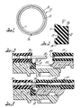
- FIGURES 1 and 2 illustrate an annular sealing member and a cross sectional view of the sealing member which incorporates the principles of this invention.
- FIGURES 3 and 4 illustrate a portion of electrical connector assembly utlizing the invention.
- FIGURE 1 illustrates an annular sealing member 10 comprised of a elastomeric material such as rubber.
- the sealing member 10 includes an inner circumferential face 13, an outer circumferential face 14, a rear face 11 having an annular groove 15 therein, and a second groove 16 extending radially from the first annular groove 15 to the outer circumferential face 14.
- FIGURE 2 is a cross sectional view of the annular member 10 and illustrates how the forward face 12 of annular member 10 has an area less than the area of the rearward face 11 having the annular groove 15 therein.
- FIGURE 3 illustrates a portion of an electrical connector assembly in an unmated position.
- the electrical connector assembly generally includes two separate housings 20, 30 each having inserts 21, 31 mounted therein that have a plurality of contacts 22, 32 mounted therein.
- the annular member 10 is mounted with its rear face 11 in contact with a forward face of the housing 30.
- the inner circumferential face 13 includes an angled surface which fits the angled surface on the connector insert 13 to secure the sealing member 10 in the connector hanging 30.
- the other housing 20 includes an annular projection 25 having a radial width about the same as the diameter of the groove 15.
- FIGURE 4 illustrates how the forward projection 25 on one housing 20 has deformed the annular member 10 so as to virtually eliminate the groove that was in the rear face of the member 10.
- the groove provides space for material displaced by the forward projection 25 of the housing 20 during mating of the contacts 22, 32.
- 30 can be drawn closer together thereby assuring better electrical contact between the mated electrical contacts (32, 22 figure 3).
- the space 15 also allows the projection 25,to penetrate deeper into the sealing member 10 thereby providing a better seal.
- the radially extending groove 16 shown in figure 1 allows the air to escape from the annular groove 15 when the forward projection 25 presses into the annular member 10.
- the sealing member may or may not have the second radially extending groove 16 and still provide substantially all of its advantages. Accordingly, it is intented that the illustrative and descriptive materials herein be used to illustrate the principles of the invention and not to limit the scope thereof.
Landscapes
- Connector Housings Or Holding Contact Members (AREA)
Abstract
Description
- This invention relates to an electrical connector and more particularly to a moisture seal.
- An electrical connector assembly is generally comprised of two separate housings connected together by a coupling ring mounted on one of the housings. In cylindrically shaped connectors there are bayonet type couplings, which include an internal groove that mates with a pin on a housing, a threaded coupling which includes threads that mate with threads on a housing so that when a coupling member is rotated the housings are drawn together mating the contacts within the housing. In many environments water or moisture present in the air present a problem to the electrical connections within a mated electrical connector assembly. Accordingly some connectors provide a rubber 0 ring between the connector housings to provide a moisture seal when the coupling ring is rotated and the housings held together. An example of a multi contact electrical connector having a coupling ring may be found in U.S. Patent 3,221,292 entitled "Electrical Connector" issued November 30, 1965. In some instances, because of the limited space available for the moisture sealing ring, the ring prevents the coupling ring from drawing the housings together as far as would otherwise be possible because there is no place for the deformed material of the O ring to displace itself.
- This invention provides an improved moisture seal for an electrical connector assembly. The invention is characterized by an annular rubber member having generally flat surfaces and an annular groove in one of the surfaces of the member that abuts against a forward surface of one of the housings. A second groove extending radially from the annular groove to a circumferential face provides an escape path for air that would normally be trapped in the annular groove when the sealing member is compressed.
- Accordingly, it is an advantage to provide an improved moisture seal for use in an electrical connector.
- FIGURES 1 and 2 illustrate an annular sealing member and a cross sectional view of the sealing member which incorporates the principles of this invention.
- FIGURES 3 and 4 illustrate a portion of electrical connector assembly utlizing the invention.
- Referring now to drawings FIGURE 1 illustrates an
annular sealing member 10 comprised of a elastomeric material such as rubber. The sealingmember 10 includes an inner circumferential face 13, an outercircumferential face 14, arear face 11 having anannular groove 15 therein, and asecond groove 16 extending radially from the firstannular groove 15 to the outercircumferential face 14. - FIGURE 2 is a cross sectional view of the
annular member 10 and illustrates how theforward face 12 ofannular member 10 has an area less than the area of therearward face 11 having theannular groove 15 therein. - FIGURE 3 illustrates a portion of an electrical connector assembly in an unmated position. The electrical connector assembly generally includes two
separate housings 20, 30 each having inserts 21, 31 mounted therein that have a plurality ofcontacts annular member 10 is mounted with itsrear face 11 in contact with a forward face of thehousing 30. The inner circumferential face 13 includes an angled surface which fits the angled surface on the connector insert 13 to secure the sealingmember 10 in the connector hanging 30. The other housing 20 includes anannular projection 25 having a radial width about the same as the diameter of thegroove 15. When the coupling nut (not shown) mounted on one of thehousings 30 is rotated it draws the twohousings 20, 30 together so that the contacts are mated and the housings compress theannular member 10 as shown in FIGURE 4. - FIGURE 4 illustrates how the
forward projection 25 on one housing 20 has deformed theannular member 10 so as to virtually eliminate the groove that was in the rear face of themember 10. The groove provides space for material displaced by theforward projection 25 of the housing 20 during mating of thecontacts housings 20, 30 can be drawn closer together thereby assuring better electrical contact between the mated electrical contacts (32, 22 figure 3). Thespace 15 also allows theprojection 25,to penetrate deeper into the sealingmember 10 thereby providing a better seal. The radially extendinggroove 16 shown in figure 1 allows the air to escape from theannular groove 15 when theforward projection 25 presses into theannular member 10. - While a preferred embodiment of the invention has been disclosed, it will be apparent to those skilled in the art that changes may be made in the invention as set forth in the appended claims and, in some instances, certain features of the invention may be used to advantage without corresponding use of the other features. For instance, the sealing member may or may not have the second radially extending
groove 16 and still provide substantially all of its advantages. Accordingly, it is intented that the illustrative and descriptive materials herein be used to illustrate the principles of the invention and not to limit the scope thereof.
Claims (6)
Applications Claiming Priority (2)
| Application Number | Priority Date | Filing Date | Title |
|---|---|---|---|
| US402528 | 1982-07-28 | ||
| US06/402,528 US4456320A (en) | 1982-07-28 | 1982-07-28 | Sealing ring for an electrical connector |
Publications (2)
| Publication Number | Publication Date |
|---|---|
| EP0103498A2 true EP0103498A2 (en) | 1984-03-21 |
| EP0103498A3 EP0103498A3 (en) | 1986-09-10 |
Family
ID=23592283
Family Applications (1)
| Application Number | Title | Priority Date | Filing Date |
|---|---|---|---|
| EP83401558A Withdrawn EP0103498A3 (en) | 1982-07-28 | 1983-07-28 | A sealing ring for an electrical connector |
Country Status (4)
| Country | Link |
|---|---|
| US (1) | US4456320A (en) |
| EP (1) | EP0103498A3 (en) |
| JP (1) | JPS5949171A (en) |
| CA (1) | CA1197907A (en) |
Cited By (3)
| Publication number | Priority date | Publication date | Assignee | Title |
|---|---|---|---|---|
| EP0335721A3 (en) * | 1988-03-31 | 1991-05-02 | Molex Incorporated | Waterproof electric connector |
| EP0694995A1 (en) * | 1994-07-29 | 1996-01-31 | Connecteurs Cinch | Seal for water proof connector |
| FR2781313A1 (en) * | 1998-07-17 | 2000-01-21 | Peugeot | Air evacuation arrangement for electrical connector assembly uses sealing strip with flexible upper sides to allow trapped air to escape from inside the connector during insertion coupling movement |
Families Citing this family (8)
| Publication number | Priority date | Publication date | Assignee | Title |
|---|---|---|---|---|
| US4683944A (en) * | 1985-05-06 | 1987-08-04 | Innotech Energy Corporation | Drill pipes and casings utilizing multi-conduit tubulars |
| JPH0531143U (en) * | 1991-09-30 | 1993-04-23 | 株式会社カンセイ | Waterproof connector |
| US5735704A (en) * | 1995-05-17 | 1998-04-07 | Hubbell Incorporated | Shroud seal for shrouded electrical connector |
| US5951595A (en) * | 1996-05-13 | 1999-09-14 | Pacesetteer, Inc. | Setscrewless connector assembly for implantable medical devices |
| US6022237A (en) * | 1997-02-26 | 2000-02-08 | John O. Esh | Water-resistant electrical connector |
| US6102666A (en) * | 1998-12-28 | 2000-08-15 | U.S. Natural Resources, Inc. | Sealed electrical connector assembly |
| US9397441B2 (en) | 2013-03-15 | 2016-07-19 | Cinch Connections, Inc. | Connector with anti-decoupling mechanism |
| DE102016212923B4 (en) * | 2016-07-14 | 2025-02-06 | Te Connectivity Germany Gmbh | Vibration-damping plug with a vibration damper and assembly comprising this plug and a mating plug |
Family Cites Families (9)
| Publication number | Priority date | Publication date | Assignee | Title |
|---|---|---|---|---|
| US2450528A (en) * | 1944-12-18 | 1948-10-05 | H H Buggie & Company | Electrical connector |
| US2655638A (en) * | 1951-09-19 | 1953-10-13 | Harry W Allen | Waterproof and pressureproof connector |
| US3221292A (en) * | 1961-10-18 | 1965-11-30 | Bendix Corp | Electrical connector |
| US3214182A (en) * | 1962-02-27 | 1965-10-26 | Henry J Herbruggen | Packing ring |
| IL43271A (en) * | 1972-09-27 | 1976-07-30 | Bunker Ramo | Electrical connector |
| US3915463A (en) * | 1974-02-21 | 1975-10-28 | Utex Ind Inc | Packing |
| US4109990A (en) * | 1977-05-26 | 1978-08-29 | The Bendix Corporation | Electrical connector assembly having anti-decoupling mechanism |
| GB2061027B (en) * | 1979-10-10 | 1983-05-18 | Itt | Electrical connectors |
| DE3210936C2 (en) * | 1982-03-25 | 1984-12-06 | Robert Bosch Gmbh, 7000 Stuttgart | Connector |
-
1982
- 1982-07-28 US US06/402,528 patent/US4456320A/en not_active Ceased
-
1983
- 1983-03-24 CA CA000424398A patent/CA1197907A/en not_active Expired
- 1983-07-27 JP JP58136020A patent/JPS5949171A/en active Pending
- 1983-07-28 EP EP83401558A patent/EP0103498A3/en not_active Withdrawn
Cited By (4)
| Publication number | Priority date | Publication date | Assignee | Title |
|---|---|---|---|---|
| EP0335721A3 (en) * | 1988-03-31 | 1991-05-02 | Molex Incorporated | Waterproof electric connector |
| EP0694995A1 (en) * | 1994-07-29 | 1996-01-31 | Connecteurs Cinch | Seal for water proof connector |
| FR2723266A1 (en) * | 1994-07-29 | 1996-02-02 | Cinch Connecteurs Sa | SEAL FOR WATERPROOF CONNECTOR |
| FR2781313A1 (en) * | 1998-07-17 | 2000-01-21 | Peugeot | Air evacuation arrangement for electrical connector assembly uses sealing strip with flexible upper sides to allow trapped air to escape from inside the connector during insertion coupling movement |
Also Published As
| Publication number | Publication date |
|---|---|
| EP0103498A3 (en) | 1986-09-10 |
| JPS5949171A (en) | 1984-03-21 |
| CA1197907A (en) | 1985-12-10 |
| US4456320A (en) | 1984-06-26 |
Similar Documents
| Publication | Publication Date | Title |
|---|---|---|
| USRE32787E (en) | Sealing ring for an electrical connector | |
| US4632482A (en) | Contact for an electrical connector | |
| US3827007A (en) | Hermaphroditic electrical connector with front releasable and rear removable electrical contacts | |
| US4150866A (en) | Environmentally sealed connector | |
| US4643506A (en) | Wire seal | |
| US4349241A (en) | Electrical connector assembly having enhanced EMI shielding | |
| US4361374A (en) | Electrical connector bayonet coupling pin | |
| EP0103498A2 (en) | A sealing ring for an electrical connector | |
| ATE254772T1 (en) | UNDERWATER CONNECTOR ARRANGEMENT | |
| EP0221952B1 (en) | Wire seal | |
| KR950002113A (en) | Reduced strain cable connector | |
| US4421373A (en) | Electrical connector having means for sealing against moisture | |
| EP0083884A2 (en) | A moisture seal for a separable electrical connection | |
| JPH0580794B2 (en) | ||
| US4386816A (en) | Electrical connector insert assembly | |
| EP0052538A2 (en) | Electrical connector coupling member | |
| US4527851A (en) | Electrical connector assembly having an interfacial seal | |
| US4406507A (en) | Electrical connector insert | |
| CA1207859A (en) | Electrical connector having a moisture seal | |
| US4857007A (en) | Molded environmental seal for electrical connection | |
| US4387945A (en) | Electrical connector insert | |
| US6109945A (en) | Electrical sealed connector | |
| US4220385A (en) | Electrical connector | |
| US4387943A (en) | Electrical connector having front or rear releasable and removable contacts | |
| US4367002A (en) | Coupling ring having lined bayonet slot |
Legal Events
| Date | Code | Title | Description |
|---|---|---|---|
| PUAI | Public reference made under article 153(3) epc to a published international application that has entered the european phase |
Free format text: ORIGINAL CODE: 0009012 |
|
| AK | Designated contracting states |
Designated state(s): DE FR GB IT |
|
| PUAL | Search report despatched |
Free format text: ORIGINAL CODE: 0009013 |
|
| AK | Designated contracting states |
Kind code of ref document: A3 Designated state(s): DE FR GB IT |
|
| STAA | Information on the status of an ep patent application or granted ep patent |
Free format text: STATUS: THE APPLICATION IS DEEMED TO BE WITHDRAWN |
|
| 18D | Application deemed to be withdrawn |
Effective date: 19870201 |
|
| RIN1 | Information on inventor provided before grant (corrected) |
Inventor name: FREAR, DAVID LEIGH Inventor name: GALLUSSER, DAVID OTIS Inventor name: PUNAKO, STEPHEN Inventor name: MACAVOY, DAVID WARREN |