EP0103434A2 - An outrigger beam assembly for a vehicle and a method for stabilising a vehicle - Google Patents
An outrigger beam assembly for a vehicle and a method for stabilising a vehicle Download PDFInfo
- Publication number
- EP0103434A2 EP0103434A2 EP83304941A EP83304941A EP0103434A2 EP 0103434 A2 EP0103434 A2 EP 0103434A2 EP 83304941 A EP83304941 A EP 83304941A EP 83304941 A EP83304941 A EP 83304941A EP 0103434 A2 EP0103434 A2 EP 0103434A2
- Authority
- EP
- European Patent Office
- Prior art keywords
- outrigger
- extension
- vehicle
- extension beam
- working position
- Prior art date
- Legal status (The legal status is an assumption and is not a legal conclusion. Google has not performed a legal analysis and makes no representation as to the accuracy of the status listed.)
- Withdrawn
Links
Images
Classifications
-
- B—PERFORMING OPERATIONS; TRANSPORTING
- B66—HOISTING; LIFTING; HAULING
- B66C—CRANES; LOAD-ENGAGING ELEMENTS OR DEVICES FOR CRANES, CAPSTANS, WINCHES, OR TACKLES
- B66C23/00—Cranes comprising essentially a beam, boom, or triangular structure acting as a cantilever and mounted for translatory of swinging movements in vertical or horizontal planes or a combination of such movements, e.g. jib-cranes, derricks, tower cranes
- B66C23/62—Constructional features or details
- B66C23/72—Counterweights or supports for balancing lifting couples
- B66C23/78—Supports, e.g. outriggers, for mobile cranes
- B66C23/80—Supports, e.g. outriggers, for mobile cranes hydraulically actuated
Definitions
- the present invention relates generally to an outrigger beam assembly for a vehicle such as a construction vehicle, and a method for stabilising a vehicle. More particularly, it concerns an extension beam which is connected to an outer end of an outrigger beam, which extension beam is selectively pivotable, around a vertical axis, about the outrigger beam from a working position to a non-working or storage position.
- Retractable and extensible outrigger assemblies are usable, for example, on certain utility vehicles for the maintenance of stability of the vehicle and prevention of tipping while the vehicle is performing a work function.
- Such vehicles notably include truck cranes which have to be sufficiently narrow to safely traverse a highway en route to a worksite but need an enlarged pedestal of stability when working at the work site.
- two outrigger assemblies are provided on the vehicle, one located rearwardly of the crane and another one forwardly of the crane.
- Each outrigger assembly normally has one outrigger beam extendable substantially outwardly from each side of the vehicle.
- a float assembly is located at an outer end of an outermost outrigger beam and has a vertically extendable and retractable plate-like foot for engagement with the ground or other support surface. Vertical extension and retraction of these plate-like feet, commonly known as pads or float pads, is generally accomplished by a jack cylinder.
- a road vehicle derrick having two extension beams pivotally mounted to a main beam, about a horizontal axis, is known to the prior art.
- Secured to each end of the main beam are a pair of hinge members and an associated end of each extension beam is provided with an upper lug and a lower lug with the lugs fitting between the sides of the hinge members.
- Passing through each hinge member and a respective upper lug is a bolt with a removable pin being employed to connect the lower end of each hinge member to a respective lower lug.
- the pins When the extension beams are not in use, the pins may be withdrawn and the extension beams pivoted upwardly about the bolts onto a decking of the vehicle.
- Vertically adjustable supports which help stabilise the construction vehicle are located at outer ends of each of the extension beams.
- a truck-mounted scaffold having an outrigger assembly with a pair of telescoping stabilizer bars is also known to the prior art.
- Each stabilizer bar is provided with a jack post at an outer end thereof with the jack posts being pivotable about a horizontal axis from a stored positon to an erect position for use.
- a hook is provided to retain the jack posts in a folded storage position. The hook is welded to a flange on each jack post with the hook engaging a loop fixed to one end of each of the channel members.
- Such an outrigger structure is disclosed by United States Patent No. 3,825,095 issued to Clark. It would be desirable, however, to have an outrigger beam assembly having an extension beam which is pivotable around a vertical axis, for ease of manual handling as explained above, and which can be secured in a storage position by a bracing member or locking bar.
- An excavator having a plurality of folding support legs which are mounted for rotation, of somewhat more than 90°, about a vertical axis is also known to the prior art.
- Such an excavator is disclosed in United States Patent 3,987,563 issued to Baur. It would be desirable, however, to have a hydraulically extensible outrigger beam to the end of which is pivotally connected an extension beam which may be secured in a storage position by a locking bar.
- an extension beam which is pivotable about a vertical axis around an outrigger beam from a storage position to a working position is preferred because manual pivoting of an extension beam around a horizontal axis is not feasible due to the weight of the extension beam.
- Two examples of outrigger assemblies pivoting around a horizontal axis, but hydraulically powered nevertheless, in lightweight vehicles such as backhoes are disclosed in United States Patent Nos. 4,236,643 and 4,256,433.
- Conventional jack cylinder and pad assemblies for vehicle outrigger beams are disclosed in United States Patent Nos. 3,990,714 and 4,071,147.
- An outrigger beam assembly includes at least one single stage outrigger beam and an extension beam which is pivotally connected to an outer end of the outrigger beam. Securing the extension beam to the outrigger beam are at least two selectively removable pins, each pin passing through cooperating hinge portions on the extension beam and the outrigger beam. When at least one of the pins is removed, the extension beam may be pivoted around a hinge line, which is a vertical axis passing through the remaining pin or vertically aligned pins, to move the extension beam from a working position to a non-working or storage position.
- a locking bar may be used to secure the extension beam in the storage position such that one end of the locking bar is pinned to a hinge portion on the extension beam and the other end of the locking bar is pinned to a hinge portion on the outrigger beam.
- hinge portions which would be pinned together if the extension beam were in a working position are spaced apart.
- a pair of apertures may be provided on the hinge portions such that the apertures become aligned when the extension beam is rotated to the storage position. A pin is inserted through the aligned apertures to secure the extension beam in the storage position.
- an outrigger beam assembly includes a construction vehicle 5 having a frame 6 and a crane superstructure 7.
- the vehicle 5 is provided with a front outrigger beam assembly 12 located forwardly of the crane superstructure 7 and a rear outrigger beam assembly 14 located rearwardly of the crane superstructure.
- the outrigger assemblies 12, 14 are useful for increasing the width of the working platform or pedestal of the crane thus increasing either the lift capacity of the crane at the same boom length or increasing the boom length at the same lift capacity.
- the vehicle 5 is normally supported on a plurality of tires 15 but is equipped with front and rear outrigger assemblies 12, 14, so that the entire vehicle can be braced if desired.
- the rear outrigger beam assembly 14 has two single stage outrigger beams 30, 30' and two extension beams 40, 40'.
- the total outrigger spread is twenty-five feet with the outrigger beams 30, 30' each being approximately six feet long and the extension beams 40, 40' each being approximately two feet long.
- the outrigger beams 30, 30' could be extended manually, but in larger construction vehicles the beams are preferably hydraulically extensible because they weigh too much to be easily manipulated manually.
- the extension beams 40, 40' may weigh as much as 350 lbs. An extension beam of this size cannot be easily manipulated because of its weight. If an extension beam 40 of this size were hinged around a horizontal axis the beam would be very difficult to move manually since it would have to be rotated upwardly. If, however, the beam 40 is hinged around a vertical axis, as in the present invention, then, as long as the hinge was adequately lubricated, the beam could be moved by hand since the beam would only have to be rotated sideways.
- the rear outrigger beam assembly 14 may be located anywhere along a rear portion of the vehicle 5 but is preferably located behind a plurality of rear wheels or tires 15 (shown in dotted outlines).
- the plurality of rear wheels 15 contact a support surface such as the ground and the rear outrigger beam assembly 14 is positioned behind the wheels.
- a pad 72 extends downwardly from the extension beam 40, with the pad being actuated by a hydraulically powered jack cylinder 70. To enable the vehicle 5 to traverse the ground surface, the pad 72 is retracted so that it will not provide an obstruction while the vehicle is travelling.
- a locking bar 80 Securing the extension beam 40 in a storage position with regard to the vehicle 5 is a locking bar 80.
- the locking bar 80 is secured on a first end to a hinge portion 39 of an upper plate 32 of the outrigger beam 30 and on a second end to a hinge portion 49 of an upper plate 42 of the extension beam 40 (see also Figure 2).
- the locking bar 80 is made of steel or a similar strong, hard material. Connecting the two ends of the locking bar 80 to the outrigger beam 30 and the extension beam 40, respectively, are two pins 60.
- the extension beam 40 In order to bring the extension beam 40 into a working position, the locking bar 80 and the pins 60 securing it are removed. Thereafter, the extension beam is rotated clockwise around a hinge line formed by a first, vertically aligned pair of pins 60 which hingedly connect the left side of the outrigger beam 30 to the left side of the extension beam 40 when the extension beam is in the storage position (the top one of these two pins 60 can be seen in Figure 2). Because two pairs of vertically aligned pins 60 are used, the hinge line may be established on either side of the outrigger beam 30 and the extension beam 40 as desired. The location of the hinge line would depend on whether it is desired to secure the extension beam 40 in a non-working position forwardly or rearwardly of the outrigger beam 30.
- the extension beam 40 Since the outrigger beam 30 is located on a rear portion of the construction vehicle 5, the extension beam 40 will be rotated clockwise until its right side contacts the outrigger beam 30. With regard to the front outrigger beam assembly 12, to bring its extension beams 40 into a storage position, they may be rotated rearwardly or forwardly as the structure of the construction vehicle 5 permits.
- the two pins 60 which are used to secure the locking bar 80, may be used to secure the hinge portions 49 on the right side of the extension beam 40 to the hinge portions 39 on right side of the outrigger beam 30.
- one pin 60 or more than two vertically aligned pins could be used, instead of exactly two vertically aligned pins, if so preferred or so dictated by the circumstances.
- each pin 60 securing the outrigger beam 30 to the extension beam 40 is itself secured against vertical movement by a removable fastener such as a cotter pin 65.
- the several pins 60 and the cotter pin 65 associated with each pin 60 are also preferably made of a suitably strong and wear-resistant material such as steel.
- a hydraulic line or hose 74 conveying hydraulic fluid to the hydraulic cylinder 70 of the pad extension assembly is held in place by a hydraulic hose support plate 50 located in and secured to the extension beam 40 in any conventional fashion such as by welding.
- the extension beam 40 also has a lower plate 43 and a pair of side plates which connect the upper plate to the lower plate (the side plates cannot be seen in Figure 5 because the side plates of the outrigger beam 30 obscure the view).
- the upper and lower plates 42, 43 and the two side plates are preferably welded together but they may be secured in any suitable conventional fashion.
- the several plates are made of steel or another strong, rigid material.
- Four hinge support plates 44, 45, 46, 47 also preferably made from steel or a similar material, are secured in any conventional fashion such as welding to outer surfaces of the two side plates of the extension beam 40.
- the four hinge support plates 44, 45, 46, 47 are so situated that, for example, a pin 60 may pass through a respective pin aperture 41 in a right portion of the upper plate 42 and its respective hinge support plate 44, or a right portion of the lower plate 43, and its respective hinge support plate 45.
- the outrigger beam 30 includes the upper plate 32 and left and right support plates 36, 37 which connect the upper plate to a lower plate 33.
- the four plates 30, 32, 36, 37 are welded together but they may be secured in any suitable conventional fashion.
- the plates of the outrigger beam 30 are made of steel or a similar strong, hard material.
- Reinforcing plates 34, 35 made of a suitable strong material such as steel, are respectively secured, preferably by welding, to an underside of the upper plate 32 and to an upper side of the lower plate 33.
- These reinforcing plates 34, 35 are trapezoidal in shape (see the dotted trapezoidal outline at the outer end of the outrigger beam 30 in Figure 6).
- Such reinforcing plates 34 are useful to strengthen the end portion of the outrigger beam 30 and also to properly space, vertically, the outrigger beam 30 with respect to the extension beam 40.
- the extension beam 40 is secured to the outrigger beam 30 by four selectively removable pins 60, the extension beam can be entirely disconnected from the outrigger beam. Such a disconnection would be useful, for example, if it became necessary to replace the extension beam 40 with one that was longer or shorter. Also, it might be deemed necessary to disconnect the extension beam 40 to replace or repair the hydraulic cylinder 70 or if it was desired to store the extension beam disconnected from the outrigger beam. It might also be deemed necessary to disconnect the extension beams 40 to lighten the vehicle 5 for highway transit. Of course, in most of the above-enumerated instances, it would probably be also necessary to disconnect the hydraulic hose 74.
- the extension beam 40 can be secured by the pins 60 in a working position on the outrigger beam 30 and the outrigger beam can then be extended, preferably hydraulically. Because the extension beam 40 is secured in a working position on the outrigger beam 30, the locking bar 80 is no longer needed and may be stored on a side of the extension beam 40 by, for example, two hooks 82.
- a rod 22 can be hydraulically driven by a cylinder 24 to move the outrigger beam 30 horizontally outwardly from a retracted position to an extended position with respect to the vehicle 5. Extending through a portion of the outrigger beam 30 and the extension beam 40 (the latter not being illustrated in cut-away) is the hydraulic line 74 which provides fluid power for the hydraulic jack cylinder 70 to move the pad 72 into a ground contacting position.
- outrigger beam 30 can be placed in any one of numerous positions from fully retracted to fully extended, as desired. It may be necessary sometimes to only partially extend the outrigger beam 30 as dictated by a particular work situation.
- a cut-out 51 is provided in the upper plate 42 of the extension beam 40 so that the hydraulic line 74 providing hydraulic fluid for powering the hydraulic jack cylinder 70 may be connected to the hydraulic cylinder.
- the left and right sides of the rear outrigger beam assembly 14 are each provided with individual rods 22, 22' and cylinders 24, 24' housed in their own casings 18, 18'.
- a more compact storage arrangement is provided for the extension beam 40 so that the overall width of the construction vehicle 5 is not increased by the utilization of the extension beam.
- another way of securing the extension beam 40 in a non-working position with respect to the outrigger beam 30 modifies some of the hinge portions 39, 49 of the respective beams. Looking at the outrigger beam 30 from the end of the extension beam 40, the left sides of the cooperating hinge portions 39, 49 have been replaced by modified respective hinge portions or ears 139, 149. Each ear 139, 149 is larger in size than the hinge portions 39, 49 and is provided with two pin apertures 41 through which the securing pins 60 may pass.
- respective pins 60 are secured through respective apertures 41 on the hinge portions 39, 49 as in the above-described embodiments. Also, respective pins 60 are secured through the outer cooperating apertures 41 in the ear portions 139, 149. The other or inner apertures 41 in each ear portion 139, 149 remain unused while the extension beam 40 is in the working position.
- the pins 60 connecting the hinge portions 39, 49 are removed. Thereupon, the extension beam 40 can be rotated around the outrigger beam 30 about a hinge line A passing through the remaining pins 60 connecting the respective ear portions 139, 149.
- the pin 60 may be inserted through the apertures 41 to hold the extension beam in the non-working position.
- the ears 139, 149 may be provided on both the top and bottom surfaces of the outrigger beam 30 and the extension beam 40.
- the inner or second apertures 41 may, however, be omitted from each of the ear portions 139, 149 on the bottom surfaces of the outrigger beam and extension beam if desired.
- separate ear portions spaced from the above disclosed hinge portions 39, 49 could be provided on the beams 30, 40, instead of the ears 139, 149 with two apertures, to secure the extension beam in the non-working position.
- An extension beam stop bar 190 may be secured to the casing 18 of the right portion of the rear outrigger assembly 14 to prevent the extension beam 40 from pivoting too far around the outrigger beam 30 and damaging either the extension beam or the casing 18, 18' of the outrigger assembly 14.
- a similar storage arrangement for the extension beam 40 could be provided for the front outrigger assembly 12 if the position of the front outrigger assembly were changed on the vehicle 5 so that the extension beams 40 were able to pivot 1800.
- the vehicle 5 is in a transport mode with both rear extension beams 40, 40' being secured in their storage positions adjacent to sides of the vehicle.
- the four extension beams 40, 40' may be put into their working positions. This is accomplished by removal of each of the locking bars 80 upon removal of the pins 60 connecting the ends of the locking bar to the extension beam 40 and the outrigger beam 30 respectively.
- extension beam 40 of the right outrigger assembly 12 may be pivoted to a working position around a vertical hinge axis passing through the two pins 60 connecting the left side of the extension beam 40 to the left side of the outrigger beam 30 (see Figure 9).
- the left extension beam 40' of the rear outrigger assembly 14 may be similarly pivoted into its working position.
- reconnection of two pins 60 through the cooperating hinge portions 39 of the outrigger beam 30 and hinge portions 49 of the extension beam 40 secures the extension beam in the working position.
- One pin 60 passes through pin apertures 41 in the right portion of the upper plate 42 and the right upper hinge support plate 44 of the extension beam 40 as well as through an aligned, pin aperture 41 through the upper plate 32 and the upper reinforcing plate 34 of the outrigger beam 30.
- Another pin 60 passes through aligned pin apertures 41 in the right lower hinge support plate 45 of the extension beam 40, the lower plate 33 and lower reinforcing plate 35 of the outrigger beam 30 and the right portion of the lower plate 43 of the extension beam.
- Each pin 60 is then secured in place with a respective cotter pin 65. Similar reconnection of another two pins 60 will secure the left extension beam 40' of the rear outrigger assembly 14 in its working position.
- the outrigger beams can be actuated via their respective hydraulic piston and cylinder assemblies to extend the outrigger beams into a working position with regard to the vehicle 5.
- the pads 72 located at a lower end of the pad extension hydraulic jack cylinder 70 can be actuated into a ground contacting position so that the vehicle 5 may be braced as desired.
- the pads 72 could be extended further vertically than to just a ground contacting position. In such an instance, the entire weight of the vehicle can be supported by the pads 72 on outer ends of the outrigger assemblies rather than the wheels 15 of the vehicle 5. Once the vehicle 5 is lifted (see Figure 1), the working platform of the crane may also be levelled by differential vertical extension of the several pads 72.
- the manually pivotable extension beam of the present invention enables the gross weight of the vehicle to be less than would be the case with a conventional vehicle having either a heavier counterweight or a two stage hydraulically actuated outrigger assembly. Such a lesser vehicle weight is advantageous in order to improve the fuel economy of the vehicle when it is moving from place to place and lessens the wear and tear on the vehicle and also on the road surface which is traversed by the vehicle.
Landscapes
- Engineering & Computer Science (AREA)
- Mechanical Engineering (AREA)
- Vehicle Cleaning, Maintenance, Repair, Refitting, And Outriggers (AREA)
- Jib Cranes (AREA)
Abstract
@ An outrigger beam assembly for stabilizing a large construction vehicle (5) includes two pivotally connected portions. Mounted to an outer end of a single stage outrigger beam (30) is an extension beam (40) with selectively removable pins (60) securing the extension beam (40) to the outrigger beam (30). When a vertically aligned pair of pins (60) are removed, the extension beam (40) may be manually pivoted, around a vertical hinge axis passing through the remaining pins (60), from a working position to a non-working or storage position. Either a locking bar (80) or cooperating apertured ear portions on the extension beam (40) and the outrigger beam (30) may be used to secure the extension beam (40) in the storage position.
Description
- The present invention relates generally to an outrigger beam assembly for a vehicle such as a construction vehicle, and a method for stabilising a vehicle. More particularly, it concerns an extension beam which is connected to an outer end of an outrigger beam, which extension beam is selectively pivotable, around a vertical axis, about the outrigger beam from a working position to a non-working or storage position.
- Retractable and extensible outrigger assemblies are usable, for example, on certain utility vehicles for the maintenance of stability of the vehicle and prevention of tipping while the vehicle is performing a work function. Such vehicles notably include truck cranes which have to be sufficiently narrow to safely traverse a highway en route to a worksite but need an enlarged pedestal of stability when working at the work site. Usually, two outrigger assemblies are provided on the vehicle, one located rearwardly of the crane and another one forwardly of the crane. Each outrigger assembly normally has one outrigger beam extendable substantially outwardly from each side of the vehicle. A float assembly is located at an outer end of an outermost outrigger beam and has a vertically extendable and retractable plate-like foot for engagement with the ground or other support surface. Vertical extension and retraction of these plate-like feet, commonly known as pads or float pads, is generally accomplished by a jack cylinder.
- Difficulties have, however, been encountered with conventional construction vehicles having a single stage outrigger beam because the outrigger spread provided by the single stage outrigger beam is not adequate to stabilise the construction vehicle under some circumstances. For example, with a larger outrigger spread, a mobile crane is allowed to have either a greater lift capacity at the same boom length or the same lift capacity at a longer boom length without, in either case, a decrease in stability for the crane. It is evident that the length of a single stage outrigger beam is limited by the width of the vehicle into which the beam is retractable. Naturally, multi-stage hydraulically extensible outrigger beam assemblies could be used, however, such assemblies are much more expensive, and more complex mechanically, than a single stage outrigger beam assembly would be.
- Various arrangements have been disclosed to increase the outrigger spread of a construction vehicle without resorting to multi-stage outrigger structures. When, instead of a multi-stage outrigger beam, an extension beam is secured to the end of a single stage outrigger beam, a longer outrigger spread is afforded without having to resort to a two stage outrigger beam with its accompanying piston and cylinder complications as well as much greater cost and complexity. Such a system would have a lighter weight than a multi-stage outrigger system thereby improving the fuel economy of the vehicle. Alternatively, with the use of a longer outrigger spread, a lighter counterweight could be used thus also decreasing the weight of the vehicle thereby improving its fuel economy and lessening the wear and tear on both the vehicle and the road surface which is traversed by the vehicle.
- A road vehicle derrick having two extension beams pivotally mounted to a main beam, about a horizontal axis, is known to the prior art. Secured to each end of the main beam are a pair of hinge members and an associated end of each extension beam is provided with an upper lug and a lower lug with the lugs fitting between the sides of the hinge members. Passing through each hinge member and a respective upper lug is a bolt with a removable pin being employed to connect the lower end of each hinge member to a respective lower lug. When the extension beams are not in use, the pins may be withdrawn and the extension beams pivoted upwardly about the bolts onto a decking of the vehicle. Vertically adjustable supports which help stabilise the construction vehicle are located at outer ends of each of the extension beams. Such a known outrigger structure is disclosed in United States Patent No. 2,519,910 issued to Kershaw. It would be desirable, however, to provide an outrigger extension which is mounted for pivotal movement around a vertical axis since an extension pivotable around a horizontal axis is unsuitable in a large assembly because it is too heavy to manipulate manually. Also, it would be desirable to provide an extension beam which can be secured in a storage position by a locking bar or bracing member.
- A truck-mounted scaffold having an outrigger assembly with a pair of telescoping stabilizer bars is also known to the prior art. Each stabilizer bar is provided with a jack post at an outer end thereof with the jack posts being pivotable about a horizontal axis from a stored positon to an erect position for use. To retain the jack posts in a folded storage position, a hook is provided. The hook is welded to a flange on each jack post with the hook engaging a loop fixed to one end of each of the channel members. Such an outrigger structure is disclosed by United States Patent No. 3,825,095 issued to Clark. It would be desirable, however, to have an outrigger beam assembly having an extension beam which is pivotable around a vertical axis, for ease of manual handling as explained above, and which can be secured in a storage position by a bracing member or locking bar.
- An excavator having a plurality of folding support legs which are mounted for rotation, of somewhat more than 90°, about a vertical axis is also known to the prior art. Such an excavator is disclosed in United States Patent 3,987,563 issued to Baur. It would be desirable, however, to have a hydraulically extensible outrigger beam to the end of which is pivotally connected an extension beam which may be secured in a storage position by a locking bar.
- To extend the outrigger spread of a larger construction vehicle, an extension beam which is pivotable about a vertical axis around an outrigger beam from a storage position to a working position is preferred because manual pivoting of an extension beam around a horizontal axis is not feasible due to the weight of the extension beam. Two examples of outrigger assemblies pivoting around a horizontal axis, but hydraulically powered nevertheless, in lightweight vehicles such as backhoes are disclosed in United States Patent Nos. 4,236,643 and 4,256,433. Conventional jack cylinder and pad assemblies for vehicle outrigger beams are disclosed in United States Patent Nos. 3,990,714 and 4,071,147.
- An outrigger beam assembly according to the present invention includes at least one single stage outrigger beam and an extension beam which is pivotally connected to an outer end of the outrigger beam. Securing the extension beam to the outrigger beam are at least two selectively removable pins, each pin passing through cooperating hinge portions on the extension beam and the outrigger beam. When at least one of the pins is removed, the extension beam may be pivoted around a hinge line, which is a vertical axis passing through the remaining pin or vertically aligned pins, to move the extension beam from a working position to a non-working or storage position. A locking bar may be used to secure the extension beam in the storage position such that one end of the locking bar is pinned to a hinge portion on the extension beam and the other end of the locking bar is pinned to a hinge portion on the outrigger beam. In this way, hinge portions which would be pinned together if the extension beam were in a working position are spaced apart. Alternatively a pair of apertures may be provided on the hinge portions such that the apertures become aligned when the extension beam is rotated to the storage position. A pin is inserted through the aligned apertures to secure the extension beam in the storage position.
- Some embodiments of the invention are described in detail below, by way of example, with reference to the accompanying drawings wherein like members bear like reference numerals and wherein:-
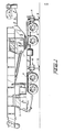
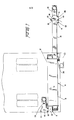
- Figure 1 is a side elevational view of a vehicle provided with outrigger beam assemblies of the present invention secured in a working position;
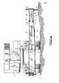
- Figure 2 is a reduced partial plan view of the vehicle of Figure 1 with the rear outrigger beam assembly having two extension beams and both extension beams being secured in a storage position;
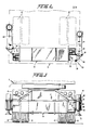
- Figure 3 is an end elevational view of the vehicle of Figure 2;
- Figure 4 is a reduced end elevational view, with portions cut-away for the sake of clarity, similar to Figure 3 with one extension beam connected in a working position to an outrigger beam;
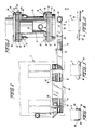
- Figure 5 is an enlarged cross-sectional view taken along line 5-5 of Figure 4;
- Figure 6 is a plan view of Figure 4;
- Figure 7 is a plan view of an alternate embodiment of the outrigger beam assembly according to the present invention;
- Figure 8 is a schematic plan view of the outrigger beam assembly of the present invention with both extension beams in a stored position;
- Figure 9 is a schematic plan view similar to Figure 7 with both extension beams located in a working position; and
- Figure 10 is a schematic plan view similar to Figure 7 with both outrigger beams extended.
- With reference to Figure 1, a preferred embodiment of an outrigger beam assembly according to the present invention includes a
construction vehicle 5 having aframe 6 and acrane superstructure 7. Thevehicle 5 is provided with a frontoutrigger beam assembly 12 located forwardly of thecrane superstructure 7 and a rearoutrigger beam assembly 14 located rearwardly of the crane superstructure. The outrigger assemblies 12, 14 are useful for increasing the width of the working platform or pedestal of the crane thus increasing either the lift capacity of the crane at the same boom length or increasing the boom length at the same lift capacity. Thevehicle 5 is normally supported on a plurality oftires 15 but is equipped with front andrear outrigger assemblies - Because the front and rear assemblies are identical, except for their position on the
vehicle 5, only therear assembly 14 will be discussed. With reference now to Figure 2, the rearoutrigger beam assembly 14 has two singlestage outrigger beams 30, 30' and twoextension beams 40, 40'. In one preferred embodiment, the total outrigger spread is twenty-five feet with theoutrigger beams 30, 30' each being approximately six feet long and theextension beams 40, 40' each being approximately two feet long. Theoutrigger beams 30, 30' could be extended manually, but in larger construction vehicles the beams are preferably hydraulically extensible because they weigh too much to be easily manipulated manually. - In large vehicles, e.g., mobile cranes, the
extension beams 40, 40' may weigh as much as 350 lbs. An extension beam of this size cannot be easily manipulated because of its weight. If anextension beam 40 of this size were hinged around a horizontal axis the beam would be very difficult to move manually since it would have to be rotated upwardly. If, however, thebeam 40 is hinged around a vertical axis, as in the present invention, then, as long as the hinge was adequately lubricated, the beam could be moved by hand since the beam would only have to be rotated sideways. - Since the left and right sides of the
rear outrigger assembly 14 are identical except for their position on the vehicle, only the right side will be described in detail. It is understood that the left side of therear outrigger assembly 14 is identical to the right side. The rearoutrigger beam assembly 14 may be located anywhere along a rear portion of thevehicle 5 but is preferably located behind a plurality of rear wheels or tires 15 (shown in dotted outlines). - With reference now to Figure 3, the plurality of
rear wheels 15 contact a support surface such as the ground and the rearoutrigger beam assembly 14 is positioned behind the wheels. Apad 72 extends downwardly from theextension beam 40, with the pad being actuated by a hydraulically poweredjack cylinder 70. To enable thevehicle 5 to traverse the ground surface, thepad 72 is retracted so that it will not provide an obstruction while the vehicle is travelling. - Securing the
extension beam 40 in a storage position with regard to thevehicle 5 is a lockingbar 80. The lockingbar 80 is secured on a first end to ahinge portion 39 of anupper plate 32 of theoutrigger beam 30 and on a second end to ahinge portion 49 of anupper plate 42 of the extension beam 40 (see also Figure 2). - Preferably, the locking
bar 80 is made of steel or a similar strong, hard material. Connecting the two ends of the lockingbar 80 to theoutrigger beam 30 and theextension beam 40, respectively, are twopins 60. - In order to bring the
extension beam 40 into a working position, the lockingbar 80 and thepins 60 securing it are removed. Thereafter, the extension beam is rotated clockwise around a hinge line formed by a first, vertically aligned pair ofpins 60 which hingedly connect the left side of theoutrigger beam 30 to the left side of theextension beam 40 when the extension beam is in the storage position (the top one of these twopins 60 can be seen in Figure 2). Because two pairs of vertically alignedpins 60 are used, the hinge line may be established on either side of theoutrigger beam 30 and theextension beam 40 as desired. The location of the hinge line would depend on whether it is desired to secure theextension beam 40 in a non-working position forwardly or rearwardly of theoutrigger beam 30. - Since the
outrigger beam 30 is located on a rear portion of theconstruction vehicle 5, theextension beam 40 will be rotated clockwise until its right side contacts theoutrigger beam 30. With regard to the frontoutrigger beam assembly 12, to bring its extension beams 40 into a storage position, they may be rotated rearwardly or forwardly as the structure of theconstruction vehicle 5 permits. The twopins 60, which are used to secure the lockingbar 80, may be used to secure thehinge portions 49 on the right side of theextension beam 40 to thehinge portions 39 on right side of theoutrigger beam 30. Of course, onepin 60 or more than two vertically aligned pins could be used, instead of exactly two vertically aligned pins, if so preferred or so dictated by the circumstances. - With reference now to Figure 5, each
pin 60 securing theoutrigger beam 30 to theextension beam 40 is itself secured against vertical movement by a removable fastener such as acotter pin 65. The several pins 60 and thecotter pin 65 associated with eachpin 60 are also preferably made of a suitably strong and wear-resistant material such as steel. A hydraulic line orhose 74 conveying hydraulic fluid to thehydraulic cylinder 70 of the pad extension assembly is held in place by a hydraulichose support plate 50 located in and secured to theextension beam 40 in any conventional fashion such as by welding. Besides theupper plate 42, theextension beam 40 also has alower plate 43 and a pair of side plates which connect the upper plate to the lower plate (the side plates cannot be seen in Figure 5 because the side plates of theoutrigger beam 30 obscure the view). The upper andlower plates - Preferably, the several plates are made of steel or another strong, rigid material. Four
hinge support plates extension beam 40. The fourhinge support plates pin 60 may pass through arespective pin aperture 41 in a right portion of theupper plate 42 and its respectivehinge support plate 44, or a right portion of thelower plate 43, and its respectivehinge support plate 45. - Included in the
outrigger beam 30 are theupper plate 32 and left andright support plates lower plate 33. Preferably, the fourplates outrigger beam 30 are made of steel or a similar strong, hard material. Reinforcingplates upper plate 32 and to an upper side of thelower plate 33. These reinforcingplates outrigger beam 30 in Figure 6). Such reinforcingplates 34 are useful to strengthen the end portion of theoutrigger beam 30 and also to properly space, vertically, theoutrigger beam 30 with respect to theextension beam 40. - Because the
extension beam 40 is secured to theoutrigger beam 30 by four selectivelyremovable pins 60, the extension beam can be entirely disconnected from the outrigger beam. Such a disconnection would be useful, for example, if it became necessary to replace theextension beam 40 with one that was longer or shorter. Also, it might be deemed necessary to disconnect theextension beam 40 to replace or repair thehydraulic cylinder 70 or if it was desired to store the extension beam disconnected from the outrigger beam. It might also be deemed necessary to disconnect the extension beams 40 to lighten thevehicle 5 for highway transit. Of course, in most of the above-enumerated instances, it would probably be also necessary to disconnect thehydraulic hose 74. - On the other hand, rather than using four selectively
removable pins 60, it would also be feasible to use one or more permanent hinges to connect one side of theextension beam 40 andoutrigger beam 30 and one or moreremovable pins 60 on the other side of the twobeams - With reference now to Figure 4, the
extension beam 40 can be secured by thepins 60 in a working position on theoutrigger beam 30 and the outrigger beam can then be extended, preferably hydraulically. Because theextension beam 40 is secured in a working position on theoutrigger beam 30, the lockingbar 80 is no longer needed and may be stored on a side of theextension beam 40 by, for example, two hooks 82. Arod 22 can be hydraulically driven by acylinder 24 to move theoutrigger beam 30 horizontally outwardly from a retracted position to an extended position with respect to thevehicle 5. Extending through a portion of theoutrigger beam 30 and the extension beam 40 (the latter not being illustrated in cut-away) is thehydraulic line 74 which provides fluid power for thehydraulic jack cylinder 70 to move thepad 72 into a ground contacting position. - It may sometimes be necessary to extend only the front or
rear outrigger assemblies outrigger beam 30 can be placed in any one of numerous positions from fully retracted to fully extended, as desired. It may be necessary sometimes to only partially extend theoutrigger beam 30 as dictated by a particular work situation. - With reference now to Figure 6, a cut-out 51 is provided in the
upper plate 42 of theextension beam 40 so that thehydraulic line 74 providing hydraulic fluid for powering thehydraulic jack cylinder 70 may be connected to the hydraulic cylinder. The left and right sides of the rearoutrigger beam assembly 14 are each provided withindividual rods 22, 22' andcylinders 24, 24' housed in theirown casings 18, 18'. - In an alternate embodiment, a more compact storage arrangement is provided for the
extension beam 40 so that the overall width of theconstruction vehicle 5 is not increased by the utilization of the extension beam. With reference now to Figure 7, another way of securing theextension beam 40 in a non-working position with respect to theoutrigger beam 30 modifies some of thehinge portions outrigger beam 30 from the end of theextension beam 40, the left sides of the cooperatinghinge portions ears ear hinge portions pin apertures 41 through which the securing pins 60 may pass. - When the
extension beam 40 is secured in the working position on theoutrigger beam 30,respective pins 60 are secured throughrespective apertures 41 on thehinge portions respective pins 60 are secured through the outer cooperatingapertures 41 in theear portions inner apertures 41 in eachear portion extension beam 40 is in the working position. - In order to move the
extension beam 40 to a non-working position, thepins 60 connecting thehinge portions extension beam 40 can be rotated around theoutrigger beam 30 about a hinge line A passing through the remainingpins 60 connecting therespective ear portions inner apertures 41 on theear portions pin 60 may be inserted through theapertures 41 to hold the extension beam in the non-working position. As with thehinge portions ears outrigger beam 30 and theextension beam 40. The inner orsecond apertures 41 may, however, be omitted from each of theear portions hinge portions beams ears - An extension
beam stop bar 190 may be secured to thecasing 18 of the right portion of therear outrigger assembly 14 to prevent theextension beam 40 from pivoting too far around theoutrigger beam 30 and damaging either the extension beam or thecasing 18, 18' of theoutrigger assembly 14. Of course, a similar storage arrangement for theextension beam 40 could be provided for thefront outrigger assembly 12 if the position of the front outrigger assembly were changed on thevehicle 5 so that the extension beams 40 were able to pivot 1800. - With reference now to Figure 8, the
vehicle 5 is in a transport mode with both rear extension beams 40, 40' being secured in their storage positions adjacent to sides of the vehicle. When it is desired to stabilize thevehicle 5 with theoutrigger beam assemblies 12, 14 (see Figure 1) upon arrival at a work site, the fourextension beams 40, 40' (only the two extension beams of the rear outrigger beam assembly being shown in Figure 8) may be put into their working positions. This is accomplished by removal of each of the locking bars 80 upon removal of thepins 60 connecting the ends of the locking bar to theextension beam 40 and theoutrigger beam 30 respectively. Thereupon theextension beam 40 of theright outrigger assembly 12 may be pivoted to a working position around a vertical hinge axis passing through the twopins 60 connecting the left side of theextension beam 40 to the left side of the outrigger beam 30 (see Figure 9). The left extension beam 40' of therear outrigger assembly 14 may be similarly pivoted into its working position. - With reference again to Figure 5, reconnection of two
pins 60 through the cooperatinghinge portions 39 of theoutrigger beam 30 and hingeportions 49 of theextension beam 40 secures the extension beam in the working position. Onepin 60 passes throughpin apertures 41 in the right portion of theupper plate 42 and the right upperhinge support plate 44 of theextension beam 40 as well as through an aligned,pin aperture 41 through theupper plate 32 and the upper reinforcingplate 34 of theoutrigger beam 30. Anotherpin 60 passes through alignedpin apertures 41 in the right lowerhinge support plate 45 of theextension beam 40, thelower plate 33 and lower reinforcingplate 35 of theoutrigger beam 30 and the right portion of thelower plate 43 of the extension beam. Eachpin 60 is then secured in place with arespective cotter pin 65. Similar reconnection of another twopins 60 will secure the left extension beam 40' of therear outrigger assembly 14 in its working position. - With reference now to Figure 10, when each of the extension beams 40, 40' have been properly secured in a working position with regard to the outrigger beams 30, 30', then the outrigger beams can be actuated via their respective hydraulic piston and cylinder assemblies to extend the outrigger beams into a working position with regard to the
vehicle 5. At this point, thepads 72 located at a lower end of the pad extension hydraulic jack cylinder 70 (see Figure 3) can be actuated into a ground contacting position so that thevehicle 5 may be braced as desired. - If required, the
pads 72 could be extended further vertically than to just a ground contacting position. In such an instance, the entire weight of the vehicle can be supported by thepads 72 on outer ends of the outrigger assemblies rather than thewheels 15 of thevehicle 5. Once thevehicle 5 is lifted (see Figure 1), the working platform of the crane may also be levelled by differential vertical extension of theseveral pads 72. - As described, increasing the outrigger spread of a vehicle gives greater stability to the vehicle. Greater stability allows the vehicle, for example, if it is a crane, to pick up a larger load at the same boom length or the same load at a longer boom length without either increasing a counterweight (not shown) of the vehicle or having to use a two-stage hydraulically actuated outrigger beam assembly (not shown). Moreover, the manually pivotable extension beam of the present invention enables the gross weight of the vehicle to be less than would be the case with a conventional vehicle having either a heavier counterweight or a two stage hydraulically actuated outrigger assembly. Such a lesser vehicle weight is advantageous in order to improve the fuel economy of the vehicle when it is moving from place to place and lessens the wear and tear on the vehicle and also on the road surface which is traversed by the vehicle.
Claims (16)
1. An outrigger beam assembly for a vehicle such as a construction vehicle, comprising an extendable outrigger beam and an extension beam pivotally connected to the outer end of the outrigger beam, characterised by an extensible single stage outrigger beam (30), an extension beam (40) connnected to an outer end of said outrigger beam and selectively pivotable with respect thereto about a vertical axis between a working position and a.non-working position, and securing means (49, 60, 80) for securing said extension beam (40) to said outrigger beam (30) in both said working and non-working positions wherein, in said working position, two horizontally spaced apart vertical hinge lines are formed by cooperating portions (39, 49) of said extension beam (40) and said outrigger beam (30), one of said hinge lines being located on either side of a central axis of said outrigger beam, and wherein said extension beam (40) is pivoted around one of said hinge lines to bring said extension beam (40) into said non-working position thereby spacing apart portions (39, 49) of said extension beam and said outrigger beam which cooperated to form said other hinge line.
2. An outrigger beam assembly as claimed in Claim 1, wherein the outrigger beam (30) is mounted for generally horizontal movement between a first, horizontally retracted position, and a second horizontally extended position relative to the vehicle (5).
3. An outrigger beam assembly as claimed in Claim 1 or Claim 2, wherein the outrigger beam (30) has on an outer end thereof two first hinge portions (39), the extension beam has two second hinge portions (49) located on an inner end thereof, each of the second hinge portions (49) cooperating with one of the first hinge portions (39) when the extension beam is in working position.
4. An outrigger beam assembly as claimed in Claim 3, wherein said securing means includes four selectively removable pins (60), each of said pins securing a respective first hinge portion (39) located on an outer end of said outrigger beam (30) to a corresponding second hinge portion (49) located on an inner end of said extension beam (40).
5. An outrigger beam assembly as claimed in Claim 4, wherein removal of two vertically aligned pins (60) will disconnect two first hinge portions (39) from two second hinge portions (49) and establish a hinge line on an opposite side of said extension beam (40), said extension beam being pivoted around said hinge line to move said extension beam from said working position to said non-working position.
6. An outrigger beam assembly as claimed in any one of Claims 1 to.5, wherein said securing means further includes a locking bar (80) used to secure said extension beam (40) in said non-working position.
7. An outrigger beam assembly as claimed in Claim 6, wherein one end of said locking bar (80) is secured by a first pin (60) to a first hinge portion (39) located on an outer end of said outrigger beam and wherein another end of said locking bar (80) is secured by a second pin (60) to a second hinge portion (49) located on an inner end of said extension beam thereby preventing rotation around a hinge line of said extension beam.
8. An outrigger beam assembly as claimed in Claim 7, wherein said locking bar (80) spaces apart a first hinge portion (39) and a second hinge portion (49) which are adapted to be connected to each other by one of said pins when said extension beam (40) is in said working position.
9. An outrigger beam assembly as claimed in Claim 4, wherein the hinge portions (139, 149) around which said extension beam (40) is pivoted to said non-working position also each include a second aperture (41), and wherein said second apertures (41) become aligned as the extension beam is pivoted to its non-working position and wherein a pin (60) is secured through said aligned pair of second apertures (41) to secure the extension beam in its non-working position.
10. An outrigger beam assembly as claimed in any one of Claims 1 to 9, further comprising a jack cylinder and pad assembly (70, 72) located on an outer end of said extension beam (40), a pad (72) of said assembly being selectively vertically extensible to contact a support surface.
11. An outrigger beam assembly as claimed in any one of Claims 1 to 10, wherein two outrigger beams (30, 30') and two extension beams (40, 40') are provided, said two outrigger beams being extendable from opposing sides of the vehicle (5).
12. A method for stabilizing a vehicle such as a construction vehicle, comprising removing a locking bar holding a first extension beam in a non-working position, one side of an inner end of said first extension beam being connected to one side of an outer end of an outrigger beam, said locking bar spacing apart another side of said inner end of said first extension beam from another side of said outer end of said outrigger beam; pivoting said first extension beam around a vertical axis into a working position with respect to said outrigger beam; fastening said other side of said first extension beam to said other side of said outrigger beam; extending said outrigger beam; and extending a pad on said first extension beam to contact a ground surface to stabilize the vehicle.
13. A method as claimed in Claim 12, wherein the steps are repeated for a second extension beam located on another side of a vehicle such that a first plane transverse to a longitudinal axis of the vehicle bisects both extension beams.
14. A method as claimed in Claim 13, wherein the steps are repeated for another pair of extension beams bisected by a second plane transverse to said longitudinal axis of the vehicle, said second plane being longitudinally spaced from said first plane.
15. A method as claimed in Claim 14, wherein said pads are extended on each of said extension beams simultaneously.
16. A method as claimed in Claim 15, further comprising extending said pads further than a ground-contacting position to raise the vehicle from said ground surface so that the vehicle is entirely supported by said pads.
Applications Claiming Priority (2)
| Application Number | Priority Date | Filing Date | Title |
|---|---|---|---|
| US06/418,081 US4609204A (en) | 1982-09-14 | 1982-09-14 | Extension for outrigger beam |
| US418081 | 1982-09-14 |
Publications (2)
| Publication Number | Publication Date |
|---|---|
| EP0103434A2 true EP0103434A2 (en) | 1984-03-21 |
| EP0103434A3 EP0103434A3 (en) | 1984-12-27 |
Family
ID=23656629
Family Applications (1)
| Application Number | Title | Priority Date | Filing Date |
|---|---|---|---|
| EP83304941A Withdrawn EP0103434A3 (en) | 1982-09-14 | 1983-08-26 | An outrigger beam assembly for a vehicle and a method for stabilising a vehicle |
Country Status (3)
| Country | Link |
|---|---|
| US (1) | US4609204A (en) |
| EP (1) | EP0103434A3 (en) |
| JP (1) | JPS5973352A (en) |
Cited By (3)
| Publication number | Priority date | Publication date | Assignee | Title |
|---|---|---|---|---|
| GB2199002A (en) * | 1986-12-22 | 1988-06-29 | Takraf Schwermasch | Support brace for cranes, particularly railway slewing cranes |
| WO1999010269A1 (en) * | 1997-08-21 | 1999-03-04 | Putzmeister Aktiengesellschaft | Mobile work machine with telescopic supporting legs |
| EP3459900A1 (en) * | 2017-09-26 | 2019-03-27 | Schwing GmbH | Sheet support with folding part |
Families Citing this family (6)
| Publication number | Priority date | Publication date | Assignee | Title |
|---|---|---|---|---|
| US5387071A (en) * | 1993-06-29 | 1995-02-07 | Pinkston; Donald L. | Rotatable recovery vehicle |
| DE19736108A1 (en) * | 1997-08-21 | 1999-02-25 | Putzmeister Ag | Mobile working machine with telescopic supporting outriggers |
| US6378279B1 (en) | 2000-07-14 | 2002-04-30 | New Holland North America, Inc. | Pivoting hydraulic hose support for agricultural implements |
| US20050262741A1 (en) * | 2004-05-29 | 2005-12-01 | Cnh America Llc | Variable-position stabilizer leg |
| US9567728B2 (en) | 2012-11-21 | 2017-02-14 | Joshua Colbert | Telescoping outrigger systems |
| US10611347B1 (en) * | 2018-04-23 | 2020-04-07 | Oshkosh Corporation | Integrated ground pad |
Family Cites Families (19)
| Publication number | Priority date | Publication date | Assignee | Title |
|---|---|---|---|---|
| US2400803A (en) * | 1944-08-21 | 1946-05-21 | Gen Excavator Company | Combined brake and stabilizer control |
| US2519910A (en) * | 1946-09-23 | 1950-08-22 | Kershaw Royce | Derrick |
| US2992016A (en) * | 1959-02-20 | 1961-07-11 | John S Pilch | Outrigger or stabilizer for tractors |
| FR1419609A (en) * | 1964-04-25 | 1965-12-03 | Yumbo | Stabilizer device with crutches or the like, forming an auxiliary support support on the ground for a vehicle running at a standstill and its various applications |
| US3332699A (en) * | 1965-06-15 | 1967-07-25 | Albert R Devys | Trailer frame with retractable jacks and removable running gear |
| DE1236154B (en) * | 1965-09-09 | 1967-03-09 | Beteiligungs & Patentverw Gmbh | Underframe for a tower crane |
| FR1482012A (en) * | 1966-02-08 | 1967-05-26 | Richier Sa | Stabilizing support leg for mobile lifting or earth moving machinery |
| FR1516179A (en) * | 1967-01-17 | 1968-03-08 | Richier Sa | Stabilizing support leg for mobile earthmoving or lifting machinery |
| US3521902A (en) * | 1968-02-26 | 1970-07-28 | Robert M Akers | Stabilizing device for trailers |
| DE1988186U (en) * | 1968-03-12 | 1968-06-20 | Josef Kaiser Fahrzeugwerk | MOBILE, AS A DOVE BACKHOE OD. DGL. USABLE DEVICE. |
| US3825095A (en) * | 1972-10-10 | 1974-07-23 | Pac Craft Prod Inc | Aerial scaffold for vehicle |
| DE2310525B2 (en) * | 1973-03-02 | 1977-09-01 | H Weyhausen KG, Maschinenfabrik, 2870 Delmenhorst | SUPPORT FOR A TRUCK CRANE |
| US3836012A (en) * | 1973-07-09 | 1974-09-17 | Bucyrus Erie Co | Removable outrigger assembly with rotatable jack |
| CA997748A (en) * | 1973-11-01 | 1976-09-28 | John T. Hornagold | Mounting arrangement for a vertical outrigger cylinder |
| DE2364296C3 (en) * | 1973-12-22 | 1980-01-24 | Fritz 5802 Wetter Metz | Support device for cranes, lifting platforms or the like |
| DE2710303A1 (en) * | 1977-03-09 | 1978-09-14 | Liebherr Werk Biberach | Tower crane lower chassis - has all outrigger beams folding against it for road travel |
| JPS55106843A (en) * | 1979-02-13 | 1980-08-16 | Kobe Steel Ltd | Movable crane |
| US4394912A (en) * | 1980-11-07 | 1983-07-26 | Harnischfeger Corporation | Mobile crane having telescoping outriggers and power operated screw means for same |
| US4394913A (en) * | 1980-11-07 | 1983-07-26 | Harnischfeger Corporation | Crane having power operated outriggers and lock means therefor |
-
1982
- 1982-09-14 US US06/418,081 patent/US4609204A/en not_active Expired - Fee Related
-
1983
- 1983-08-26 EP EP83304941A patent/EP0103434A3/en not_active Withdrawn
- 1983-09-14 JP JP58168527A patent/JPS5973352A/en active Pending
Cited By (4)
| Publication number | Priority date | Publication date | Assignee | Title |
|---|---|---|---|---|
| GB2199002A (en) * | 1986-12-22 | 1988-06-29 | Takraf Schwermasch | Support brace for cranes, particularly railway slewing cranes |
| GB2199002B (en) * | 1986-12-22 | 1991-02-13 | Takraf Schwermasch | Support brace for cranes, particularly railway slewing cranes |
| WO1999010269A1 (en) * | 1997-08-21 | 1999-03-04 | Putzmeister Aktiengesellschaft | Mobile work machine with telescopic supporting legs |
| EP3459900A1 (en) * | 2017-09-26 | 2019-03-27 | Schwing GmbH | Sheet support with folding part |
Also Published As
| Publication number | Publication date |
|---|---|
| EP0103434A3 (en) | 1984-12-27 |
| JPS5973352A (en) | 1984-04-25 |
| US4609204A (en) | 1986-09-02 |
Similar Documents
| Publication | Publication Date | Title |
|---|---|---|
| US4394911A (en) | Heavy duty crane | |
| CA2864835C (en) | Crane mat carrier | |
| US5642821A (en) | Mobile crane with improved boom construction | |
| US3310181A (en) | Stabilizing device for rolling vehicles | |
| US9969525B2 (en) | Stand for machine components | |
| US3830376A (en) | Telescopic jib and bearing means therefor | |
| US4660731A (en) | Telescopic crane for heavy loads | |
| KR102326550B1 (en) | Trolley with articulated arm | |
| JP3126987B2 (en) | Crane truck | |
| US4609204A (en) | Extension for outrigger beam | |
| US4483448A (en) | Heavy duty crane | |
| US3937443A (en) | Crankcase guard jack utilizing double parallelogram | |
| US4698866A (en) | Mobile bridge structure having a plurality of ramp modules | |
| RU198986U1 (en) | UNIVERSAL AUTONOMOUS HYDRAULIC STEERING BOOM | |
| CA2078392C (en) | Crane upper works to lower works alignment system | |
| US3989149A (en) | Excavating device | |
| US20020027118A1 (en) | Vehicle crane | |
| JPH10265176A (en) | Crawler crane | |
| US3912097A (en) | Vehicle transport loading and servicing means | |
| US5156497A (en) | Temporary roof support for mines | |
| JPH0229549B2 (en) | ||
| JPH072723Y2 (en) | Extension boom of hydraulic excavator | |
| US4013308A (en) | Adjustable stabilizer | |
| RU2185481C2 (en) | Wheeled hydraulic excavator | |
| JP6622514B2 (en) | Installation method of construction machine and car body weight |
Legal Events
| Date | Code | Title | Description |
|---|---|---|---|
| PUAI | Public reference made under article 153(3) epc to a published international application that has entered the european phase |
Free format text: ORIGINAL CODE: 0009012 |
|
| AK | Designated contracting states |
Designated state(s): DE FR GB |
|
| PUAL | Search report despatched |
Free format text: ORIGINAL CODE: 0009013 |
|
| AK | Designated contracting states |
Designated state(s): DE FR GB |
|
| STAA | Information on the status of an ep patent application or granted ep patent |
Free format text: STATUS: THE APPLICATION IS DEEMED TO BE WITHDRAWN |
|
| 18D | Application deemed to be withdrawn |
Effective date: 19850828 |
|
| RIN1 | Information on inventor provided before grant (corrected) |
Inventor name: NEKOLA, RANDY A. |