EP0103413A1 - Contact switching device - Google Patents
Contact switching device Download PDFInfo
- Publication number
- EP0103413A1 EP0103413A1 EP83304680A EP83304680A EP0103413A1 EP 0103413 A1 EP0103413 A1 EP 0103413A1 EP 83304680 A EP83304680 A EP 83304680A EP 83304680 A EP83304680 A EP 83304680A EP 0103413 A1 EP0103413 A1 EP 0103413A1
- Authority
- EP
- European Patent Office
- Prior art keywords
- link
- contact
- center
- rotation
- driven
- Prior art date
- Legal status (The legal status is an assumption and is not a legal conclusion. Google has not performed a legal analysis and makes no representation as to the accuracy of the status listed.)
- Granted
Links
Images


Classifications
-
- H—ELECTRICITY
- H01—ELECTRIC ELEMENTS
- H01H—ELECTRIC SWITCHES; RELAYS; SELECTORS; EMERGENCY PROTECTIVE DEVICES
- H01H9/00—Details of switching devices, not covered by groups H01H1/00 - H01H7/00
- H01H9/0005—Tap change devices
- H01H9/0027—Operating mechanisms
-
- H—ELECTRICITY
- H01—ELECTRIC ELEMENTS
- H01H—ELECTRIC SWITCHES; RELAYS; SELECTORS; EMERGENCY PROTECTIVE DEVICES
- H01H3/00—Mechanisms for operating contacts
- H01H3/32—Driving mechanisms, i.e. for transmitting driving force to the contacts
- H01H3/46—Driving mechanisms, i.e. for transmitting driving force to the contacts using rod or lever linkage, e.g. toggle
-
- H—ELECTRICITY
- H01—ELECTRIC ELEMENTS
- H01H—ELECTRIC SWITCHES; RELAYS; SELECTORS; EMERGENCY PROTECTIVE DEVICES
- H01H9/00—Details of switching devices, not covered by groups H01H1/00 - H01H7/00
- H01H9/0005—Tap change devices
- H01H9/0038—Tap change devices making use of vacuum switches
Definitions
- This invention relates to a contact switching device.
- vacuum switches are advantageous in that the interrupting performance is excellent, contacts are long in lifetime, on.the one hand and disadvantageous in that as the number of current switchings increases, the dielectric strength across the gap is not only decreased but also it becomes unstable, on the other hand.
- on-load tap changers adjacent taps may have generated thereacross impulse voltages reaching several tens of the normal voltage thereacross.due to lightning strokes invading the mating transformer windings. Therefore with the vacuum switches used as elements for switching currents through on-load tap changers, it is important how the disadvantages of the vacuum switch are compensated for and make the best use of the advantages thereof. Thus these are provided various circuit systems using the diverter switch performing the complicated and special operation.
- the present invention provides a contact switching device comprising a driving link capable of rocking and rotating about a first center of rotation formed of one end thereof, at least one driven link capable of rocking and rotating about a second center of rotation different from the first center of rotation and including a movable contactor, at least one connecting link pivotally secured at one end to the driven link at a point different from the second center of rotation and at the other end to the other end of the driving link to be rockable and rotatable about the other end therefor, and stationary contact means separably engaged by the movable contactor.
- the driving link may include a longitudinally extending guide groove on.the other end portion, a slide slidably disposed within the guide groove and pivotally secured to the other end of the connecting link, and a resilient member disposed within the guide groove tending to push the slide toward the other end of the driving link.
- FIG. 1 of the drawings there is illustrated an on-load tap changer using a plurality of vacuum switches.
- the arrangement illustrated comprises a tapped winding 10 of a transformer, an even-numbered tap 12, an odd-numbered tap 14 adjacent to the even-numbered tap 12, a first and a second stationary contact 16a and 16b of a diverter swtich 16 connected to the taps 12 and 14 respectively,- and a first and a second stationary contact 18a and 18b of an after-closure switch 18 connected to the taps 12 and 14 respectively.
- arcing contact pair 20 a resistance contact pair 22 and a current limiting resistor 24 are serially connected to one another in the named order between the diverter switch 16 and the after-closure switch 18 with the junction of the contact pairs 20 and 22 connected to a utilization device (not shown).
- a utilization device not shown.
- Each of the arcing and resistance contact pairs 20 or 22 respectively is formed of a vacuum switch.
- each row indicates a current flowing through a different one of the abovementioned components designated by the same reference numeral denoting the row.
- Figure 2A shows that between the end of a flow of current through the contact 16a and the initiation of a flow of current through the contact 16b a short pause time interval exists for which no current flows through either the contact 16a or 16b.
- the diverter switch 16 and the after-closure switch 18 are operated to prevent a voltage across the taps 12 and 14 from being applied to the arcing and resistance contact pairs 20 and 22 respectively at each of the tap positions.
- the arrangement of Figure 1 however has encountered the following problems:
- the present invention provides a contact switching device comprising a driving link including a longitudinal guide groove radially closed at both ends and rockable and rotatable about a center of rotation formed of one thereof, a slide slidably disposed within the guide groove, a driven link including a movable contactor and rockable and rotatable about a center of rotation different that for the driving link, a connecting link pivotally secured at one end to the driven link at a position different from the second center of rotation and at the other end to the slide, and a resilient member for pushing the slide in a direction of a centrifugal force provided by the driving link or toward the other end of the driving link.
- the arrangement illustrated comprises a driving shaft 30, and a driving link 32 fixed at one end to the driving shaft 30.
- the driving shaft 30 is arranged to rock and rotate through a predetermined angle to be capable of effect a rocking and rotating movement of the driving link 32 about the axis of the driving shaft 30 or a first center of rotation formed of the one end thereof.
- the driving link 32 is connected to a quick motion mechanism (not shown) and provided on the other end portion with a longitudinally extending guide groove 32a radially closed at both ends.
- a slide 32 is slidably disposed within the guide groove 32a and pushed toward the other end of the driving link 32 or in a direction of a centrifugal force provided by the driving link 32 being rotated by means of a resilient member, in this case, a compressive spring 36 disposed within the guide groove 32a.
- a driven link 38 is disposed to be rockable and rotatable about a second center of rotation 40 different from the axis of the driving shaft 30 or the first center of rotation and has a movable contactor 42 fixed to the free end thereof and provided at both ends with a pair of contact-shaped portions. Also a connecting link 44 is pivotally secured at one end to an intermediate point on the driven link 38 through a pivot pin 46 and at the other end to the slide 34 through another pivot pin 48. In this way the connecting link 36 connects the driving link 32 to the driven link 38.
- FIG. 3 shows a pair of spaced stationary contacts 16al and 16a2 supported by supports (not shown) to separably engage both the contact-shaped portions at both ends of the movable contactor 42 respectively.
- the driving link 32 is further rotated in the counterclowise direction until the slide 34 reaches that end of the guide groove 33a farthest from the driving shaft 30 as shown in Figure 4.
- the driven link 38 is inititated to be rotated in a clockwise direction as viewed in Figure 4 or in the direction of the arrow E shown in Figure 4 about the second center of rotation 42.
- the movable contactor 42 is disengaged from the stationary contacts l6al and 16a2 resulting in the opening of the movable contactor 42.
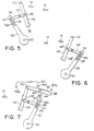
- Figure 3 may be modified to that shown in Figure 6.
- the driven link 32', the movable contactor 42', and the connecting lever 44' and at their final positions are located to be symmetrical with the corresponding components as shown in Figure 5 about a line connecting the axis of the driving shaft 30 to the center of rotation 40.
- a pair of stationary contacts 16bl and 16b2 identical to those shown in Figures 3, 4 and 5 are disposed in symmetrical relationship with the contacts 16al and 16a2 about the same line.
- Figure 6 is quite reverse in operation from that shown in Figures 3, 4 and 5, and therefore the same can provide a contact switching device for the stationary contact 16b as shown in Figure 1 having the switching sequence illustrated in Figure 2B.
- the stationary contacts 16bl and 16b2 form the other half the transfer switch 16 with the movable contactor 42'.
- a pair of connecting links 44 and 44' are pivotally secured at one end to intermediate points equidistant from the center of rotation 40 on the driven links 38 and 38' through pivot pins 46 and 46' respectively and at the other ends to the slide 34 through the pivot pin 48.
- the pair of stationary contacts l6al and 16a2 as shown in Figures 3 and 5 are disposed to be symmetrical with the pair of the stationary contacts 16b2 and l6bl as shown in Figure 6 about a line connecting the axis of the driving shaft 30 to the second center of rotation 40 with the contact l6al connected to the contact 16b2 through a lead 50.
- Figure 7. is formed of that shown in Figure 3 combined with that illustrated in Figure 6 so that the driving link 32, the slide- 34 the compressive spring 36 and the center of rotation 40 are operatively coupled to both the driven links 38 and 38' through the respective connecting links 44 and 44'.
- the driving link 32 is only rotated through a small angle to permit the contacts to be switched in accordance with a switching sequence including the closure followed by the opening and then the opening followed by the closure. Also a contact separating distance is large.
- the present invention can be utilized as various contact switching devices. This is because the guide groove 32a, and the connecting links 44 and 44' can vary in length and the central distances between the center of rotatiun 40 for the driven links 38 and 38' and the pivots 46 and 46' on the connecting links 44 and 44' can vary to change operating points where the contacts are closed and opened, and the contact separating distance and others.
- the present invention can be utilized as a diverter switch for a current carrying contact in a change-over switch for an on-load tap changer or a diverter switch for a tap selector.
- Figure 8A shows one example of such a current carrying contact in a change-over switch.
- the arrangement illustrated comprises a tapped transformer winding 10, an odd-numbered tap 12 connected to the tapped winding 10, an odd-numbered current carrying contact pair 16a connected in series to the tap 12 and in parallel to both an odd-numbered arcing contact pair 20 and a series combination of a resistance contact pair 22 and a current limiting resistor 24, and a parallel combination of an even-numbered arcing contact pair 20' and an even-numbered current carrying contact pair 16b connected to the even-numbered tap 14.
- the contact pairs 16a and 16a and 16b can be formed of the arrangement shown in Figure 7.
- Figure 8B shows a change-over sequence for the arrangement of Figure 8A.
- Figure 9A shows one example of the present invention utilized as a diverter switch for a tap selector.
- a transformer includes a main winding 100 and a tapped winding 110 subsequently connected to a plurality of odd-numbered taps 112a, 112b, 112c, 112d and 112e and also to a plurality of even-numbered taps 114a, 114b, 114c and 114d.
- Those taps are selectively connected to an odd-numbered main contact pair 120 of a change-over switch connected across a series combination of a resistance contact pair and a current limiting resistor.
- the main winding 100 is connected at one end to a stationary contact K of the tap selector subsequently connected to an even-numbered main contact pair 120' of the change-over switch.
- the one end of the main winding 100 is also connected to a first stationary contact 116a of a diverter switch 116 for the tap selector having a second stationary contact 116b. connected to a predetermined point on the main winding 100.
- main contact pairs 120 and 120' and the resistance contact pairs are connected together- to a utilization device (not shown).
- Figure 9B shows a switching sequence for the arrangement of Figure 9A.
Landscapes
- Driving Mechanisms And Operating Circuits Of Arc-Extinguishing High-Tension Switches (AREA)
Abstract
Description
- This invention relates to a contact switching device.
- It is well known, that vacuum switches are advantageous in that the interrupting performance is excellent, contacts are long in lifetime, on.the one hand and disadvantageous in that as the number of current switchings increases, the dielectric strength across the gap is not only decreased but also it becomes unstable, on the other hand. It is also widely known that in on-load tap changers, adjacent taps may have generated thereacross impulse voltages reaching several tens of the normal voltage thereacross.due to lightning strokes invading the mating transformer windings. Therefore with the vacuum switches used as elements for switching currents through on-load tap changers, it is important how the disadvantages of the vacuum switch are compensated for and make the best use of the advantages thereof. Thus these are provided various circuit systems using the diverter switch performing the complicated and special operation.
- Accordingly it is an object of the present invention to provide a new and improved contact switching device which can easily realize a diverter switch required to perform the complicated and special operation.
- The present invention provides a contact switching device comprising a driving link capable of rocking and rotating about a first center of rotation formed of one end thereof, at least one driven link capable of rocking and rotating about a second center of rotation different from the first center of rotation and including a movable contactor, at least one connecting link pivotally secured at one end to the driven link at a point different from the second center of rotation and at the other end to the other end of the driving link to be rockable and rotatable about the other end therefor, and stationary contact means separably engaged by the movable contactor.
- In a preferred embodiment of the present invention, the driving link may include a longitudinally extending guide groove on.the other end portion, a slide slidably disposed within the guide groove and pivotally secured to the other end of the connecting link, and a resilient member disposed within the guide groove tending to push the slide toward the other end of the driving link.
- The present invention will become more readily apparent from the following detailed description taken in conjunction with the accompanying drawings in which:
- Figure 1 is a fragmental circuit diagram of an on-load tap changer;
- Figure 2A is a graph illustrating a switching sequence in which the switches disposed in the arrangement shown in Figure 1 are successively operated with the diversion of a load current effected in one direction;
- Figure 2B is a graph similar to Figure 2A but illustrating a switching sequence for the arrangement shown in Figure 3 with the diversion of the load current effected in the opposite direction;
- Figure 3 is a front plan view of one embodiment according to the contact switching device of the present invention;
- Figure 4 is a view similar to Figure 3 but illustrating an intermediate stage of the arrangement shown in Figure 3 in operation;
- Figure 5 is a view similar to Figure 3 but illustrating the final state in which the arrangement shown in Figure 3 has be completed to be operated;
- Figure 6 is a front plan view of a modification of the present invention in which some components shown in Figure 6 are disposed in symmetric relationship with the same components shown in Figure 3 in the final state;
- Figure 7 is a front plan view of another modification of the present invention in which the arrangement shown in Figure. 3 is operatively associated with that shown in Figure 6.
- Figure 8A is a circuit diagram of an on-load tap changer including the contact switching device of the present invention used as a diverter switch, thereof;
- Figure.8B is a graph illustrating a switching sequence for the arrangement shown in Figure 8A;
- Figure 9A is a diagram similar to Figure 8A but illustrating an on-load tap changer including the contact switching device of the present invention used as a diverter switch of a tap selector; and
- Figure 9B is a graph illustrating a switching sequence for the arrangement shown in Figure 9A.
- Referring now to Figure 1 of the drawings, there is illustrated an on-load tap changer using a plurality of vacuum switches. The arrangement illustrated comprises a tapped
winding 10 of a transformer, an even-numberedtap 12, an odd-numberedtap 14 adjacent to the even-numberedtap 12, a first and a secondstationary contact diverter swtich 16 connected to thetaps stationary contact closure switch 18 connected to thetaps contact pair 20, aresistance contact pair 22 and a current limitingresistor 24 are serially connected to one another in the named order between thediverter switch 16 and the after-closure switch 18 with the junction of thecontact pairs resistance contact pairs - As shown in Figure 1, a series combination of the
contact pairs resistor 24 is connected to the odd-numberedtap 12 through thefirst contact 16a to cause a load current to flow through thattap 12. It is assumed that the utilization device now connected to the odd-numberedtap 12 is changed to be connected to the even-numberedtap 14 through the operations of theswitches resistance contact pairs second diverter contacts closure contacts tap 14 to thetap 12, the current flows through the abovementioned components in accordance with a switching sequence as shown in Figure 2B. In each of Figures 2A and 2B, each row indicates a current flowing through a different one of the abovementioned components designated by the same reference numeral denoting the row. For example, Figure 2A shows that between the end of a flow of current through thecontact 16a and the initiation of a flow of current through thecontact 16b a short pause time interval exists for which no current flows through either thecontact - In the arrangement of Figure 1, the
diverter switch 16 and the after-closure switch 18 are operated to prevent a voltage across thetaps resistance contact pairs resistance contact pairs - In on-load tap changers of the resistance type, the diverter switch includes a quick motion mechanism disposed on a driving shaft for operating the switch to effect a rocking and rotating movement of the driving shaft at a high speed through a predetermined angle. At that time, it is seen from Figures 2A and 2B that the first and second
stationary contacts diverter switch 16 are required to be prevented from being operated during the substantial portion of the rotating movement of the driving shaft through the predetermined angle and also to be opened and closed within a time interval as short as possible respectively and vice versa while at the same time the contact opening operation is required to be as large as possible in order to ensure an electrically insulating distance in excess of that suitable for a voltage across the taps for the short pause time interval as described above. - In order to meet the requirements as described above, the present invention provides a contact switching device comprising a driving link including a longitudinal guide groove radially closed at both ends and rockable and rotatable about a center of rotation formed of one thereof, a slide slidably disposed within the guide groove, a driven link including a movable contactor and rockable and rotatable about a center of rotation different that for the driving link, a connecting link pivotally secured at one end to the driven link at a position different from the second center of rotation and at the other end to the slide, and a resilient member for pushing the slide in a direction of a centrifugal force provided by the driving link or toward the other end of the driving link.
- Referring now to Figure 3 there is illustrated one embodiment according to the contact switching device of the present invention. The arrangement illustrated comprises a
driving shaft 30, and adriving link 32 fixed at one end to thedriving shaft 30. The drivingshaft 30 is arranged to rock and rotate through a predetermined angle to be capable of effect a rocking and rotating movement of thedriving link 32 about the axis of thedriving shaft 30 or a first center of rotation formed of the one end thereof. Also thedriving link 32 is connected to a quick motion mechanism (not shown) and provided on the other end portion with a longitudinally extendingguide groove 32a radially closed at both ends. Then aslide 32 is slidably disposed within theguide groove 32a and pushed toward the other end of thedriving link 32 or in a direction of a centrifugal force provided by thedriving link 32 being rotated by means of a resilient member, in this case, acompressive spring 36 disposed within theguide groove 32a.. - A driven
link 38 is disposed to be rockable and rotatable about a second center ofrotation 40 different from the axis of the drivingshaft 30 or the first center of rotation and has amovable contactor 42 fixed to the free end thereof and provided at both ends with a pair of contact-shaped portions. Also a connectinglink 44 is pivotally secured at one end to an intermediate point on the drivenlink 38 through apivot pin 46 and at the other end to theslide 34 through anotherpivot pin 48. In this way the connectinglink 36 connects thedriving link 32 to the drivenlink 38. - Further Figure 3 shows a pair of spaced stationary contacts 16al and 16a2 supported by supports (not shown) to separably engage both the contact-shaped portions at both ends of the
movable contactor 42 respectively. - The arrangement of Figure 3 is operated as follows: When the
driving shaft 30 is initiated to be rotated in a counterclockwise as viewed in Figure 3 or in the direction of the arrow A shown in Figure 3 to rotate thedriving link 32 in the same direction as thedriving shaft 30, the connectinglink 44 is initiated to be rotated in a clockwise direction as viewed in Figure 3 or the direction of the arrow B shown in Figure 3 about the axis of thepivot pin 46. Simultaneously theslide 34 pivotally secured to the other end of the connectinglink 38 passes through its position where it forms a straight line with axis of thedriving shaft 30, the axes of thepins 48. At that time, theslide 34 is initiated to be moved along theguide groove 32a in a direction of a centrifugal force provided by the rotatingdriving link 32 or in the direction of the arrow C shown in Figure 3. - On the other hand, the
compressive spring 36 imparts a rotational force to the drivenlink 38 through the connectinglink 38 tending to rotate thedriving link 38 in a counterclowise direction as viewed in Figure 3 or in the direction of the arrow D shown in Figure 3 about the second center ofrotation 40. Thus themovable contactor 42 is maintained to be engaged by the stationary contacts 16al and 16a2. - The
driving link 32 is further rotated in the counterclowise direction until theslide 34 reaches that end of the guide groove 33a farthest from thedriving shaft 30 as shown in Figure 4. At that time the drivenlink 38 is inititated to be rotated in a clockwise direction as viewed in Figure 4 or in the direction of the arrow E shown in Figure 4 about the second center ofrotation 42. Thus themovable contactor 42 is disengaged from the stationary contacts l6al and 16a2 resulting in the opening of themovable contactor 42. - When the
driving shaft 32 is further rotated in the counterclockwise direction from its position shown in Figure 4, the drivenlink 38 is rotated in a clockwise direction as viewed in Figure 4 to increase opening distances between themovable contactor 42 and the stationary contacts 16al and 16a2. Thus themovable contactor 42 reaches its final position as shown in Figure 5. - It is now assumed that the clockwise rotational movement of the driving link 21 as described above is effected in a direction to divert the load current from the
tap 12 to thetap 14 as shown in Figures 1 and 2A. Under the assumed conditions, it is seen from the operation as described above in conjunction with Figures 3, 4 and 5 that the arrangement of Figure 3 can provide a contact switching device for the firststationary contact 16a of thediverter switch 16 having the switching sequence illustrated in Figure 2A. In other words the stationary contacts 16al and 16a2 form one half thediverter switch 16 as shown in Figure 1 with themovable contactor 42. - The arrangement of Figure 3 may be modified to that shown in Figure 6. In Figure 6, the driven link 32', the movable contactor 42', and the connecting lever 44' and at their final positions are located to be symmetrical with the corresponding components as shown in Figure 5 about a line connecting the axis of the driving
shaft 30 to the center ofrotation 40. Also a pair of stationary contacts 16bl and 16b2 identical to those shown in Figures 3, 4 and 5 are disposed in symmetrical relationship with the contacts 16al and 16a2 about the same line. - Thus the arrangement of Figure 6 is quite reverse in operation from that shown in Figures 3, 4 and 5, and therefore the same can provide a contact switching device for the
stationary contact 16b as shown in Figure 1 having the switching sequence illustrated in Figure 2B. In other words, the stationary contacts 16bl and 16b2 form the other half thetransfer switch 16 with the movable contactor 42'. - In Figure 7 wherein like reference numerals designate the components identical to those shown in Figures 3 and 6, there is illustrated another modification of the present invention. The arrangement illustrated is different from that shown in Figure 3 only in that in Figure 7 a pair of driven links are operatively coupled to the single driving link through respective connecting links. More specifically, a pair of driven
links 38 and 38' are equal in length to each other and pivotally secured at one end to the second center ofrotation 40 and a pair ofmovable contactors 42 identical to each other are fixed to the free end portions of the drivenlinks 38 and 38' respectively. Also a pair of connectinglinks 44 and 44' are pivotally secured at one end to intermediate points equidistant from the center ofrotation 40 on the drivenlinks 38 and 38' through pivot pins 46 and 46' respectively and at the other ends to theslide 34 through thepivot pin 48. Furthermore the pair of stationary contacts l6al and 16a2 as shown in Figures 3 and 5 are disposed to be symmetrical with the pair of the stationary contacts 16b2 and l6bl as shown in Figure 6 about a line connecting the axis of the drivingshaft 30 to the second center ofrotation 40 with the contact l6al connected to the contact 16b2 through alead 50. - Thus the arrangement of Figure 7.is formed of that shown in Figure 3 combined with that illustrated in Figure 6 so that the driving
link 32, the slide- 34 thecompressive spring 36 and the center ofrotation 40 are operatively coupled to both the drivenlinks 38 and 38' through the respective connectinglinks 44 and 44'. This results in a simpler, more economical and compact structure including a combination of simple mechanical elements such as the links, the springs etc. Furthermore the drivinglink 32 is only rotated through a small angle to permit the contacts to be switched in accordance with a switching sequence including the closure followed by the opening and then the opening followed by the closure. Also a contact separating distance is large. - The present invention can be utilized as various contact switching devices. This is because the
guide groove 32a, and the connectinglinks 44 and 44' can vary in length and the central distances between the center ofrotatiun 40 for the drivenlinks 38 and 38' and thepivots 46 and 46' on the connectinglinks 44 and 44' can vary to change operating points where the contacts are closed and opened, and the contact separating distance and others. - For example, the present invention can be utilized as a diverter switch for a current carrying contact in a change-over switch for an on-load tap changer or a diverter switch for a tap selector. Figure 8A shows one example of such a current carrying contact in a change-over switch. The arrangement illustrated comprises a tapped transformer winding 10, an odd-numbered
tap 12 connected to the tapped winding 10, an odd-numbered current carryingcontact pair 16a connected in series to thetap 12 and in parallel to both an odd-numberedarcing contact pair 20 and a series combination of aresistance contact pair 22 and a current limitingresistor 24, and a parallel combination of an even-numbered arcing contact pair 20' and an even-numbered current carryingcontact pair 16b connected to the even-numberedtap 14. - The contact pairs 16a and 16a and 16b can be formed of the arrangement shown in Figure 7.
- Figure 8B shows a change-over sequence for the arrangement of Figure 8A.
- Figure 9A shows one example of the present invention utilized as a diverter switch for a tap selector. In Figure 9A a transformer includes a main winding 100 and a tapped winding 110 subsequently connected to a plurality of odd-numbered
taps taps main contact pair 120 of a change-over switch connected across a series combination of a resistance contact pair and a current limiting resistor. The main winding 100 is connected at one end to a stationary contact K of the tap selector subsequently connected to an even-numbered main contact pair 120' of the change-over switch. The one end of the main winding 100 is also connected to a first stationary contact 116a of adiverter switch 116 for the tap selector having a secondstationary contact 116b. connected to a predetermined point on the main winding 100. Then main contact pairs 120 and 120' and the resistance contact pairs are connected together- to a utilization device (not shown). - Figure 9B shows a switching sequence for the arrangement of Figure 9A.
- The present invention has the following advantages:
- 1) A contact switching mechanism can be provided in which the driving side is rotated through a small angle to permit the switching operation to be performed in the order of the closure, the opening, and the closure and a contact separating distance is large.
- 2) Various contact switching devices can be provided by changing dimensions of the structural elements.
- 3) The contact switching devices set forth in the above sections 1) and 2) can be realized by combinating a small number of mechanical elements such as a spring, links etc.
- 4) The contacts are small in mechanical wear because the contact switching device is of the butt type.
- While the present invention has been illustrated and described in conjunction with a few preferred embodiments thereof it is to be understood that numerous changes and modifications may be resorted to without departing the spirit and scope of the present invention.
Claims (5)
Applications Claiming Priority (2)
| Application Number | Priority Date | Filing Date | Title |
|---|---|---|---|
| JP141468/82 | 1982-08-12 | ||
| JP57141468A JPS5931526A (en) | 1982-08-12 | 1982-08-12 | Device for switching contactor |
Publications (2)
| Publication Number | Publication Date |
|---|---|
| EP0103413A1 true EP0103413A1 (en) | 1984-03-21 |
| EP0103413B1 EP0103413B1 (en) | 1986-12-03 |
Family
ID=15292580
Family Applications (1)
| Application Number | Title | Priority Date | Filing Date |
|---|---|---|---|
| EP83304680A Expired EP0103413B1 (en) | 1982-08-12 | 1983-08-12 | Contact switching device |
Country Status (4)
| Country | Link |
|---|---|
| US (1) | US4472615A (en) |
| EP (1) | EP0103413B1 (en) |
| JP (1) | JPS5931526A (en) |
| DE (1) | DE3368147D1 (en) |
Cited By (3)
| Publication number | Priority date | Publication date | Assignee | Title |
|---|---|---|---|---|
| US4736114A (en) * | 1985-02-23 | 1988-04-05 | Sachsenwerk Licht- Und Kraft-Aktiengesellshaft | Electrical switching system and method to switch this system |
| CN105679565A (en) * | 2014-11-20 | 2016-06-15 | 施耐德电气工业公司 | Automatic conversion mechanism, automatic conversion switch, and manufacturing method for automatic conversion mechanism |
| CN109216068A (en) * | 2017-07-06 | 2019-01-15 | 施耐德电器工业公司 | Automatic change-over |
Families Citing this family (5)
| Publication number | Priority date | Publication date | Assignee | Title |
|---|---|---|---|---|
| US5140117A (en) * | 1991-02-28 | 1992-08-18 | Pmc Engineering Company, Inc. | Two-link, trip-free mechanism for use in a switch assembly |
| US5693922A (en) * | 1995-11-13 | 1997-12-02 | Abb Power T&D Company Inc. | Diverter switch and link system for load tap changer |
| CN101188167B (en) * | 2007-11-30 | 2010-10-06 | 赵建清 | Buffer drive pole device |
| EP2831898B1 (en) * | 2012-03-30 | 2016-03-30 | ABB Technology Ltd. | Electrical circuit switch |
| US10083809B2 (en) * | 2016-04-21 | 2018-09-25 | Hartland Controls, Llc | Electrical power transfer switch |
Citations (4)
| Publication number | Priority date | Publication date | Assignee | Title |
|---|---|---|---|---|
| US1460542A (en) * | 1923-07-03 | Switch | ||
| DE1187292B (en) * | 1961-11-30 | 1965-02-18 | Sachsenwerk Licht & Kraft Ag | Multipole high-voltage disconnector |
| DE1515680A1 (en) * | 1965-09-02 | 1969-11-13 | Elektronisches Werk Fritz Drie | Device for driving the moving contacts of high-voltage switch disconnectors and the like. |
| US3632908A (en) * | 1969-06-18 | 1972-01-04 | Reinhausen Maschf Scheubeck | Regulating transformer tap-changer switch |
Family Cites Families (6)
| Publication number | Priority date | Publication date | Assignee | Title |
|---|---|---|---|---|
| US320017A (en) * | 1885-06-16 | Cut-out for electric circuits | ||
| US2601422A (en) * | 1947-01-07 | 1952-06-24 | Ite Circuit Breaker Ltd | Circuit breaker |
| US3013143A (en) * | 1960-10-24 | 1961-12-12 | Hayden Stephen | Welding contactor |
| US3264420A (en) * | 1964-07-01 | 1966-08-02 | Gen Electric | Cable grounding, three position, snap action switch |
| JPS6055933B2 (en) * | 1978-07-19 | 1985-12-07 | 三菱電機株式会社 | Fast-acting mechanism for load disconnector |
| JPS5753027A (en) * | 1980-09-16 | 1982-03-29 | Mitsubishi Electric Corp | Mechanism for energizing on-load tap changer |
-
1982
- 1982-08-12 JP JP57141468A patent/JPS5931526A/en active Granted
-
1983
- 1983-08-12 DE DE8383304680T patent/DE3368147D1/en not_active Expired
- 1983-08-12 EP EP83304680A patent/EP0103413B1/en not_active Expired
- 1983-08-12 US US06/522,731 patent/US4472615A/en not_active Expired - Lifetime
Patent Citations (4)
| Publication number | Priority date | Publication date | Assignee | Title |
|---|---|---|---|---|
| US1460542A (en) * | 1923-07-03 | Switch | ||
| DE1187292B (en) * | 1961-11-30 | 1965-02-18 | Sachsenwerk Licht & Kraft Ag | Multipole high-voltage disconnector |
| DE1515680A1 (en) * | 1965-09-02 | 1969-11-13 | Elektronisches Werk Fritz Drie | Device for driving the moving contacts of high-voltage switch disconnectors and the like. |
| US3632908A (en) * | 1969-06-18 | 1972-01-04 | Reinhausen Maschf Scheubeck | Regulating transformer tap-changer switch |
Non-Patent Citations (1)
| Title |
|---|
| Patent Abstracts of Japan vol. 3, no. 159, 27 December 1979 page 4E162 & JP-A-54 139022 * |
Cited By (5)
| Publication number | Priority date | Publication date | Assignee | Title |
|---|---|---|---|---|
| US4736114A (en) * | 1985-02-23 | 1988-04-05 | Sachsenwerk Licht- Und Kraft-Aktiengesellshaft | Electrical switching system and method to switch this system |
| CN105679565A (en) * | 2014-11-20 | 2016-06-15 | 施耐德电气工业公司 | Automatic conversion mechanism, automatic conversion switch, and manufacturing method for automatic conversion mechanism |
| CN105679565B (en) * | 2014-11-20 | 2019-02-15 | 施耐德电气工业公司 | Automatic transfer mechanism, automatic transfer switch and method of making the same |
| CN109216068A (en) * | 2017-07-06 | 2019-01-15 | 施耐德电器工业公司 | Automatic change-over |
| CN109216068B (en) * | 2017-07-06 | 2019-12-03 | 施耐德电器工业公司 | automatic transfer switch |
Also Published As
| Publication number | Publication date |
|---|---|
| JPH0254611B2 (en) | 1990-11-22 |
| DE3368147D1 (en) | 1987-01-15 |
| JPS5931526A (en) | 1984-02-20 |
| EP0103413B1 (en) | 1986-12-03 |
| US4472615A (en) | 1984-09-18 |
Similar Documents
| Publication | Publication Date | Title |
|---|---|---|
| KR100248253B1 (en) | Switching arrangement for load change-over switches of step switches and for selector switches | |
| US3590175A (en) | Composite selector switch and reversing switch for tap-changing regulating transformers | |
| JPH03500224A (en) | thyristor conversion switch | |
| CN112071672B (en) | Vacuum on-load tap-changer transition device and switching method of transition device | |
| EP0103413A1 (en) | Contact switching device | |
| JP2022536704A (en) | on-load tap changer | |
| JPH11191514A (en) | On-load tap changer | |
| US10373771B2 (en) | Tap-changer switching system and method of operating same | |
| US3250865A (en) | Transfer switch for tapped regulating transformers with radial guide and linkage structure | |
| HU182971B (en) | Vacuum space ratio switch for tapped transformars | |
| US5693922A (en) | Diverter switch and link system for load tap changer | |
| EP3758035B1 (en) | Single-phase diverter switch for column-type on-load tap changer | |
| US3194900A (en) | Modular tap-changing selector switch for connecting selectively fixed tap contacts to a transfer switch | |
| US3415957A (en) | Transfer switch for tap-changing regulating transformers having current-carrying contacts and operating means therefor achieving high initial speeds of contact separation | |
| JPS586295B2 (en) | Switching switch for tap changer on load | |
| US3671687A (en) | Transfer switch for tap-changing regulating transformers including lost motion interconnection driving mechanism | |
| US3258546A (en) | Transfer switch with movable contact toggle mechanism for tapped regulating transformers | |
| EP0113953B1 (en) | On-load tap changer with vacuum switches | |
| WO2015044361A1 (en) | Tap changer for a transformer | |
| US3400231A (en) | Transfer switch for tap-changing transformers having contacts movable along orthogonal diameters of a circle | |
| US5773970A (en) | Tap changer with tickler coil for arcless tap changing | |
| US3238320A (en) | Transfer switch for tap changers for regulating transformers including a cylindrical insulating housing, a squirrel-cage contact-supporting structure and contact bridgesinsulatingly supported by contact bridge carriers | |
| EP4629273A1 (en) | Static contact unit, contact system and tap changer | |
| ES292579A1 (en) | Opposite rotational sense actuator mechanism for tap changer contacts | |
| US3312793A (en) | Tap changer with sequential contact actuating means |
Legal Events
| Date | Code | Title | Description |
|---|---|---|---|
| PUAI | Public reference made under article 153(3) epc to a published international application that has entered the european phase |
Free format text: ORIGINAL CODE: 0009012 |
|
| AK | Designated contracting states |
Designated state(s): BE DE GB |
|
| 17P | Request for examination filed |
Effective date: 19840706 |
|
| GRAA | (expected) grant |
Free format text: ORIGINAL CODE: 0009210 |
|
| AK | Designated contracting states |
Kind code of ref document: B1 Designated state(s): BE DE GB |
|
| REF | Corresponds to: |
Ref document number: 3368147 Country of ref document: DE Date of ref document: 19870115 |
|
| PLBE | No opposition filed within time limit |
Free format text: ORIGINAL CODE: 0009261 |
|
| STAA | Information on the status of an ep patent application or granted ep patent |
Free format text: STATUS: NO OPPOSITION FILED WITHIN TIME LIMIT |
|
| 26N | No opposition filed | ||
| PG25 | Lapsed in a contracting state [announced via postgrant information from national office to epo] |
Ref country code: BE Effective date: 19890831 |
|
| BERE | Be: lapsed |
Owner name: MITSUBISHI DENKI K.K. Effective date: 19890831 |
|
| PGFP | Annual fee paid to national office [announced via postgrant information from national office to epo] |
Ref country code: GB Payment date: 19910805 Year of fee payment: 9 |
|
| PGFP | Annual fee paid to national office [announced via postgrant information from national office to epo] |
Ref country code: DE Payment date: 19910930 Year of fee payment: 9 |
|
| PG25 | Lapsed in a contracting state [announced via postgrant information from national office to epo] |
Ref country code: GB Effective date: 19920812 |
|
| GBPC | Gb: european patent ceased through non-payment of renewal fee |
Effective date: 19920812 |
|
| PG25 | Lapsed in a contracting state [announced via postgrant information from national office to epo] |
Ref country code: DE Effective date: 19930501 |