-
This invention relates to an on-load tap changer, and more particularly to an on-load tap changer which employs resistors as current-limiting bridge elements.
-
A known on-load tap changer of this type is shown in Figure 1 of the accompanying drawings. The tap selecting arms 1 and 2 of a tap selector for respectively selecting the odd-numbered side tap and even-numbered side tap of a transformer adjusting winding T are connected to the winding. An odd-numbered side input terminal 3 and even-numbered side input terminal 4 are respectively connected to the tap selecting arms 1 and 2. An odd-numbered side main switch A and even-numbered side main switch B are respectively connected to the input terminals 3 and 4. The respective main switches are constructed of stationary contacts 5, 6, and movable contacts 7. 8 adapted to come into and out of contact with the stationary contacts 5, 6. Current-limiting resistors Rl, R2 are connected in parallel with the respective main switches A, B, and electric paths are changed so that load currents may flow through the current-limiting resistors Rl, R2 when the main switches are opened. In addition, an odd-numbered side auxiliary switch C and even-numbered side auxiliary switch D are connected to a common output terminal 13. The respective auxiliary switches are constructed of stationary contacts 9, 10 connected to the corresponding movable contacts 7, 8, and movable contacts 11, 12 adapted to come into and out of contact with the corresponding stationary contacts 9, 10.
-
Figure 1 illustrates the state in which the
movable contacts 7 and 11 are respectively engaged with
stationary contacts 5 and 9. so that the load current is conducted by the odd-numbered side tap to pass along the path
from the transformer adjusting winding T.
-
The principle of a tap change operation in the case of changing from this state to an even-numbered tap will be described with reference to the operating sequence illustrated in Figure 2. Symbols in this figure correspond tc those in Figure 1.
-
i First, when the movable contact 7 of the main switch A is disengaged from the
stationary contact 5, the load current is supplied via the current path
-
Secondly, when the
movable contact 12 of the even-numbered side auxiliary switch D is engaged with the
stationary contact 10, the load current is divided in two and is supplied via the current path
and the current path
Further, an inter-tap circulating current flows through the current path
-
Subsequently, when the
movable contact 11 of the odd-numbered side auxiliary switch C is disengaged from the
stationary contact 9, the load current is supplied by the current path
-
Next, when the movable contact 8 of the even-numbered main switch B is engaged with the
stationary contact 6, the load current is supplied by the current path
The change from the odd-numbered tap to the even-numbered tap is now complete.
-
To change to an odd-numbered tap again, the reverse operation to the above change operation is carried out, and the current conducting sequence is exactly the reverse relationship to the case of the above change. (This is called the "electrical reversible relationship".)
-
As described above, with the prior-art device shown in Figure 1, even if the main switch A or B fails to interrupt the current in the course of the tap change, the auxiliary switch C or D which is connected in series with the corresponding main switch and which is opened later than the corresponding main switch effects backup interruption, so that the reliability of the tap change is enhanced. In addition, if an abnormal voltage appears on the transformer adjusting winding T into the side which is open-circuited by the main switch A or B and the auxiliary switch C or D, dielectric breakdown takes place between the
movable contact 11 or 12 and the respective
stationary contact 9 or 10 of the auxiliary switches C or D. (Since the main switch A or B has the current-limiting resistor Rl or R2 connected in parallel therewith, its terminal voltage becomes equal to the voltage across the resistor. Accordingly, no dielectric breakdown takes place in the main switch.) This brings the advantage that, even when the abnormal voltage tends to form a short-circuit


there is no inter-tap short-circuit of the transformer adjusting winding T, owing to the insertion of the current-limiting resistor Rl or R2. Meanwhile, since the mechanism is so constructed as to drive the movable contact of each switch without interposing any insulator, or the switching drive mechanism is held at the potential of the output terminal. That is, the switching drive mechanism is held at the output terminal potential in order to simplify the construction of the device by dispensing with an insulator. Since, in this case, the main switches A and B are located on the input terminal side and have the current-limiting resistors connected in parallel therewith, the inter-tap voltage of the transformer winding is applied across the main switch at all times. This leads to the disadvantage that the switching drive mechanism of the main switch must be sufficiently insulated.
-
An object of this invention is to eliminate the disadvantage of the prior art as stated above, without losing the advantages thereof. According to the invention, main switches on an odd-numbered side and an even-numbered side, and current-limiting resistors connected in parallel therewith, are disposed on the output terminal side, while the auxiliary switches are disposed on the input terminal or tap selector side. The stationary contacts of the main switches and auxiliary switches are arrayed on the input terminal side, with the movable contact thereof being arrayed on the output terminal side: and the tap selectors and the stationary contacts of the auxiliary switches, the movable contacts of the auxiliary switches and the stationary contacts of the main switches, and the movable contacts of the main switches and an output terminal, are respectively connected. Thus, an inter-tap voltage acts on the movable contact of the auxiliary switch only midway of the tap change. The invention accordingly provides an on-load tap changer which is highly reliable in insulation and in which no inter-tap voltage acts on the movable contacts of the main and auxiliary switches no matter which of the odd-numbered side or the even-numbered side is closed to execute a steady operation.
-
Embodiments of the invention are shown in Figs. 3 and 4 of the accompanying drawings, in which:
- Figure 2 is an operating sequence diagram of a device according to the present invention:
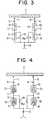
- Figure 3 is a connection diagram of an embodiment of this invention: and
- Figure 4 is a connection diagram of another embodiment of this invention.
-
In the drawings, the same symbols indicate the same of corresponding parts.
-
In Figure 3, the same parts as in Figure 1 are assigned the same symbols, and the parts will not be explained again. In the illustrated embodiment, odd-and even-numbered side main switches A, B and current-limiting resistors Rl, R2 connected in parallel therewith are connected to the common output terminal 31, while odd-numbered and even-numbered side auxiliary switches C, D are connected to the input terminals 3, 4. The stationary contacts 5, 6, 9, 10 of the main and auxiliary switches A, B, C, D are arrayed closer to the input terminals 3, 4, (i.e. the live side) while the movable contacts 7, 8. 11, 12 are arrayed closer to the output terminal 13. Tap selecting arms 1, 2 are connected to the stationary contacts 9, 10; the movable contacts 11, 12 are connected to the stationary contacts 5, 6; and the movable contacts 7. 8 are connected to the output terminal 13. The operations and effects of the device will be described below.
-
Figure 3 illustrates the state of steady operation with an odd-numbered tap, in which the movable contact 7 of the odd-numbered side main switch A and the
movable contact 11 of the odd-numbered side auxiliary switch C are respectively engaged with the
stationary contact 5 of the main switch A and the
stationary contact 9 of the auxiliary switch C, respectively, so that a load current flows from the transformer adjusting winding T through the current path
At this time, the
movable contacts 7, 8, 11 are at the potential of the output terminal, and also the
movable contact 12 of the "even" auxiliary switch is at the output potential through the current-limiting resistor R2.
-
The operating principle of changing from this state to the even-numbered tap will be described with reference to the operating sequence of Figure 2. First, when the movable contact 7 of the odd-numbered side main switch A is disengaged from its
stationary contact 5, the load current is supplied via the current path
At this time, a voltage drop component based on the load current flowing through the current-limiting resistor Rl, namely, an inter-tap voltage develops across the
movable contact 11.
-
Subsequently, when the
movable contact 12 of the even-numbered auxiliary switch D is thrown on its
stationary contact 10, the load current is divided in two and is supplied by the current paths
and
Further, a circulating current flows through the current path
-
At this time, voltage corresponding to the voltage drops of the respective current-limiting resistors Rl and R2 based on the superposed components of the divided load currents and the circulating current act on the movable contact 11 and 12.
-
Next. when the
movable contact 11 of the odd-numbered side auxiliary switch C is disengaged from the
stationary contact 9, the load current is supplied by the current path :
At this time, a voltage corresponding to the voltage drop of the current-limiting resistor R2 based on the load current acts on the
movable contact 12.
-
Next, when the movable contact 8 of the even-numbered side main switch B is engaged with the
stationary contact 6. the load current is supplied by the current path
Then, the change from the odd-numbered tap to the even-numbered tap is complete, and the state of steady operation with the even-numbered side tap is established. At this time, the
movable contacts 7, 8, 12 are at the potential of the
output terminal 13 and also the
movable contact 11 is at the output terminal potential through the current-limiting resistor Rl.
-
In case of changing from this state to the odd-numbered side again, the reverse operation is performed owing to the electrical reversible relationship.
-
As will be understood from the operations described above in detail, even when the main switch A or B has failed in current interruption in the process of the tap change operation, the auxiliary switch C or D which is connected in series with the corresponding main switch and which is opened later than the corresponding main switch executes backup interruption. Therefore, the reliability of the tap change is enhanced. In addition, if an abnormal voltage appears on the transformer adjusting winding T into the side which is open-circuited by the main switch A or B and the auxiliary switch C or D, dielectric breakdown takes place between the
movable contact 11 or 12 and the respective
stationary contact 9 or 10 of the auxiliary switch C or D; since the movable contact 7 or 8 and the
stationary contact 5 or 6 of the main switch A or B are connected by the current-limiting resistor Rl or R2, they become equipotential, and no dielectric breakdown occurs therebetween. Thus. the device of the invention keeps intact the advantage of the prior-art device that even when the abnormal voltage tends to form a short-circuit
or
there is no inter-tap short-circuit, owing to the insertion of the current-limiting resistor Rl or R2 Furthermore, the movable contacts of the main and auxiliary switches on the side which is closed in the steady operation state and the movable contact of the main switch on the opened side lie, of course, at the output terminal potential, and also the movable contact of the auxiliary switch on the opened side attains the output terminal potential through the current-limiting resistor, so that all of the four
movable contacts 7, 8, 11, 12 can be held at the output terminal potential.
-
Accordingly, if the movable contacts are driven by switching drive mechanisms which are set at the output terminal potential, the movable contacts of the two auxiliary switches located on the input terminal sides are driven through insulators, but unlike the prior-art device, the insulators have voltages applied thereto only during the transient period of the tap change and have no voltage applied thereto during the steady operation. This adds the advantage that the reliability of insulation is sharply enhanced.
-
Figure 4 shows another embodiment, in which vacuum switches A1, Bl and Cl, Dl are respectively employed as the main switches A, B and auxiliary switches C, D in Figure 3, and which achieves similar effects.
-
As set forth above, this invention has the effect of remarkably enhancing the reliability of tap change by a simple construction.


 Further, an inter-tap circulating current flows through the current path


 Further, a circulating current flows through the current path


 there is no inter-tap short-circuit, owing to the insertion of the current-limiting resistor Rl or R2 Furthermore, the movable contacts of the main and auxiliary switches on the side which is closed in the steady operation state and the movable contact of the main switch on the opened side lie, of course, at the output terminal potential, and also the movable contact of the auxiliary switch on the opened side attains the output terminal potential through the current-limiting resistor, so that all of the four