EP0103209A2 - Improvements in tabletting machines - Google Patents
Improvements in tabletting machines Download PDFInfo
- Publication number
- EP0103209A2 EP0103209A2 EP83108183A EP83108183A EP0103209A2 EP 0103209 A2 EP0103209 A2 EP 0103209A2 EP 83108183 A EP83108183 A EP 83108183A EP 83108183 A EP83108183 A EP 83108183A EP 0103209 A2 EP0103209 A2 EP 0103209A2
- Authority
- EP
- European Patent Office
- Prior art keywords
- punch
- punches
- die
- dies
- radially outer
- Prior art date
- Legal status (The legal status is an assumption and is not a legal conclusion. Google has not performed a legal analysis and makes no representation as to the accuracy of the status listed.)
- Granted
Links
Images

Classifications
-
- B—PERFORMING OPERATIONS; TRANSPORTING
- B30—PRESSES
- B30B—PRESSES IN GENERAL
- B30B11/00—Presses specially adapted for forming shaped articles from material in particulate or plastic state, e.g. briquetting presses, tabletting presses
- B30B11/02—Presses specially adapted for forming shaped articles from material in particulate or plastic state, e.g. briquetting presses, tabletting presses using a ram exerting pressure on the material in a moulding space
- B30B11/12—Presses specially adapted for forming shaped articles from material in particulate or plastic state, e.g. briquetting presses, tabletting presses using a ram exerting pressure on the material in a moulding space co-operating with moulds on the circumference of a rotating drum
-
- B—PERFORMING OPERATIONS; TRANSPORTING
- B30—PRESSES
- B30B—PRESSES IN GENERAL
- B30B11/00—Presses specially adapted for forming shaped articles from material in particulate or plastic state, e.g. briquetting presses, tabletting presses
- B30B11/02—Presses specially adapted for forming shaped articles from material in particulate or plastic state, e.g. briquetting presses, tabletting presses using a ram exerting pressure on the material in a moulding space
- B30B11/025—Presses specially adapted for forming shaped articles from material in particulate or plastic state, e.g. briquetting presses, tabletting presses using a ram exerting pressure on the material in a moulding space whereby the material is transferred into the press chamber by relative movement between a ram and the press chamber
-
- B—PERFORMING OPERATIONS; TRANSPORTING
- B30—PRESSES
- B30B—PRESSES IN GENERAL
- B30B15/00—Details of, or accessories for, presses; Auxiliary measures in connection with pressing
- B30B15/0082—Dust eliminating means; Mould or press ram cleaning means
-
- Y—GENERAL TAGGING OF NEW TECHNOLOGICAL DEVELOPMENTS; GENERAL TAGGING OF CROSS-SECTIONAL TECHNOLOGIES SPANNING OVER SEVERAL SECTIONS OF THE IPC; TECHNICAL SUBJECTS COVERED BY FORMER USPC CROSS-REFERENCE ART COLLECTIONS [XRACs] AND DIGESTS
- Y10—TECHNICAL SUBJECTS COVERED BY FORMER USPC
- Y10S—TECHNICAL SUBJECTS COVERED BY FORMER USPC CROSS-REFERENCE ART COLLECTIONS [XRACs] AND DIGESTS
- Y10S425/00—Plastic article or earthenware shaping or treating: apparatus
- Y10S425/035—Opposed plunger
Definitions
- Fig. 7 also shows an annular safety plate 141 secured to the top surface of the outer turret 25.
- the plate 141 has a cylindrical lip 142 at its outer edge which projects downwards and prevents the cups 50, and . thus the outer punches 16, from leaving the turret 25 should the restraining influence of the hoop 52 be removed due to breakage.
- the safety plate 141 is only effective in an emergency and normally makes no contact with the moving parts of the outer punch assembly.
- the punches 16 have their radially inner ends slidably supported and operating permanently in the dies 40, and rotatable therein to satisfy the requirement of shaped tooling, that is to say, punches and dies of elongated or asymmetrical shape in cross-section.
- the outer punches 16 are slidably supported towards both ends and are rotatable to accommodate their cross- sectional shape to that of the dies whenever necessary.
Landscapes
- Engineering & Computer Science (AREA)
- Mechanical Engineering (AREA)
- Medical Preparation Storing Or Oral Administration Devices (AREA)
Abstract
Description
- This invention relates to tabletting machines and concerns tabletting machines of the kind (hereinafter referred to as of the kind described) in which the powdered or granulated material to be tabletted is fed onto the surface of a rotating die table so as to fill dies in the die table and be compressed into a tablet in each die between a pair of punches, one of the punches being subsequently withdrawn from the die and the other punch being pushed through the die to eject the tablet from the die.
- In a conventional tabletting machine of the kind described, the die table is horizontally disposed and individual pairs of punches operate vertically to enter the dies from opposite ends, the punches being operated by stationary cams. Means is provided for adjusting the cams thereby to adjust the amount of material which is compressed in each die to form each tablet and the thickness of the resulting tablet.
- In our British Patents Nos. 1,481,797 and 1,481,798 we describe a tabletting machine of the kind described having a continuous, adjustable cam track to operate radially outer punches, there being radially inner and outer punches operating radially with respect to the axis of rotation of a concave cylindrically surfaced die table. The use of a continuous, adjustable cam track avoids noise and wear problems encountered in conventional tabletting machines. The use of a cylindrical die table having a concave cylindrical surface has the advantage that powdered or granulated material to be tabletted moves from the surface of the die table into the dies with the assistance of centrifugal force so that feeding of the material to be tabletted, into the dies, is improved.
- A problem which arises with tabletting machines in general is that relatively movable bearing surfaces of the machine are liable to contamination and wear by the material being tabletted. This is particularly true of the sliding bearing surfaces of the punches and the punch guides which require to be positioned adjacent the die table.
- An object of the present invention is to reduce or eliminate this problem more particularly, although not exclusively, in a tabletting machine in which the punches operate radially of the axis of rotation of the die table.
- As regards radially outer punches, in a tabletting machine of the present invention, the use of sliding bearings cannot be avoided but space is available to deal with the problem of preventing contamination of these bearings. Furthermore, the solution to this problem is applicable generally to the problem of preventing contamination of the sliding bearing surfaces of the punches and the punch guides in conventional tabletting machines of the kind described.
- According to the present invention a tabletting machine of the kind described has reciprocating punches slidably supported at one end and pump means is provided, individual to each reciprocating punch and operated with the punch to force air through an annular gap defined about the punch by a sealing sleeve surrounding an intermediate portion of the punch each time the punch is stroked in one direction.
- Preferably the individual pump means rotate with the reciprocating punch and the support means therefor about the axis of rotation of the die table.
- The provision of individual pump means rotating with the reciprocating punches to provide air seals protecting the sliding bearing surfaces of the punches obviates the complication of supplying compressed air from a remote source to a rotating part.
- A tabletting machine of the kind described and embodying the present invention as defined above will now be described by way of example, and not by way of limitation, with respect to the accompanying drawings in which :-
- Fig. 1 is a plan view of the cabinet top on which various parts of the machine are mounted;
- Fig. 2 is a plan view of a feeder plate for feeding powdered or granulated material to be tabletted onto the surface of a die table;
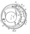
- Fig. 3 is a plan view of elements of the machine positioned under the feeding arrangement;
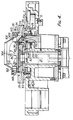
- Fig. 4 is a cross-section through the top of the cabinet taken along line A-A of Fig. 3 and with a cover in position;
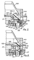
- Fig. 5 is a section taken along line B-B of Fig. 3;
- Fig. 6 is a section taken along line C-C of Fig. 3;
- Fig. 7 is a partial view in cross-section showing a pair of co-operating, radially inner and outer punches in a die, the radially inner punch being shown at its point of maximum penetration into the die;
- Fig. 8 shows a detail of Fig. 7;
- Fig. 9 is a side view, partially in cross-section, the direction F corresponding to that in Fig. 3, showing more of the arrangement for feeding the powdered or granulated material to be tabletted onto the surface of the die table; and
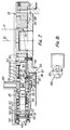
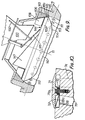
- Fig. 10 is a partial view in cross-section showing a further detail of the machine.
- With reference now to the accompanying drawings, and first to Fig. 1, the parallel axes of rotation of an inner hub and an outer turret of the machine are indicated respectively at 10 and 11. Three equi-spaced
turret support rollers axis 11. A pair of tabletweight adjustment rollers 54, a pressure roller 56, for adjusting tablet thickness, and anejection roller 58 constrain a flexible band or hoop 52 in a tri-lobe shape to control the movements of radially outer punches 16 (see Fig. 7). The operation of the hoop 52, which rotates with the turret about its own axis of rotation, and the adjustments for tablet weight and tablet thickness are as described in our British Patents Nos. 1,481,797 and 1,481,798 with reference to the corresponding parts of the machine described in the specifications of these patents, and there being one tablet produced in each die per revolution of the outer turret. Fig. 1 also shows anarcuate member 20 in the cabinet top comprising a tablet take-off passage 20'and a separatedust extraction passage 20" - Referring now to Figs. 2 to 6 and in particular to Fig. 4, the inner hub is indicated at 23 and the outer turret at 25. The
rollers peripheral groove 26 in aturret support ring 27 having internalinvolute teeth 28 engaged by involuteteeth 29 on apinion 30. Thepinion 30 is mounted on a step on the top end face of a vertically extendingmain drive shaft 31 and drives theturret support ring 27. The outer turret further comprises a die table in the form of aring 33 and is bolted to theturret support ring 27 concentric therewith, the inner concave surface of thering 33 forming the die table surface and being divided by anannular step 34 into an uppercylindrical surface portion 36 having its cylindrical axis lying along theaxis 11 and a lower-partspherical surface portion 38 having its centre of curvature at 39 (see Fig. 7) on theaxis 11. - Referring to Fig. 7 the
dies 40 are separately formed each being made up of a cylindrical body having a part-spherical, radially inner end face 41 lying flush with thesurface portion 38 and centred at 39, the die bodies being locked inradial bores 43 in thedie table ring 33 and seated againststeps 44 therein, the axes of thebores 43 and thedies 40 all lying in a common plane normal to theaxis 11. - The radially
outer punches 16 are slidably supported and movable inflanged sleeves 46 positioned in thebores 43 with theirflanges 47 abutting afurther step 48 therein. At their radially outer ends thepunches 16 carry guides in the form ofcups 50, thepunches 16 being rotatable in the cups and thecups 50 abutting the underside of the punch heads 51. Thecups 50 slide in the radially outer ends of thebores 43, there being an open coiledcompression spring 60 engaged between each cup and theflange 47 of its associated sleeve and urging apressure pad 61 having a stem 62 rotatably received in abore 63 in the punch, and being itself rotatably restrained in atransverse slot 64 formed in the bottom of the cup, against the inner surface of the hoop 52. The hoop 52 is received and guided by theslots 64 and thepads 61 have radiused outer surfaces 65 (see Fig. 8) to slidably engage the inner surface of the hoop. - At the radially outermost end of each of the
cups 50 are fastened two safety dogs or restrainingelements 140. The function of thesesafety dogs 140 is to ensure that theouter punches 16 complete their outward strokes even in the event of abroken spring 60 or a tightouter punch 16, so preventing damage when aninner punch 83 enters thedie 40. Thedogs 140 do not make contact with the radially outer circumferential surface of hoop 52 during normal running and only become effective in.an emergency. - Fig. 7 also shows an
annular safety plate 141 secured to the top surface of theouter turret 25. Theplate 141 has acylindrical lip 142 at its outer edge which projects downwards and prevents thecups 50, and . thus theouter punches 16, from leaving theturret 25 should the restraining influence of the hoop 52 be removed due to breakage. As in the case of thesafety dogs 140, thesafety plate 141 is only effective in an emergency and normally makes no contact with the moving parts of the outer punch assembly. - Referring to Fig. 10 plastics film one-
way flap valves 66 having angled opening- limiting metal backing plates 66a are provided, each one of which is associated with twoadjacent bores 43 to allow air to be sucked into thecylinder spaces 68 formed between thesealing sleeves 46 and theguides 50 when theguides 50 move radially outwardly in thebores 43, such air being expelled along the narrow annular gaps between the inner surfaces of thesleeves 46 and the outer surfaces of thepunches 16, thereby to prevent the entry of powdered material being tabletted into thespaces 68 and thus protecting from contamination the sliding bearing surfaces of the outer punches, formed between thecups 50 and thebores 43, when theguides 50 move radially inwardly in thebores 43. Alternatively, an individual flap valve can be associated with eachbore 43. Theguide 50 andsealing sleeve 46 associated with eachpunch 16 form with thepunch 16 and its associated bore 43 a pump means individual to thepunch 16 which rotates around the axis ofrotation 11 with, and which is operated with the punch to force sealing air between the sealing sleeves and the punch each time the punch is stroked in the radially inward direction. - The
flap valves 66 are positioned inpockets 72 in the upwardly facing surface 69 of theturret 25, outwardly of an upstanding portion of theturret comprising ring 33 and defining thesurface portion 36 and each comprises a plastics film disc and a metal disc fastened eccentrically by an '0' ring seal 70 beneath arigid cover 71 for the pocket, held in place by a screw 71a. Thepockets 72 communicate throughbores 73 controlled by the flap valves with the underside of theturret 25 in a clean air zone sealed from penetration by material being tabletted and the flap valves, when open, communicate thebores 73 each with twofurther bores 74 opening into eachpocket 72 and communicating the pocket with twoadjacent bores 43. - The
punches 16 have their radially inner ends slidably supported and operating permanently in thedies 40, and rotatable therein to satisfy the requirement of shaped tooling, that is to say, punches and dies of elongated or asymmetrical shape in cross-section. Thus, theouter punches 16 are slidably supported towards both ends and are rotatable to accommodate their cross- sectional shape to that of the dies whenever necessary. - The construction of the
inner hub 23 is best appreciated from Fig. 7. The inner hub comprises aclamping ring 80 bolted to the top of thepinion 30, thering 80 having aperipheral flange 81 overlying and engaging a step in a surroundinginner hub ring 85 and clamping thering 85 to the top of thepinion 30. Thering 85 has radial bores 84 housing theinner punches 83, the bores 84 extending across the step and thepunches 83 extending radially outwardly, with clearance, in the bores 84 and having formations engageable by theflange 81 to fix the orientation of the punch tips with respect to the machine. These formations take the form offlats 82 machined on the punches at their radial inner ends and which are overlaid by theflange 81 to prevent rotation of the punches about the axes of the punches. Eachpunch 83 has a shaped, radiallyouter end portion 86 which initially tapers radially outwardly to form ashoulder 87 and then enlarges in cross-section at a taper angle of about 5° to an extreme end portion or land 88 which is of uniform cross-section and has an axial extent of about 1.5mm. Eachpunch 83 is flexibly supported, towards its radially outer end, on a synthetic rubber 0-ring 89 sandwiched between theshoulder 87 and an inwardly directed lip 90 of a collar 91 fixedly secured in an enlargedportion 92 of its bore 84 at its radially outer end by an outwardly springingring 95. In this fashion, thepunches 83 are non-rotatably supported with a small amount of controlled lateral freedom to deflect the 0-ring to allow each punch to centralise itself in each die into which it enters as theinner hub 23 is driven in rotation with theouter turret 25. The machine now being described has twenty four dies and nineteeninner punches 83 having their radial axes all disposed in a common plane normal to theaxes - Each inner punch enters each die in a predetermined sequence proceeding round the ring of dies as the inner hub rotates relative to the outer turret in movements of 19/24ths of the circumference of the die ring, to move the punches in a circular path to enter and exit the dies. Thus, the punches do not enter adjacent dies in turn. Rather, the sequence is for each punch to enter a succession of dies spaced at 19/24th of the die ring circumference so that after 19 revolutions of the outer turret, during which the inner hub has performed 24 revolutions, each punch has entered each die, and the sequence commences again.' The punches are subject to chordal displacement at their outer ends to centralise themselves in the dies and this displacement amounts to up to about 0.006 in. at the inner punch tips. The deflection of the 0-rings 89 and the side loads on the punches and acting between the punch tips and the die walls is, therefore, very small. To provide for fine adjustment to align the inner punch tips 88 with the chamfers at the mouths of the dies on entry, an eccentric location button 98 carried by the
hub ring 85 engages in a groove 99 in the upper surface of thepinion 30 and is rotatable upon loosening of the clamping bolts, to shift thering 85 and therefore the inner punches angularly about theaxis 10. The angular misalignment of the inner punch axes on entry of the punches into the dies is about 6° and this reduces to zero at full penetration of about 5 mm. This misalignment of the punches is accommodated by theirtapered portions 86 adjacent their tips. - Referring to Figs. 2, 3, 4, 5, 6 and 9, the powdered or granulated material to be tabletted is fed from a
supply hopper 100 into the hollow interior of the die table defined by aconical surface portion 36a provided by an internallyconical sleeve 143 of the die table surface and onto the upper surface of astationary feeder plate 102 in its lower left hand region as viewed in Fig. 2. Thefeeder plate 102 is supported by asupport cap 149 mounted on agear cover plate 148, which is secured toarcuate member 20. Thesupport cap 149 closely surrounds the inner hub 23 (see also Fig. 3).Pin 150 serves both to secure theplate 148 to thearcuate member 20 and as a fixed location pin for thefeeder plate 102. Thecap 149 engages thegear plate 148 via anarcuate shoulder 153 which extends around the majority of the periphery of the cap (see Fig. 3) so that the cap stands on the gear plate and is clear of theinner hub 23, whereby the feeder plate is stationary. Apin 152 serves as an adjustable location pin for thefeeder plate 102. A housing for a springbiased plunger 151 is secured to the underside of theinclined portion 146 of the plate 102 (see Fig. 2). Theplunger 151 and pin 150 serve to locate thefeeder plate 102 and prevent it rotating. Theadjustable pin 152 is for the purpose of centralising the feeder within the die surface and the spring-loaded plunger biases theedge 104 of the inclined portion of the.feeder against the die surface to ensure a good seal. The cap is secured to thegear cover plate 148 by two screws 159 (see Fig. 3). The downwardlyinclined portion 146 of the feeder plate, as indicated in Fig. 2, 5 and 6 has a part-circular edge 104 which slides in contact with the part-spherical surface portion 38 of the die table, this edge acting as a scraper for the dies. Thevanes 108 move the powdered or granulated material clock-wise from the lower left hand region of the plate 102 (Fig. 2) upwardly across the surface of the plate towards the rear of the machine and to the right across the upper region of the plate so that it falls over the ridge formed at the juncture between the flat and inclined portions of the plate and flows downwardly over the inclined portion of the plate onto the part-spherical surface 38 (Fig.4). - In this manner, the powdered or granulated material is moved from a position to the left hand side of the
axis 11 in Fig. 2 in which it is supported above the plane of the dies 40 to a position to the right hand side of theaxis 11 in Fig. 2 on the surface of the die table and over the dies. Thus, as may be more readily appreciated from Fig. 9, the part-circular edge 104 makes contact with thesurface 38 along acircular path 110 which intersects with theplan 111 of the dies at 112 and 113, the dies 40 moving from a position below theinclined portion 146 of the feeder plate to a position above the inclined portion of the feeder plate and then again to a position below the inclined portion of the feeder plate as they travel through theintersections surface portion 38 of the die table and the material flows into the dies to fill them. As each die travels through theintersection 113 its fill of material is scraped level with thesurface 38 by theedge 104. The die then travels, uncovered, below thefeeder plate 102, through the lowermost arc of the feeder plate as seen in Fig. 2, until it is entered by one of thepunches 83 at the left hand side of the feeder plate as seen in Fig. 2. - The sequence of operation of the radially
outer punches 16 is as described in British Patents Nos. 1,481,797 and 1,481,798. The tablets are ejected radially inwardly from the dies 40 as thepressure pads 61 of the outer punches and the hoop 52 traverse theejection roller 58 forcing thepunch 16 through the die. Ejection occurs at a position below the inclined portion of thefeeder plate 102 immediately before the dies travel through theintersection 112. - Mounted to the underside of the
outer turret 25 is anannular trough 154 which rotates therewith (Figs. 4, 5 and 6). Thetrough 154 serves to collect loose material . falling from the dies and to prevent it collecting on thegear cover plate 148, from whence it could migrate to the synchromising gears (28, 29), particularly during run up to the required operating speed and subsequent run down. Waste material falling into thetrough 154 is scavenged by applying suction to a short stationary extractor duct 155 (Fig. 5) arranged over thetrough 154 via adust extraction connector 156 extending inpassage 20" inmember 20 and having aflange 157 clamped between thegear cover plate 148 andmember 20. Theduct 155 sucks loose material from thetrough 154 whilst the trough rotates thereunder and effectively prevents the ingress of tabletting material to the synchronising gears and other internal parts of the machine. A stationary, downwardly inclined take-off blade 120 (see Figs. 3 and 6) positioned at the ejection station together with atablet deflector 122 arranged over thetrough 154 deflect the ejected tablets radially inwardly and downwardly through atablet chute 121 arranged in the passage 20' to exit the machine. As the dies travel through the filling station above the right hand half of thefeeder plate 102 the outer punches are partially withdrawn to suck fill material into the dies, the material also being pressed into the dies by the action of centrifugal force. As thepressure pads 61 and the hoop traverse theweight adjustment rollers 54 the outer punches are advanced to eject surplus feed material from each die so that when the surface of the fill is scraped level by theedge 104 of the feeder plate the die contains a measured "dose" of fill. After traversing therollers 54 the outer punches are again withdrawn to assist in preventing spillage of the measured "dose" of fill material out of each die more particularly during entry of an inner punch into the die to compress the fill and form the tablet, and this occurs as the pressure pad of the outer punch traverses the pressure roller 56. Since the open mouth of each filled die is travelling at an optimum angle of about 20° to the vertical as the die moves through the lowermost arc of the feeder plate following the weight adjustment rollers, spillage of the measured "dose" of fill during running up of the machine on starting and running down of the machine when stopping, before the partial withdrawal of the outer punches becomes effective for this purpose, is also prevented. After traversing the pressure roller, the inner punches are withdrawn from the dies as they move along their circular path and the outer punches are advanced by the hoop 52 so as finally to eject the tablets as their pressure pads and the hoop traverse theejection roller 58 as already explained. - Prior to cleaning a tabletting machine after use it is generally run until the
hopper 100 is exhausted. However, not all of the flat portion of the feeder plate is swept by the vanes. The purpose of thecircular incline 147 mounted on thefeeder plate 102 is to ensure that all material fed in by the hopper is directed into the path of thevanes 108, the central surface of the feeder plate thus being inclined too steeply for material to be retained thereon. This ensures good utilisation of the tabletting material and assists cleaning down of the machine. - The
feed hopper 100 has aflow adjustment flap 131 which controls the opening at its lower end. The flap is manually adjustable by means of asuitable control 132 to vary the bottom opening of the hopper and thereby regulate the flow of powdered or granulated material entering the bowl defined by thefeeder plate 102 and the conical portion of the die table surface. - The use of dies with part-spherical end faces located in a part-spherical surface of 2 die table not only allows the provision of a continuous unbroken die table surface regardless of the orientation of the dies but permits the use of circular edged scraper and tablet take-off blades which are far more readily machined. Also, where the dies are of elongated or asymmetrical shape in cross-section it is no longer necessary to form the die opening at a specific orientation with respect to its end face to ensure that it can be filled flush with the die table surface and yet be properly orientated to accept the inner punches.
- With shaped tooling, it is important to be able to orientate the dies with respect to the inner punch tips without leaving any pockets in the die table surface which will accumulate materials being tabletted and give rise to a 'dirty' machine. It is important also to fix the orientation of shaped inner punches in the machine because the inner punches continually leave and re-enter the dies so that any change in orientation of the inner punches will damage the punches end the dies. This is not true of the outer punches which always operate with their tip end portions in the dies. It is a simple matter therefore to orientate the outer punches with respect to the dies. The flats on the
pressure pads 61 associated with the outer punches engage with the slots in thesleeves 50 to maintain the pads in line contact with the flexible hoop 52 whilst allowing the outer punches to turn freely about their longitudinal axes toorientate themselves in the dies as required. - As may clearly be seen from Fig. 7 the dies 40 have part-spherical end faces at each end. This enables the dies to be reversed to extend their life. As may also be seen, the dies have a 20° taper entry portion at each end of their bores. Alternatively, the dies may only have part-spherical faces at one end, in which case they would not be reversible.
- The three equally spaced
turret support rollers turret support ring 27 to move radially with respect toaxis 10. When thegear teeth
Claims (6)
Applications Claiming Priority (2)
| Application Number | Priority Date | Filing Date | Title |
|---|---|---|---|
| GB8010324 | 1980-03-27 | ||
| GB8010324 | 1980-03-27 |
Related Parent Applications (1)
| Application Number | Title | Priority Date | Filing Date |
|---|---|---|---|
| EP81301328.1 Division | 1981-03-27 |
Publications (3)
| Publication Number | Publication Date |
|---|---|
| EP0103209A2 true EP0103209A2 (en) | 1984-03-21 |
| EP0103209A3 EP0103209A3 (en) | 1985-07-31 |
| EP0103209B1 EP0103209B1 (en) | 1987-06-16 |
Family
ID=10512428
Family Applications (3)
| Application Number | Title | Priority Date | Filing Date |
|---|---|---|---|
| EP81301328A Expired EP0037689B1 (en) | 1980-03-27 | 1981-03-27 | Improvements relating to tabletting machines |
| EP83108183A Expired EP0103209B1 (en) | 1980-03-27 | 1981-03-27 | Improvements in tabletting machines |
| EP83108194A Expired EP0105162B1 (en) | 1980-03-27 | 1981-03-27 | Improvements in tabletting machines and in dies for tabletting machines |
Family Applications Before (1)
| Application Number | Title | Priority Date | Filing Date |
|---|---|---|---|
| EP81301328A Expired EP0037689B1 (en) | 1980-03-27 | 1981-03-27 | Improvements relating to tabletting machines |
Family Applications After (1)
| Application Number | Title | Priority Date | Filing Date |
|---|---|---|---|
| EP83108194A Expired EP0105162B1 (en) | 1980-03-27 | 1981-03-27 | Improvements in tabletting machines and in dies for tabletting machines |
Country Status (4)
| Country | Link |
|---|---|
| US (2) | US4403935A (en) |
| EP (3) | EP0037689B1 (en) |
| JP (1) | JPS5734855A (en) |
| DE (1) | DE3174797D1 (en) |
Cited By (1)
| Publication number | Priority date | Publication date | Assignee | Title |
|---|---|---|---|---|
| RU2296053C2 (en) * | 2003-07-23 | 2007-03-27 | Открытое акционерное общество "Ульбинский металлургический завод" | Rotary tablet machine |
Families Citing this family (23)
| Publication number | Priority date | Publication date | Assignee | Title |
|---|---|---|---|---|
| DE3404108A1 (en) * | 1984-02-07 | 1985-08-14 | Kilian & Co GmbH, 5000 Köln | TABLET PRESS |
| JPS61254682A (en) * | 1985-05-07 | 1986-11-12 | Nippon Gakki Seizo Kk | Adhesive |
| JPS62238100A (en) * | 1986-04-08 | 1987-10-19 | Hata Tekkosho:Kk | Rotary type powder compression molding machine |
| IT1221567B (en) * | 1987-12-30 | 1990-07-12 | Ima Spa | COMPRESSING MACHINE FOR THE PRODUCTION OF TABLETS |
| US5266017A (en) * | 1990-03-01 | 1993-11-30 | Nabisco, Inc. | Connecting assembly in a rotary press |
| US5141425A (en) * | 1990-03-01 | 1992-08-25 | Nabisco Brands, Inc. | Connecting assembly in a rotary press |
| ZA911529B (en) * | 1990-03-01 | 1992-01-29 | Nabisco Brands Inc | A feed assembly in a rotary press |
| US5044916A (en) * | 1990-03-01 | 1991-09-03 | Nabisco Brands, Inc. | Support assembly in a rotary press |
| US5395227A (en) * | 1993-08-20 | 1995-03-07 | Westinghouse Electric Corporation | Adjustable powder flow gate for a rotary pellet press |
| IT233921Y1 (en) * | 1994-01-31 | 2000-02-16 | Ima Spa | PERFECTED MOLDING DEVICE FOR COMPRESSING MACHINES FOR THE MAKING OF TABLETS. |
| DE9409108U1 (en) * | 1994-06-03 | 1994-08-04 | Wilhelm Fette Gmbh, 21493 Schwarzenbek | Press ram for a tableting machine |
| US6068465A (en) * | 1995-05-18 | 2000-05-30 | Bwi Plc | Rotary tabletting press |
| US5686118A (en) * | 1995-07-07 | 1997-11-11 | Tris Inc. | Apparatus for compressing-forming powder |
| DE29520473U1 (en) * | 1995-12-22 | 1996-03-28 | Koch, Rudolf, 83646 Bad Tölz | Device for making tablets |
| IT1292853B1 (en) * | 1997-04-08 | 1999-02-11 | Mg 2 Spa | MACHINE FOR MULTILAYER TABLETS. |
| IT1296554B1 (en) * | 1997-11-18 | 1999-07-09 | Bl Macchine Automatiche | TABLET WRAPPING MACHINE. |
| US6761554B2 (en) * | 2001-06-25 | 2004-07-13 | Leraj, Inc. | Rotary tableting press |
| EP1423260B1 (en) * | 2001-09-05 | 2007-01-24 | Courtoy N.V. | A rotary tablet press and a method of cleaning such a press |
| US20080029915A1 (en) * | 2006-08-02 | 2008-02-07 | Courtoy Nv | Rotary tablet press |
| EP1952696A1 (en) * | 2007-02-01 | 2008-08-06 | Nestec S.A. | A method and apparatus for making centre-filled shaped food products |
| DE102007057789B3 (en) * | 2007-11-30 | 2009-08-06 | Fette Gmbh | Filling device for a rotary tablet press |
| AT521707B1 (en) * | 2018-10-02 | 2023-04-15 | Ludwig Schaider | Device for making pellets |
| CN113545988A (en) * | 2019-11-05 | 2021-10-26 | 赵玉洁 | Nursing device for feeding medicine in tube-dividing manner and using method |
Family Cites Families (24)
| Publication number | Priority date | Publication date | Assignee | Title |
|---|---|---|---|---|
| US215452A (en) * | 1879-05-20 | Improvement in machines for the manufacture of compressed pills | ||
| GB151051A (en) * | 1919-05-21 | 1920-09-21 | Waterloo Mills Cake And Wareho | Improvements in or relating to machinery or apparatus for compressing meals into "nuts" for food for live stock |
| GB174657A (en) * | 1920-07-30 | 1922-01-30 | Maschinelle Druckentwaesserung | Improvements in presses for briquetting or drying |
| FR575946A (en) * | 1924-01-25 | 1924-08-08 | Meguin A G | Nut shaped briquette press |
| DE436810C (en) * | 1925-04-16 | 1926-11-09 | Maschb Akt Ges | Press for lignite briquetting |
| GB401502A (en) * | 1931-12-08 | 1933-11-16 | Ludwig Fromm | Improvements in and relating to rotary presses |
| US2287675A (en) * | 1938-07-30 | 1942-06-23 | Vulcan Corp | Molding press |
| GB654103A (en) * | 1946-05-21 | 1951-06-06 | Georges Oyer | Mechanical press for pressure-moulding |
| CH264233A (en) * | 1947-05-07 | 1949-10-15 | S A Pawert | Machine for the production of agglomerates without binder. |
| NL74926C (en) * | 1950-02-18 | |||
| US2989781A (en) * | 1958-10-06 | 1961-06-27 | Stokes F J Corp | Rotary molding machine |
| GB865885A (en) * | 1959-07-20 | 1961-04-19 | Stokes F J Corp | Tablet making machine |
| US3075244A (en) * | 1959-07-23 | 1963-01-29 | Westinghouse Electric Corp | Manufacture of articles from powdered materials |
| CH391468A (en) * | 1963-06-17 | 1965-04-30 | Const Mecaniques Du Leman S A | Tablet making machine |
| GB1212033A (en) * | 1968-04-11 | 1970-11-11 | Manesty Machines | Tablet-making machines |
| DE6928976U (en) * | 1968-07-25 | 1969-11-13 | Manesty Machines | ROTATING TABLETING MACHINE |
| JPS503025B1 (en) * | 1969-03-10 | 1975-01-30 | ||
| US3677673A (en) * | 1970-08-25 | 1972-07-18 | Pennwalt Corp | Rotary press |
| JPS5040050Y2 (en) * | 1971-05-21 | 1975-11-15 | ||
| US3836299A (en) * | 1973-08-13 | 1974-09-17 | Fmc Corp | Press for forming one-piece tablet containing seeds or the like |
| GB1481797A (en) * | 1973-11-17 | 1977-08-03 | Manesty Machines | Tabletting machines |
| GB1481798A (en) | 1974-11-11 | 1977-08-03 | Manesty Machines | Tabletting machines |
| JPS5841558B2 (en) * | 1977-06-22 | 1983-09-13 | 株式会社リコー | Operation confirmation method for power generation telemeter |
| DE2914201C2 (en) * | 1979-04-07 | 1982-12-02 | Wilhelm Fette Gmbh, 2053 Schwarzenbek | Tablet machine |
-
1981
- 1981-03-26 US US06/247,810 patent/US4403935A/en not_active Expired - Fee Related
- 1981-03-27 EP EP81301328A patent/EP0037689B1/en not_active Expired
- 1981-03-27 DE DE8181301328T patent/DE3174797D1/en not_active Expired
- 1981-03-27 EP EP83108183A patent/EP0103209B1/en not_active Expired
- 1981-03-27 JP JP4426181A patent/JPS5734855A/en active Pending
- 1981-03-27 EP EP83108194A patent/EP0105162B1/en not_active Expired
-
1983
- 1983-06-30 US US06/509,852 patent/US4475880A/en not_active Expired - Fee Related
Cited By (1)
| Publication number | Priority date | Publication date | Assignee | Title |
|---|---|---|---|---|
| RU2296053C2 (en) * | 2003-07-23 | 2007-03-27 | Открытое акционерное общество "Ульбинский металлургический завод" | Rotary tablet machine |
Also Published As
| Publication number | Publication date |
|---|---|
| US4475880A (en) | 1984-10-09 |
| EP0105162B1 (en) | 1987-12-09 |
| US4403935A (en) | 1983-09-13 |
| EP0105162A2 (en) | 1984-04-11 |
| EP0103209B1 (en) | 1987-06-16 |
| EP0105162A3 (en) | 1985-07-31 |
| JPS5734855A (en) | 1982-02-25 |
| DE3174797D1 (en) | 1986-07-17 |
| EP0037689B1 (en) | 1986-06-11 |
| EP0103209A3 (en) | 1985-07-31 |
| EP0037689A1 (en) | 1981-10-14 |
Similar Documents
| Publication | Publication Date | Title |
|---|---|---|
| EP0103209B1 (en) | Improvements in tabletting machines | |
| EP0743169B1 (en) | Rotary tabletting press | |
| US4292017A (en) | Apparatus for compressing tablets | |
| CN110604485B (en) | Coffee bean grinding device | |
| US3978640A (en) | Hard-gelatin capsule filling machines | |
| JPS6135910B2 (en) | ||
| US2109600A (en) | Grinding machine | |
| EP3175976B1 (en) | Molded product discharge device | |
| DE2518524C2 (en) | Device for testing medicinal capsules | |
| US3874431A (en) | Powder filling means | |
| US3811552A (en) | Capsule inspection apparatus and method | |
| US3918873A (en) | Tabletting machines | |
| US4498234A (en) | Automatic apparatus for fitting objects into receptacles | |
| US5146818A (en) | Can trimming apparatus | |
| EP3501812B1 (en) | Molded product conveying device | |
| EP0648566A1 (en) | Improvements to methods and apparatus for trimming can bodies | |
| JPS6219279B2 (en) | ||
| US4914990A (en) | Apparatus for trimming flanged cans | |
| EP0039961B1 (en) | Press | |
| GB2172829A (en) | Feeding embossing presses | |
| USRE30319E (en) | Tabletting machines | |
| EP3466664B1 (en) | Molded product discharge device | |
| JPH03500875A (en) | Discharge device for silo | |
| US3717184A (en) | Sealing compound applying machine and method | |
| JPH0739518Y2 (en) | Rotary powder compression molding equipment |
Legal Events
| Date | Code | Title | Description |
|---|---|---|---|
| PUAI | Public reference made under article 153(3) epc to a published international application that has entered the european phase |
Free format text: ORIGINAL CODE: 0009012 |
|
| AC | Divisional application: reference to earlier application |
Ref document number: 37689 Country of ref document: EP |
|
| AK | Designated contracting states |
Designated state(s): BE CH DE FR GB IT LI |
|
| PUAL | Search report despatched |
Free format text: ORIGINAL CODE: 0009013 |
|
| AK | Designated contracting states |
Designated state(s): BE CH DE FR GB IT LI |
|
| 17P | Request for examination filed |
Effective date: 19850902 |
|
| 17Q | First examination report despatched |
Effective date: 19860319 |
|
| ITF | It: translation for a ep patent filed | ||
| GRAA | (expected) grant |
Free format text: ORIGINAL CODE: 0009210 |
|
| AC | Divisional application: reference to earlier application |
Ref document number: 37689 Country of ref document: EP |
|
| AK | Designated contracting states |
Kind code of ref document: B1 Designated state(s): BE CH DE FR GB IT LI |
|
| REF | Corresponds to: |
Ref document number: 3176256 Country of ref document: DE Date of ref document: 19870723 |
|
| ET | Fr: translation filed | ||
| PLBE | No opposition filed within time limit |
Free format text: ORIGINAL CODE: 0009261 |
|
| STAA | Information on the status of an ep patent application or granted ep patent |
Free format text: STATUS: NO OPPOSITION FILED WITHIN TIME LIMIT |
|
| 26N | No opposition filed | ||
| PGFP | Annual fee paid to national office [announced via postgrant information from national office to epo] |
Ref country code: DE Payment date: 19890209 Year of fee payment: 9 |
|
| PGFP | Annual fee paid to national office [announced via postgrant information from national office to epo] |
Ref country code: FR Payment date: 19890222 Year of fee payment: 9 |
|
| PGFP | Annual fee paid to national office [announced via postgrant information from national office to epo] |
Ref country code: BE Payment date: 19890224 Year of fee payment: 9 |
|
| PGFP | Annual fee paid to national office [announced via postgrant information from national office to epo] |
Ref country code: CH Payment date: 19890328 Year of fee payment: 9 |
|
| ITTA | It: last paid annual fee | ||
| PGFP | Annual fee paid to national office [announced via postgrant information from national office to epo] |
Ref country code: GB Payment date: 19890331 Year of fee payment: 9 |
|
| PG25 | Lapsed in a contracting state [announced via postgrant information from national office to epo] |
Ref country code: GB Effective date: 19900327 |
|
| PG25 | Lapsed in a contracting state [announced via postgrant information from national office to epo] |
Ref country code: LI Effective date: 19900331 Ref country code: CH Effective date: 19900331 Ref country code: BE Effective date: 19900331 |
|
| BERE | Be: lapsed |
Owner name: MANESTY MACHINES LTD Effective date: 19900331 |
|
| GBPC | Gb: european patent ceased through non-payment of renewal fee | ||
| PG25 | Lapsed in a contracting state [announced via postgrant information from national office to epo] |
Ref country code: FR Effective date: 19901130 |
|
| REG | Reference to a national code |
Ref country code: CH Ref legal event code: PL |
|
| PG25 | Lapsed in a contracting state [announced via postgrant information from national office to epo] |
Ref country code: DE Effective date: 19901201 |
|
| REG | Reference to a national code |
Ref country code: FR Ref legal event code: ST |