EP0103141A2 - Surface treating and testing apparatus - Google Patents
Surface treating and testing apparatus Download PDFInfo
- Publication number
- EP0103141A2 EP0103141A2 EP83107676A EP83107676A EP0103141A2 EP 0103141 A2 EP0103141 A2 EP 0103141A2 EP 83107676 A EP83107676 A EP 83107676A EP 83107676 A EP83107676 A EP 83107676A EP 0103141 A2 EP0103141 A2 EP 0103141A2
- Authority
- EP
- European Patent Office
- Prior art keywords
- probe
- engagement
- part surface
- surface portion
- light guide
- Prior art date
- Legal status (The legal status is an assumption and is not a legal conclusion. Google has not performed a legal analysis and makes no representation as to the accuracy of the status listed.)
- Granted
Links
Images

Classifications
-
- G—PHYSICS
- G01—MEASURING; TESTING
- G01N—INVESTIGATING OR ANALYSING MATERIALS BY DETERMINING THEIR CHEMICAL OR PHYSICAL PROPERTIES
- G01N21/00—Investigating or analysing materials by the use of optical means, i.e. using sub-millimetre waves, infrared, visible or ultraviolet light
- G01N21/84—Systems specially adapted for particular applications
- G01N21/88—Investigating the presence of flaws or contamination
-
- B—PERFORMING OPERATIONS; TRANSPORTING
- B24—GRINDING; POLISHING
- B24B—MACHINES, DEVICES, OR PROCESSES FOR GRINDING OR POLISHING; DRESSING OR CONDITIONING OF ABRADING SURFACES; FEEDING OF GRINDING, POLISHING, OR LAPPING AGENTS
- B24B49/00—Measuring or gauging equipment for controlling the feed movement of the grinding tool or work; Arrangements of indicating or measuring equipment, e.g. for indicating the start of the grinding operation
-
- B—PERFORMING OPERATIONS; TRANSPORTING
- B24—GRINDING; POLISHING
- B24D—TOOLS FOR GRINDING, BUFFING OR SHARPENING
- B24D5/00—Bonded abrasive wheels, or wheels with inserted abrasive blocks, designed for acting only by their periphery; Bushings or mountings therefor
Abstract
Description
- This invention relates to surface treating and testing apparatus and more particularly to apparatus which performs a surface treating operation while also performing a testing operation in a manner such as to greatly reduce operating time, errors and waste of material and to otherwise increase productivity and efficiency. The apparatus is relatively simple in construction and operation, is easy to use and is highly reliable while being economically manufacturable.
- Non-destructive testing procedures have heretofore been used in conjunction with the processing of metal parts or the like to detect defective parts, to avoid unnecessary and expensive processing of defective parts and to otherwise obtain very important advantages. In the processing of steel billets, for example, the magnetic particle inspection method has been used to detect defects prior to the performance of expensive subsequent processing operations on the billet. With the magnetic particle inspection method, finely divided particles, usually in a liquid carrier, are applied over the surface of the billet during or after magnetization of the billet, the particles being concentrated over any leakage fields produced by surface or sub- surface cracks or defects. When cracks are indicated by the magnetic particle inspection, the affected portion of the billet is ground away so that the billet is free of the defect in subsequent processing operations.
- Although highly advantageous, such procedures still leave something to be desired in that the grinding operation must be carefully performed and it takes a substantial length of time for an operator to process a billet which has a considerable number of indicated defects.
- This invention was evolved with the general object of improving upon prior art procedures and more particularly with respect to reducing the time required in performing the procedures, minimizing waste of material and eliminating errors.
- In accordance with the invention, apparatus is provided for grinding and simultaneously testing a steel billet to remove portions of the billet which contain surface and sub-surface cracks or other defects while minimizing the removal of portions of the billet which do not contain such defects. It will be understood that although illustrated herein as applied to apparatus for grinding steel billets, the principles of the invention may be applied to other types of surface treating operations and on types of parts other than steel billets.
- In accordance with an important feature of the invention, a non-destructive testing probe is moved into proximity to the surface of a part being ground or otherwise treated, the probe being preferably supported with the grinding wheel or other surface treating member for movement therewith, relative to the part being treated. In an apparatus for testing steel billets, the probe is preferably supported within a radially extending passage of a grinding wheel, the end of the probe being flush with the peripheral surface of the grinding wheel. With this arrangement, the characteristics of the surface of the billet being ground may be tested during the grinding operation and with suitable indicating apparatus, any cracks in the billet may be indicated so that the operator is able to continue grinding only so long as the grinding wheel is grinding a portion of the part which has a crack therein.
- In one embodiment, the probe is an electromagnetic probe, preferably an eddy current probe. To couple the probe to indicating means, a slip-ring unit is provided on the support shaft for the grinding wheel.
- In another embodiment, the probe is operative to transmit light toward the surface of the part and to receive reflected light therefrom, the amount of reflected light being detected to indicate any surface crack in the part. Preferably, a light guide is provided, a portion of which is disposed in a radially extending passage of the grinding wheel, one end of the light guide being positioned at the peripheral surface of the wheel and the other end being positioned on the axis of rotation of the billet. A light source, preferably a laser, is arranged to impinge a narrow light beam on the end of the light guide and means are provided for receiving and detecting the light reflected from the surface of the billet and transmitted back through the light guide.
- A further feature of the invention is that the probe in each embodiment may remain operative while the surface of the grinding wheel wears away during the grinding operation. In the embodiment using a light guide, the end of the guide simply wears away as the surface of the grinding wheel wears away, to always be flush with the surface of the grinding wheel.
- In the embodiment using an electromagnetic probe, the probe is retracted as the surface of the wheel wears away. A specific feature relates to the support of the probe through an arrangement which permits it to move radially inwardly while preventing outward movement thereof. In a very simple but highly effective construction, bristles are provided which engage serrations to allow movement radially inwardly while preventing movement radially outwardly.
- Additional important features of the invention relate to the details of construction and mounting of the electromagnetic probe and to the circuitry and structure for energization of the probe and transmission and processing of signals therefrom.
- Additional features relate to details of construction of the embodiment using a light guide, operative to obtain a high sensitivity to cracks while also obtaining a high degree of reliability.
- This invention contemplates other objects, features and advantages which will become more fully apparent from the following detailed description taken in conjunction with the accompanying drawings.
-
- FIG. 1 is a perspective view illustrating apparatus for grinding and simultaneously testing a steel billet and using an electromagnetic probe;
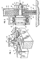
- FIG. 2 is a sectional view taken substantially along line II-II of Figure 1 and illustrating the mounting of a probe and associated slip-ring structure in association with a grinding wheel;
- FIG. 3 is a sectional view, on an enlarged scale, illustrating details of mounting of the probe in the grinding wheel;
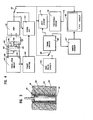
- FIG. 4 is a schematic electrical diagram illustrating circuitry for the apparatus of Figures 1-3, using an eddy current probe of a crossed coil type;
- FIG. 5 is a view illustrating a system for grinding of a part while optically detecting flaws in the surface of the part;
- Reference numeral 10 generally designates a grinding and testing apparatus constructed in accordance with the principles of this invention, shown in use in grinding and simultaneously testing a steel billet 11. The illustrated apparatus includes a
grinding wheel 12 shown with its periphery in engagement with the upper surface of the billet 11. The grindingwheel 12 carries an eddy current probe which moves in proximity tothe surface of the billet 11 during each revolution of thewheel 12. The probe is connected through aslip ring unit 13 and a cable 14 to aninstrument 15 which includes a cathoderay tube display 16 and suitable controls. It will be understood that coupling devices other than a slip ring unit may be used including, for example, an electromagnetic rotary coupling device. - The apparatus 10 is usable, for example, in removing portions of the billet 11 where marks have previously been applied to indicate the location of surface and subsurface cracks or other defects. The operator, using a
control handle 18 and acontrol button 19 energizes anelectric motor 20 to rotate thewheel 12 and then moves thewheel 12 into engagement with the billet 11, in a position as illustrated, while looking for a crack indication on thedisplay 16 and/or listening for an audible crack indication which may also be produced by theinstrument 15. - When a crack indication is observed or heard, the operator may continue grinding, stopping when the crack indication disappears. Then billet-handling apparatus (not shown) may be operated to move the billet relative to the grinder and to position another defect-indicating mark opposite the
wheel 12. Such billet-handling apparatus may desirably include means for moving the billet 11 longitudinally and may also function to rotate the billet about its axis. - With the apparatus 10, a crack or defect may be indicated with a high degree of accuracy and reliability and only the defective portion of the billet is removed. Each grinding operation can be quickly performed so that the operator may move on to the next marked region of the billet 11.
- The defect-indicating marks may be applied, for example, through a magnetic particle inspection procedure in which finely divided magnetic particles, usually in a liquid carrier, are applied over the surface of the billet 11 to be concentrated over any surface and subsurface cracks or defects which create leakage fields. The part may be magnetized during the application of the particles or may be magnetized prior to the application thereof, to leave a residual field. The marks may be provided by the concentrations of magnetic particles and may be augmented by applying paint or the like thus clearly indicating the position of a defective region of the part.
- The grinding
wheel 12 may be supported and driven by any suitable arrangement and, in some applications, it may be desirable to rotate the grindingwheel 12 about a stationary axis while moving the part to a position in which it is engaged by thewheel 12. In the illustrated arrangement, thegrinding wheel 12 is supported on ashaft 22 which is journalled bybearings housing 25. Apulley 26 on theshaft 22 is coupled through abelt 27 to a pulley (not shown) on the shaft of themotor 20. Themotor 20 serves as a counter-balance and is secured to thehousing 25 and to anarm 28 which are pivotal on ahorizontal shaft 30.Shaft 30 extends between the lower ends of a pair of rigidly connectedarms horizontal shaft 33 carried by afixed support 34. With this type of arrangement, the operator may move thegrinding wheel 12 vertically as well as horizontally, in a direction transverse to the longitudinal axis of the billet 11, to position thewheel 12, as desired. Relative movement in a longitudinal direction may be controlled by moving the billet 11. It will be understood that the invention is not limited to any particular support and drive arrangement for the billet and, although specific features of the invention relate to the mounting of a testing probe in a grinding wheel, the invention can be applied to other types of surface treating operations including operations in which a surface treating member is not rotatable. - The
grinding wheel 12 is mounted on theshaft 22 between a pair offlanges nut 37 threaded on the end of theshaft 22, with awasher 38 being disposed between thenut 37 and theflange 36. The slip ring unit 13-includes arotatable part 39 threaded or otherwise secured on the end of theshaft 22 and astationary part 40 which is connected to the end of the cable 14 and which is connected to abracket 41 on an end plate 42 of ashroud 43 for thegrinding wheel 12. Electrical contacts within therotatable part 39 of theslip ring unit 13 are connected through acable 45 to an eddycurrent probe 46 which is mounted in the outer end of a radially extendingpassage 47 formed in thegrinding wheel 12. - An important specific feature relates to the mounting of the
probe 46 in a manner such as to adjust for wear of the periphery of thegrinding wheel 12 during operation. In the illustrated arrangement, theprobe 46 is initially positioned with its terminal end in flush alignment with the outer peripheral surface of thegrinding wheel 12 but means are provided to permit movement radially inwardly when the periphery of thegrinding wheel 12 wears, so as to maintain the terminal end of theprobe 46 in flush alignment with the outer peripheral surface of thewheel 12. As illustrated in Figure 3,bristles 48 are secured to theprobe 46 and extend radially away from the axis of theprobe 46 as well as radially outwardly with respect to the axis of thegrinding wheel 12. Thebristles 48 engageserrations 49 formed on the inner surface of asleeve 50 which is disposed within thepassage 47.Sleeve 50 preferably has a thin wall and is of a material such as brass or aluminum which will readily wear away as the periphery of thegrinding wheel 12 wears away. Thebristles 48 allow the probe to be moved radially inwardly but engage theserrations 49 to prevent outward movement of theprobe 46 in response to centrifugal force. - The provision of the
sleeve 50 is highly advantageous in most applications but in others it may not be necessary and thebristles 48 may directly engage the inside surface of thepassage 47 which, being formed in a grinding wheel, is inherently a rough surface providing a high degree of friction. It is also possible to form thesleeve 50 by coating the inside surface of thepassage 47 with a suitable hardenable plastic material, such as an epoxy, and then forming, if necessary, serrations or grooves therein. It should also be understood that the probe may be actively retracted by providing a servomechanism. Other types of probes may be used. For example, theprobe 46 may be supported on an arm attached to the side of thewheel 12. - As shown in the enlarged detail view of Figure 3, the
bristles 48 may preferably be secured to asleeve 51 on the outside of theprobe 46 and athin wear member 52 may be secured to the outer terminal end of theprobe 46 for protecting the probe during operation. Theprobe 46, by way of example, may be an eddy current probe of a crossed coil type, with a construction and operation as disclosed in U.S. Patent No. 3,495,166. However, other types of eddy current probes may be used, including probes using only one coil, and it is also possible to use other types of magnetic probes, particularly probes of the type operative to detect leakage fields. - Figure 4 is a schematic diagram illustrating a circuit usable with a probe of the crossed coil type. A pair of
coils probe 46 are connected in series and tooutput terminals oscillator 57 which may include an output driver stage with an output transformer having a secondary winding connected to theterminals balance potentiometers terminals potentiometer 59 being connected to the junction between thecoils potentiometer 60 is connected to one input of anamplifier 61 having a second input terminal connected to ground. - The output of the
amplifier 61 is connectable through aselector switch 62 to indicating circuitry and is also connected to one input of aphase detector 63 which has a second input connected to the output of aphase shifter 64 which is connected to the oscillator circuit. In a second position of theselector switch 62, the output of thephase detector 63 is connected to the indicating circuitry. - In the illustrated arrangement, the indicating circuitry includes a cathode
ray tube circuit 66 which has a vertical input connected to theselector switch 62. A horizontal input of thecircuit 66 is connected to the output of asweep circuit 67 which receives a signal from a timing circuit 68. The timing circuit 68 has an input connectable through aselector switch contact 69 to theselector switch 62, permitting synchronization of the timing circuit with signals detected by the probe. - Alternatively, the input of the timing circuit 68 is connected through the
selector switch contact 69 to a synchronizingpulse circuit 70 which may, for example, respond to a signal pulse developed at a certain angular position of thegrinding wheel 12, during each rotation thereof. The output of the probe circuitry, at theselector switch 62, may also be connected through agate circuit 71 and athreshold circuit 72 to an indicating circuit 73-which may, for example, energize an audible signal device. Thegate circuit 71 is connected to the timing circuit 68 and may be so controlled as to be operative only during movement of theprobe 46 past the engaged portion of the billet 11. Thethreshold circuit 72 may be adjusted to develop an output signal only when the detected signal is above a certain amplitude. - Non-destructive testing probes other than electromagnetic probes may be used to detect flaws in the surface of a part being ground or otherwise subjected to a surface treating operation.
- Figure 5 illustrates a system for optical detection of flaws, generally designated by
reference numeral 75 in thesystem 75, a plasticfiber light guide 76 is disposed in apassage 77 in agrinding wheel 78 with a terminal end of theguide 76 being flush with the peripheral surface of thegrinding wheel 78, to move into proximity to asurface 79 of apart 80 during each rotation of thewheel 78. Thelight guide 76 extends through a slot 81 in ashaft 82 on which thegrinding wheel 78 is mounted and an opposite terminal end of theguide 76 projects through a centeringdisk 84 which is held on the end of theshaft 82 by aholder 85 threaded on the end of theshaft 82. Anut 86 is threaded on theshaft 82 to hold thewheel 78 betweenflanges nut 86 andflange 88. A fitting 90 may be diposed in theslot 86 to hold thelight guide 76 in place, the fitting 90 and the slot 81 having spaced facing arcuate surfaces together defining a passage for receiving theguide 76. - A
laser 92 is positioned to project a beam along the axis of rotation of thegrinding wheel 78 and through a beam splitter 93 and alens 94 to impinge on the terminal end of theguide 76 which is on the axis of thegrinding wheel 78. The light from thelaser 92 is transmitted through theguide 76 to thesurface 79 to be reflected therefrom and back through thelight guide 76 and through thelens 96 to impinge on a reflective surface of the beam splitter 93. The light reflected from the beam splitter 93 is received by aphotomultiplier 95 which includes a fitting 96 defining an entrance window through which light may be received and measured. Anoptical bandpass filter 97 is secured to the fitting 96. - The beam splitter 93 functions to allow transmission of light from the
laser 92 to the end of thelight guide 76 and to transmit reflected light to thephotomultiplier 95, while blocking transmission of light directly from the laser and from the beam splitter 93 to thephotomultiplier 95. The beam splitter may be of a conventional type or may be in the form of a mirror having a very small central aperture through which the laser beam is projected, it being noted that the reflected light is dispersed through a substantial angle of divergence. - The
lens 94 serves to focus the laser beam on the end of thelight guide 76 but more importantly, it serves to collect the reflected light and to transmit the collected transmitted light to the beam splitter and thence to thephotomultiplier 95. As a result, the arrangement is highly sensitive to variations in the light reflected from thesurface 79. - By way of example and not by way of limitation, the
light guide 76 may be a plastic fiber having a diameter of 0.036 inches. Thelens 94 is a 5X microscope objective with a NA of 0.1, thelens 94 being effective to magnify the reflected light from 0.036 inches at the end of theguide 76 to 0.180 inches at the window of thephotomultiplier 95. It is possible to provide a lens between the beam splitter 93 and thephotomultiplier 95, rather than between the beam splitter 93 and the light guide end but the arrangement as shown has the advantage that it is more efficient in transmitting a wide cone at the light guide end into a narrow cone at the photomultiplier window. - The
filter 97 serves to improve the signal to noise ratio, especially with respect to limiting interference from room lights. By way of example, a filter may be used having a center wavelength of 6328 Angstroms and a band width of on the order of 80 to 160 Angstroms. - The output of the
photomultiplier 95 is applied through anamplifier 98, a low pass filter 99, agate circuit 100 and athreshold circuit 101 to anoutput circuit 102. Thegate circuit 100 is controlled from atiming circuit 103 which is connected to areed switch 104 adjacent the path of movement of amagnet 105 carried by thesupport flange 88 for thegrinding wheel 78. Thetiming circuit 103 may also control theoutput circuit 102 which may include a CRT or other visible display device. - Although not shown in Figure 5, it will be understood that means are provided for supporting the optical components in accurate relationship to the axis of rotation of the
grinding wheel 78. All of the optical components as well as the bearings for thesupport shaft 82 should be securely mounted on a common support. In some applications, it may be desirable to mount all of such components on a stationary support and move the part to be treated into cooperative relationship to thegrinding wheel 78 or other surface treating member. - The system of Figure 5 is capable of detecting relatively narrow grooves or other defects in the surface of a part. It has a potential disadvantage in connection with a billet-grinding operation in which relatively coarse particles of a grinding wheel may become positioned opposite the end of the
light guide 76 to block transmission of light. In other grinding operations or for polishing or other surface-treating operations, it may be used to advantage. - It will be understood that modifications and variations may be effected without departing from the spirit and scope of the novel concepts of this invention.
Claims (25)
Priority Applications (1)
| Application Number | Priority Date | Filing Date | Title |
|---|---|---|---|
| AT83107676T ATE38436T1 (en) | 1982-08-12 | 1983-08-04 | DEVICE FOR TREATMENT AND STUDY OF A SURFACE. |
Applications Claiming Priority (2)
| Application Number | Priority Date | Filing Date | Title |
|---|---|---|---|
| US407656 | 1982-08-12 | ||
| US06/407,656 US4502253A (en) | 1982-08-12 | 1982-08-12 | Surface treating and testing apparatus |
Publications (3)
| Publication Number | Publication Date |
|---|---|
| EP0103141A2 true EP0103141A2 (en) | 1984-03-21 |
| EP0103141A3 EP0103141A3 (en) | 1984-09-12 |
| EP0103141B1 EP0103141B1 (en) | 1988-11-02 |
Family
ID=23612982
Family Applications (1)
| Application Number | Title | Priority Date | Filing Date |
|---|---|---|---|
| EP83107676A Expired EP0103141B1 (en) | 1982-08-12 | 1983-08-04 | Surface treating and testing apparatus |
Country Status (6)
| Country | Link |
|---|---|
| US (1) | US4502253A (en) |
| EP (1) | EP0103141B1 (en) |
| JP (1) | JPS5985905A (en) |
| AT (1) | ATE38436T1 (en) |
| CA (1) | CA1198297A (en) |
| DE (1) | DE3378378D1 (en) |
Cited By (4)
| Publication number | Priority date | Publication date | Assignee | Title |
|---|---|---|---|---|
| GB2173300A (en) * | 1985-04-06 | 1986-10-08 | Schaudt Maschinenbau Gmbh | Apparatus for optically monitoring the surface finish of ground workpieces |
| GB2502989A (en) * | 2012-06-12 | 2013-12-18 | Sperry Rail International Ltd | Investigating the propagation of a crack in a rail |
| DE102018211761A1 (en) * | 2018-07-16 | 2020-01-16 | MTU Aero Engines AG | Device with an examination means for the non-destructive examination of a component and method for examining a component |
| CN111136555A (en) * | 2020-01-03 | 2020-05-12 | 广东韶钢松山股份有限公司 | Peeling method for rolled square billet |
Families Citing this family (7)
| Publication number | Priority date | Publication date | Assignee | Title |
|---|---|---|---|---|
| JPS63237867A (en) * | 1987-03-23 | 1988-10-04 | Daisho Seiki Kk | Grinding wheel position detector for surface grinding machine |
| FR2750632B1 (en) * | 1996-07-08 | 1998-10-30 | Efsa | METHOD AND DEVICE FOR GRINDING A THICKNESS OF A METAL PART |
| CN1926666A (en) * | 2004-03-11 | 2007-03-07 | 东洋橡胶工业株式会社 | Polishing pad and method of manufacturing semiconductor device |
| DE102004027846B4 (en) * | 2004-06-08 | 2007-06-06 | Fraunhofer-Gesellschaft zur Förderung der angewandten Forschung e.V. | Grinding device with integrated micromagnetic sensors |
| DE102008021569A1 (en) * | 2008-04-30 | 2009-11-05 | Advanced Micro Devices, Inc., Sunnyvale | System and method for optical endpoint detection during CMP using a substrate spanning signal |
| CN101900665B (en) * | 2009-05-25 | 2012-06-13 | 中国钢铁股份有限公司 | Estimation method of abrasion wheel grinding parameter |
| US8833187B2 (en) * | 2011-02-23 | 2014-09-16 | Ut-Battelle, Llc | Stack sampling apparatus |
Citations (3)
| Publication number | Priority date | Publication date | Assignee | Title |
|---|---|---|---|---|
| US3495166A (en) * | 1967-04-10 | 1970-02-10 | Magnaflux Corp | Eddy current crack detector systems using crossed coils |
| US4027982A (en) * | 1975-04-23 | 1977-06-07 | Kyodo Denshi Kogyo Co., Ltd. | Needle detector for circular knitting machines |
| FR2465564A1 (en) * | 1979-09-18 | 1981-03-27 | Inoue Japax Res | GRINDING FOR GRINDING MACHINE AND METHOD FOR CONTROLLING THE SAME |
Family Cites Families (8)
| Publication number | Priority date | Publication date | Assignee | Title |
|---|---|---|---|---|
| US2947121A (en) * | 1959-03-25 | 1960-08-02 | Norton Co | Grinding wheel and wheel diameter measuring apparatus |
| JPS4910480A (en) * | 1972-05-30 | 1974-01-29 | ||
| DE2422940B2 (en) * | 1974-05-11 | 1976-06-10 | Werkzeugmaschinenfabrik Adolf Waldrich Coburg, 8630 Coburg | DEVICE FOR CONTROLLING THE INFEED MOVEMENT OF A ROTATING TOOL CARRIED BY A TOOL SPINDLE, IN PARTICULAR A GRINDING WHEEL |
| SU509416A1 (en) * | 1974-12-31 | 1976-04-05 | Всесоюзный Заочный Машиностроительныйинститут | A device for measuring the temperature zone grinding |
| US3953943A (en) * | 1975-02-27 | 1976-05-04 | Shimadzu Seisakusho Ltd. | Apparatus for automatically detecting and eliminating flaws on slabs or billets |
| DE2523375A1 (en) * | 1975-05-27 | 1976-12-09 | Jun German Gresser | DEVICE FOR FULLY AUTOMATIC, PART-DEPENDENT, ELECTRONIC LIGHT-IMPULSE (L-I) CONTROL OF GRINDING OR POLISHING AND CUTTING MACHINES OF ALL KINDS |
| US4199902A (en) * | 1978-07-17 | 1980-04-29 | Sauerland Franz L | Apparatus for automatic lapping control |
| DE2953191A1 (en) * | 1979-05-25 | 1982-02-04 | Sumitomo Metal Ind | SURFACE DEFECT DETECTOR FOR STEEL MEMBER |
-
1982
- 1982-08-12 US US06/407,656 patent/US4502253A/en not_active Expired - Fee Related
-
1983
- 1983-08-04 AT AT83107676T patent/ATE38436T1/en not_active IP Right Cessation
- 1983-08-04 EP EP83107676A patent/EP0103141B1/en not_active Expired
- 1983-08-04 DE DE8383107676T patent/DE3378378D1/en not_active Expired
- 1983-08-09 CA CA000434168A patent/CA1198297A/en not_active Expired
- 1983-08-12 JP JP58146811A patent/JPS5985905A/en active Pending
Patent Citations (3)
| Publication number | Priority date | Publication date | Assignee | Title |
|---|---|---|---|---|
| US3495166A (en) * | 1967-04-10 | 1970-02-10 | Magnaflux Corp | Eddy current crack detector systems using crossed coils |
| US4027982A (en) * | 1975-04-23 | 1977-06-07 | Kyodo Denshi Kogyo Co., Ltd. | Needle detector for circular knitting machines |
| FR2465564A1 (en) * | 1979-09-18 | 1981-03-27 | Inoue Japax Res | GRINDING FOR GRINDING MACHINE AND METHOD FOR CONTROLLING THE SAME |
Cited By (6)
| Publication number | Priority date | Publication date | Assignee | Title |
|---|---|---|---|---|
| GB2173300A (en) * | 1985-04-06 | 1986-10-08 | Schaudt Maschinenbau Gmbh | Apparatus for optically monitoring the surface finish of ground workpieces |
| GB2173300B (en) * | 1985-04-06 | 1989-06-28 | Schaudt Maschinenbau Gmbh | Apparatus for optically monitoring the surface finish of ground workpieces |
| GB2502989A (en) * | 2012-06-12 | 2013-12-18 | Sperry Rail International Ltd | Investigating the propagation of a crack in a rail |
| DE102018211761A1 (en) * | 2018-07-16 | 2020-01-16 | MTU Aero Engines AG | Device with an examination means for the non-destructive examination of a component and method for examining a component |
| CN111136555A (en) * | 2020-01-03 | 2020-05-12 | 广东韶钢松山股份有限公司 | Peeling method for rolled square billet |
| CN111136555B (en) * | 2020-01-03 | 2023-10-20 | 广东韶钢松山股份有限公司 | Rolling square billet peeling method |
Also Published As
| Publication number | Publication date |
|---|---|
| US4502253A (en) | 1985-03-05 |
| JPS5985905A (en) | 1984-05-18 |
| CA1198297A (en) | 1985-12-24 |
| EP0103141B1 (en) | 1988-11-02 |
| ATE38436T1 (en) | 1988-11-15 |
| EP0103141A3 (en) | 1984-09-12 |
| DE3378378D1 (en) | 1988-12-08 |
Similar Documents
| Publication | Publication Date | Title |
|---|---|---|
| US4502253A (en) | Surface treating and testing apparatus | |
| US3761186A (en) | Apparatus for optically inspecting the condition of a surface having known variations in the condition | |
| IL40443A (en) | Method and apparatus for determining the properties of jewellery stones | |
| US4417147A (en) | Method and apparatus for measuring runout in a cylindrical object | |
| US5031360A (en) | Broken blade detector for semiconductor die saws | |
| JPS5965708A (en) | Sonde for automatic surface inspection | |
| US7046351B2 (en) | Method and apparatus for measuring eccentricity of optical lens, and method and apparatus for centering and edging optical lens | |
| US5719840A (en) | Optical sensor with an elliptical illumination spot | |
| US4430614A (en) | Eddy current bearing ball flaw detector | |
| US3873830A (en) | Method and apparatus for monitoring the quality of welds in seamed tubes | |
| US11047675B2 (en) | Method and apparatus for inspection of spherical surfaces | |
| US6067857A (en) | Braking element processing system | |
| JPH01212352A (en) | Method and apparatus for electromagnetic flaw detection | |
| JPS5933855B2 (en) | Surface inspection method | |
| JPS60104633A (en) | Method and device for determining position of drill | |
| US3099743A (en) | Combined electron probe microanalyzer and x-ray diffraction instrument | |
| JPS62235511A (en) | Surface condition inspecting apparatus | |
| KR100194347B1 (en) | Friction Coefficient Measuring Device for Rotating Shaft for Shaft Perturbation Actuator | |
| JPH1114328A (en) | Rotational accuracy measuring device of rotating body | |
| JPS61194335A (en) | Scanning type surface film analyzing method and apparatus | |
| JPH03276049A (en) | Optical head for optical surface inspecting machine | |
| JPH01502535A (en) | Optical inspection system for cylindrical objects | |
| JPS60146148A (en) | Eddy flaw detector | |
| KR830002286Y1 (en) | Device for detecting defects in metal plate by eddy current | |
| SU1335806A1 (en) | Device for centring light conductors at installation thereof in working machine |
Legal Events
| Date | Code | Title | Description |
|---|---|---|---|
| PUAI | Public reference made under article 153(3) epc to a published international application that has entered the european phase |
Free format text: ORIGINAL CODE: 0009012 |
|
| AK | Designated contracting states |
Designated state(s): AT BE CH DE FR GB IT LI LU NL SE |
|
| PUAL | Search report despatched |
Free format text: ORIGINAL CODE: 0009013 |
|
| AK | Designated contracting states |
Designated state(s): AT BE CH DE FR GB IT LI LU NL SE |
|
| 17P | Request for examination filed |
Effective date: 19850309 |
|
| 17Q | First examination report despatched |
Effective date: 19860428 |
|
| D17Q | First examination report despatched (deleted) | ||
| GRAA | (expected) grant |
Free format text: ORIGINAL CODE: 0009210 |
|
| AK | Designated contracting states |
Kind code of ref document: B1 Designated state(s): AT BE CH DE FR GB IT LI LU NL SE |
|
| REF | Corresponds to: |
Ref document number: 38436 Country of ref document: AT Date of ref document: 19881115 Kind code of ref document: T |
|
| ITF | It: translation for a ep patent filed |
Owner name: JACOBACCI & PERANI S.P.A. |
|
| REF | Corresponds to: |
Ref document number: 3378378 Country of ref document: DE Date of ref document: 19881208 |
|
| ET | Fr: translation filed | ||
| PG25 | Lapsed in a contracting state [announced via postgrant information from national office to epo] |
Ref country code: GB Effective date: 19890804 Ref country code: AT Effective date: 19890804 |
|
| PG25 | Lapsed in a contracting state [announced via postgrant information from national office to epo] |
Ref country code: SE Effective date: 19890805 |
|
| PLBE | No opposition filed within time limit |
Free format text: ORIGINAL CODE: 0009261 |
|
| STAA | Information on the status of an ep patent application or granted ep patent |
Free format text: STATUS: NO OPPOSITION FILED WITHIN TIME LIMIT |
|
| PGFP | Annual fee paid to national office [announced via postgrant information from national office to epo] |
Ref country code: FR Payment date: 19890830 Year of fee payment: 7 |
|
| PG25 | Lapsed in a contracting state [announced via postgrant information from national office to epo] |
Ref country code: LU Free format text: LAPSE BECAUSE OF NON-PAYMENT OF DUE FEES Effective date: 19890831 Ref country code: LI Effective date: 19890831 Ref country code: CH Effective date: 19890831 Ref country code: BE Effective date: 19890831 |
|
| 26N | No opposition filed | ||
| BERE | Be: lapsed |
Owner name: MAGNAFLUX CORP. Effective date: 19890831 |
|
| PG25 | Lapsed in a contracting state [announced via postgrant information from national office to epo] |
Ref country code: NL Effective date: 19900301 |
|
| GBPC | Gb: european patent ceased through non-payment of renewal fee | ||
| NLV4 | Nl: lapsed or anulled due to non-payment of the annual fee | ||
| REG | Reference to a national code |
Ref country code: CH Ref legal event code: PL |
|
| PG25 | Lapsed in a contracting state [announced via postgrant information from national office to epo] |
Ref country code: DE Effective date: 19900501 |
|
| PG25 | Lapsed in a contracting state [announced via postgrant information from national office to epo] |
Ref country code: FR Effective date: 19910430 |
|
| REG | Reference to a national code |
Ref country code: FR Ref legal event code: ST |
|
| EUG | Se: european patent has lapsed |
Ref document number: 83107676.5 Effective date: 19900418 |