EP0102877A2 - Nach vorne abnehmbarer Kupplungsring für einen elektrischen Verbinder - Google Patents
Nach vorne abnehmbarer Kupplungsring für einen elektrischen Verbinder Download PDFInfo
- Publication number
- EP0102877A2 EP0102877A2 EP83401556A EP83401556A EP0102877A2 EP 0102877 A2 EP0102877 A2 EP 0102877A2 EP 83401556 A EP83401556 A EP 83401556A EP 83401556 A EP83401556 A EP 83401556A EP 0102877 A2 EP0102877 A2 EP 0102877A2
- Authority
- EP
- European Patent Office
- Prior art keywords
- housing
- electrical connector
- coupling ring
- recited
- annular
- Prior art date
- Legal status (The legal status is an assumption and is not a legal conclusion. Google has not performed a legal analysis and makes no representation as to the accuracy of the status listed.)
- Withdrawn
Links
Images

Classifications
-
- F—MECHANICAL ENGINEERING; LIGHTING; HEATING; WEAPONS; BLASTING
- F16—ENGINEERING ELEMENTS AND UNITS; GENERAL MEASURES FOR PRODUCING AND MAINTAINING EFFECTIVE FUNCTIONING OF MACHINES OR INSTALLATIONS; THERMAL INSULATION IN GENERAL
- F16L—PIPES; JOINTS OR FITTINGS FOR PIPES; SUPPORTS FOR PIPES, CABLES OR PROTECTIVE TUBING; MEANS FOR THERMAL INSULATION IN GENERAL
- F16L19/00—Joints in which sealing surfaces are pressed together by means of a member, e.g. a swivel nut, screwed on, or into, one of the joint parts
- F16L19/02—Pipe ends provided with collars or flanges, integral with the pipe or not, pressed together by a screwed member
-
- H—ELECTRICITY
- H01—ELECTRIC ELEMENTS
- H01R—ELECTRICALLY-CONDUCTIVE CONNECTIONS; STRUCTURAL ASSOCIATIONS OF A PLURALITY OF MUTUALLY-INSULATED ELECTRICAL CONNECTING ELEMENTS; COUPLING DEVICES; CURRENT COLLECTORS
- H01R13/00—Details of coupling devices of the kinds covered by groups H01R12/70 or H01R24/00 - H01R33/00
- H01R13/62—Means for facilitating engagement or disengagement of coupling parts or for holding them in engagement
- H01R13/625—Casing or ring with bayonet engagement
Definitions
- This invention relates to an electrical connector and more particularly to a coupling ring for the connector.
- An electrical connector assembly is generally comprised of two separate housings connected together by a coupling member mounted on one of the housings.
- a coupling member mounted on one of the housings.
- bayonet type couplings which include an internal groove that mates with a pin on a housing
- threaded couplings which include threads that mate with threads on a housing so that when the coupling member is rotated the housings are drawn together mating the contacts within the housing.
- Both types of coupling members are generally mounted behind an annular flange on one of the housings and held in place by a snap ring. Because of this arrangement when a problem arises with a coupling ring and it must be removed and replaced it is necessary to remove the wires and attached contacts within the connector assembly to remove the coupling ring.
- This invention is an electrical connector that has a forwardly removable coupling ring.
- the coupling ring is characterized by two annular members that are connected ) together by one or more removable fasteners and held in place in front of the annular flange on the connector housing by a snap ring that is snapped into a groove in front of the housing.
- One of the coupling ring members includes a lever to facilitate rotation of the coupling ring.
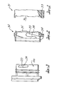
- FIGURE 1 illustrates a portion of a first annular member 31 that forms a portion of the coupling ring.
- the first annular member 31 has a plurality of detents 36 and a passage 33 adapted to receive a fastener for connecting together the first member 31 and second member 32 shown in FIGURE 2.
- FIGURE 2 illustrates the second annular member 32 of the coupling ring.
- the second annular member'32 includes an annular groove 39 extending a predetermined distance on the inside thereof and adapted to receive a projection on another connector housing; a plurality of axial projections 35 adapted to mate with the detents 36 in the first member 31 shown in FIGURE 1 to prevent relative movement between the first and second members when they are connected together; and a passage 34 adapted to receive a removably mounted fastener that connects the first and second members together.
- the forward surface of the groove 39 includes a shoulder 38.
- FIGURE 3 illustrates an electrical connector housing 100 adapted to mate with the second member 32 of the coupling ring.
- the housing includes an elongated projection 139 that mates with the groove 39 in the second member 32 of the coupling ring.
- the elongated projection 139 includes a shoulder 138 adapted-to abut against the shoulder 38 shown in the groove 39 of the second member 32 in FIGURE 2.
- FIGURE 4 shows the projection 139 after it has traveled through the groove 39 from the lower end up to the top portion where the shoulders 138, 38 abut against each other, holding the coupling ring 30 on the housing 100.
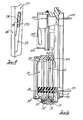
- FIGURE 5 illustrates how the coupling ring incorporating the principles of this invention is mounted forwardly of the annular shoulder 11 of a connector housing 10.
- the first annular member 31 is connected to the second annular member 32 by a nut 51 and a bolt 50, which is located through the passages 33, 34 in the first and second members 31 and 32.
- To assemble the coupling ring 30 on the housing 10 the first member 31 is located I against 'the annular shoulder 11 of the housing 10.
- a snap ring 40 is then placed in groove 12 to retain the first member 33 between the snap ring 40 and the shoulder 11.
- the second annular member 32 is then placed against the first member 31 and bolt 50 is placed through the passages 33, 34 in the first and second members 31, 32 and into nut 51.
- the bolt 50 is tightened the first and second members 31, 32 are removably retained together.
- FIGURE 6 shows an electrical connector assembly incorporating the principles of this invention.
- a housing 10 having the coupling nut 30 mounted thereon is mounted below a housing 100 adapted to receive a coupling nut.
- Both housings 10 and 100 include a plurality of electrical contacts 20, 120 that are mounted within the connector housings 10, 100 and attached to wires 25, 125.
- FIGURE 7 illustrates a front view of the connector assembly shown in FIGURE 6.
- the first member 31 of the coupling ring 30 includes a lever 3 which is used to rotate the coupling ring.
- Projection 60 on the other housing 100 and projection 37 limits the movement of the lever 3 and prepositions the lever 3 for the initial mating with a complementary connector assembly.
Landscapes
- Engineering & Computer Science (AREA)
- General Engineering & Computer Science (AREA)
- Mechanical Engineering (AREA)
- Details Of Connecting Devices For Male And Female Coupling (AREA)
Applications Claiming Priority (2)
| Application Number | Priority Date | Filing Date | Title |
|---|---|---|---|
| US402527 | 1982-07-28 | ||
| US06/402,527 US4468078A (en) | 1982-07-28 | 1982-07-28 | Forwardly removable coupling ring for an electrical connector |
Publications (1)
| Publication Number | Publication Date |
|---|---|
| EP0102877A2 true EP0102877A2 (de) | 1984-03-14 |
Family
ID=23592280
Family Applications (1)
| Application Number | Title | Priority Date | Filing Date |
|---|---|---|---|
| EP83401556A Withdrawn EP0102877A2 (de) | 1982-07-28 | 1983-07-28 | Nach vorne abnehmbarer Kupplungsring für einen elektrischen Verbinder |
Country Status (4)
| Country | Link |
|---|---|
| US (1) | US4468078A (de) |
| EP (1) | EP0102877A2 (de) |
| JP (1) | JPS5946780A (de) |
| CA (1) | CA1197910A (de) |
Cited By (1)
| Publication number | Priority date | Publication date | Assignee | Title |
|---|---|---|---|---|
| US8545497B2 (en) | 2004-03-25 | 2013-10-01 | University College Cork—National University of Ireland, Cork | Apparatus for use in the prophylaxis or treatment of tissue |
Families Citing this family (8)
| Publication number | Priority date | Publication date | Assignee | Title |
|---|---|---|---|---|
| DE8424654U1 (de) * | 1984-08-20 | 1985-12-19 | Allied Corp., Morristown, N.J. | Steckverbinder, insbesondere Rundsteckverbinder |
| FR2594823B1 (fr) * | 1986-02-24 | 1992-06-12 | Ruggieri | Dispositif de liaison entre une meche de mise a feu d'un produit pyrotechnique et un inflammateur |
| US4895530A (en) * | 1989-02-24 | 1990-01-23 | Molex Incorporated | Quick disconnect automotive battery connector |
| US5215476A (en) * | 1991-06-21 | 1993-06-01 | Mac Panel Company | Interface connector assembly |
| JP3184598B2 (ja) * | 1992-04-14 | 2001-07-09 | 株式会社東芝 | 内視鏡コネクタおよび内視鏡装置 |
| US5372517A (en) * | 1993-05-27 | 1994-12-13 | Levesque; Paulo | Cable connector adapter |
| US6450353B1 (en) | 1999-09-27 | 2002-09-17 | The Lamson & Sessions Co. | Floor box cover assembly |
| US6713711B2 (en) | 2001-11-09 | 2004-03-30 | Thermal Dynamics Corporation | Plasma arc torch quick disconnect |
Family Cites Families (12)
| Publication number | Priority date | Publication date | Assignee | Title |
|---|---|---|---|---|
| FR1079927A (fr) * | 1952-04-03 | 1954-12-03 | Fond Emanuele Paterno | Perfectionnements aux raccords étanches pour la connexion d'éléments tubulaires |
| US3221292A (en) * | 1961-10-18 | 1965-11-30 | Bendix Corp | Electrical connector |
| US3271726A (en) * | 1961-11-02 | 1966-09-06 | Bendix Corp | Electrical connector |
| US3328743A (en) * | 1964-06-22 | 1967-06-27 | Northrop Corp | Quick disconnect-electrical |
| US3316524A (en) * | 1965-03-19 | 1967-04-25 | Westinghouse Electric Corp | Cable connector assemblage |
| US3745511A (en) * | 1971-06-16 | 1973-07-10 | Mark Products | Multiconductor cable connector |
| US3711815A (en) * | 1971-06-24 | 1973-01-16 | Gen Connector | Tight angle multi-contact electrical connector |
| US3786396A (en) * | 1972-04-28 | 1974-01-15 | Bunker Ramo | Electrical connector with locking device |
| US3840839A (en) * | 1973-02-01 | 1974-10-08 | Akzona Inc | Asymmetrical electrical connector with aligning means |
| US4185856A (en) * | 1973-04-13 | 1980-01-29 | Mcevoy Oilfield Equipment Company | Pipe joint with remotely operable latch |
| US4390222A (en) * | 1979-10-01 | 1983-06-28 | Automation Industries, Inc. | Lanyard release/umbilical electrical connector |
| US4415213A (en) * | 1981-11-02 | 1983-11-15 | The Bendix Corporation | Hermaphrodite electrical connector |
-
1982
- 1982-07-28 US US06/402,527 patent/US4468078A/en not_active Expired - Fee Related
-
1983
- 1983-05-02 CA CA000427167A patent/CA1197910A/en not_active Expired
- 1983-07-27 JP JP58136019A patent/JPS5946780A/ja active Pending
- 1983-07-28 EP EP83401556A patent/EP0102877A2/de not_active Withdrawn
Cited By (1)
| Publication number | Priority date | Publication date | Assignee | Title |
|---|---|---|---|---|
| US8545497B2 (en) | 2004-03-25 | 2013-10-01 | University College Cork—National University of Ireland, Cork | Apparatus for use in the prophylaxis or treatment of tissue |
Also Published As
| Publication number | Publication date |
|---|---|
| US4468078A (en) | 1984-08-28 |
| CA1197910A (en) | 1985-12-10 |
| JPS5946780A (ja) | 1984-03-16 |
Similar Documents
| Publication | Publication Date | Title |
|---|---|---|
| EP0052530B1 (de) | Kupplungsring eines elektrischen Verbinders mit angeformter Feder | |
| US4389081A (en) | Electrical connector coupling ring | |
| US4059324A (en) | Electrical connector | |
| US4464001A (en) | Coupling nut having an anti-decoupling device | |
| US4359255A (en) | Coupling ring having detent means | |
| US4361374A (en) | Electrical connector bayonet coupling pin | |
| US3808580A (en) | Self-locking coupling nut for electrical connectors | |
| US3663926A (en) | Separable electrical connector | |
| US4443052A (en) | Means to indicate fully-mated condition of electrical connector | |
| US5564942A (en) | Connector for an electrical signal transmitting cable | |
| EP0616387B1 (de) | Steckverbinder | |
| EP0638965B1 (de) | Runde Durchführungsverbinderanordnung | |
| US5593320A (en) | Waterproof connector | |
| US6196865B1 (en) | Removable rear connector for a circular electrical plug | |
| US4497530A (en) | Electrical connector having a coupling indicator | |
| US4519661A (en) | Connector assembly having an anti-decoupling mechanism | |
| US4863396A (en) | Strain relief clamp assembly | |
| CA1153437A (en) | Electrical connector coupling member | |
| EP0102877A2 (de) | Nach vorne abnehmbarer Kupplungsring für einen elektrischen Verbinder | |
| US4448470A (en) | Coupling member and an electrical connector | |
| US4386816A (en) | Electrical connector insert assembly | |
| US4483579A (en) | Electrical connector having improved coupling ring | |
| CA1105584A (en) | Electrical connector | |
| US4548458A (en) | Electrical connector having a molded anti-decoupling mechanism | |
| US4645282A (en) | Releasing electrical connector assembly |
Legal Events
| Date | Code | Title | Description |
|---|---|---|---|
| PUAI | Public reference made under article 153(3) epc to a published international application that has entered the european phase |
Free format text: ORIGINAL CODE: 0009012 |
|
| AK | Designated contracting states |
Designated state(s): DE FR GB IT |
|
| STAA | Information on the status of an ep patent application or granted ep patent |
Free format text: STATUS: THE APPLICATION IS DEEMED TO BE WITHDRAWN |
|
| 18D | Application deemed to be withdrawn |
Effective date: 19860203 |
|
| RIN1 | Information on inventor provided before grant (corrected) |
Inventor name: FREAR, DAVID LEIGH Inventor name: PUNAKO, STEPHEN Inventor name: GALLUSSER, DAVID OTIS Inventor name: MACAVOY, DAVID WARREN |