EP0102870B1 - Portable personal dust collector - Google Patents
Portable personal dust collector Download PDFInfo
- Publication number
- EP0102870B1 EP0102870B1 EP83401538A EP83401538A EP0102870B1 EP 0102870 B1 EP0102870 B1 EP 0102870B1 EP 83401538 A EP83401538 A EP 83401538A EP 83401538 A EP83401538 A EP 83401538A EP 0102870 B1 EP0102870 B1 EP 0102870B1
- Authority
- EP
- European Patent Office
- Prior art keywords
- foam
- trap
- cap
- crown
- prefiltration
- Prior art date
- Legal status (The legal status is an assumption and is not a legal conclusion. Google has not performed a legal analysis and makes no representation as to the accuracy of the status listed.)
- Expired
Links
Images
Classifications
-
- G—PHYSICS
- G01—MEASURING; TESTING
- G01N—INVESTIGATING OR ANALYSING MATERIALS BY DETERMINING THEIR CHEMICAL OR PHYSICAL PROPERTIES
- G01N1/00—Sampling; Preparing specimens for investigation
- G01N1/02—Devices for withdrawing samples
- G01N1/22—Devices for withdrawing samples in the gaseous state
- G01N1/2202—Devices for withdrawing samples in the gaseous state involving separation of sample components during sampling
- G01N1/2205—Devices for withdrawing samples in the gaseous state involving separation of sample components during sampling with filters
-
- G—PHYSICS
- G01—MEASURING; TESTING
- G01N—INVESTIGATING OR ANALYSING MATERIALS BY DETERMINING THEIR CHEMICAL OR PHYSICAL PROPERTIES
- G01N1/00—Sampling; Preparing specimens for investigation
- G01N1/02—Devices for withdrawing samples
- G01N1/22—Devices for withdrawing samples in the gaseous state
- G01N1/24—Suction devices
-
- G—PHYSICS
- G01—MEASURING; TESTING
- G01N—INVESTIGATING OR ANALYSING MATERIALS BY DETERMINING THEIR CHEMICAL OR PHYSICAL PROPERTIES
- G01N1/00—Sampling; Preparing specimens for investigation
- G01N1/02—Devices for withdrawing samples
- G01N1/22—Devices for withdrawing samples in the gaseous state
- G01N1/2202—Devices for withdrawing samples in the gaseous state involving separation of sample components during sampling
- G01N2001/222—Other features
- G01N2001/2223—Other features aerosol sampling devices
Definitions
- the subject of the invention is an individual sensor, which any person can carry with him, serving to take suspended dust from the surrounding atmosphere and to retain for purposes of subsequent analysis those which have dimensions such that they can enter and be retained in this person's alveoli. In this way, one can evaluate and even measure the quantity of so-called breathable dust that a person was likely to inhale during a given period in the various places of an environment where he breathed during this period.
- Dust sampling devices are already known in a polluted atmosphere in which a rotor made of filter material is used which is rotated at a constant speed. The description is found in French Patent No. 2,039,560 and its certificate of addition 2082180.
- French patent no. 2389119 also discloses a device for the selective sampling of dust in a dusty atmosphere.
- French patent no. 2389119 relates to a device which it is said could be adapted to become portable.
- the invention aims to achieve an individual sensor significantly simplified in its constitution in comparison with the device of this patent, having an efficiency at least equal and sufficiently lightened and simplified to be able to be easily produced in the form of a device of small dimensions.
- the invention aims to arrive at a dust collection device as effective as known devices but capable of being worn permanently by a person even during the execution of strenuous or dangerous work.
- the device must therefore be light and compact.
- the means provided on conventional devices for classifying the dusts (cyclone for example) before their capture are no longer acceptable.
- the invention relates to an individual portable dust collector capable of being retained in the lungs, comprising a rotationally driven cup having a bottom and a side wall, a filter foam crown with central channel housed in the cup, an inlet cover. of central air and with lateral air outlet surrounding the cup, an air passage cap covering the central air inlet of the cover and having an extreme end wall, the largest dust separation means housed in said hat.
- said dust separation means consist of at least one prefiltration block filling the cap and there is provided after this (s) block (s) a duct with a straight section decreasing in value for its connection to the central air inlet of the cover, this inlet leading to an outlet orifice of diameter smaller than the central channel of the filter foam crown, arranged coaxially with this channel, this foam crown having a thickness equal to the height of the side wall of the cup and having in a transverse plane a substantially uncovered side face turned towards the side of the central air inlet.
- the aim sought is achieved by the use of different means and by an appropriate different design of the gas stream circuit inside a portable sensor.
- the outlet opening of the conduit has a smaller dimension than that of the central channel of the foam crown. It is preferably located in a transverse plane which is the plane of the exposed lateral face of the foam crown.
- the side air outlet cover has air outlet holes located on two diametrically opposite sides distributed in two opposite angular sectors; preferably these sectors each have a development of approximately 80 °.
- holes are advantageously in a transverse plane which is set back towards the bottom of the cup with respect to the transverse plane of the exposed lateral face of the foam crown; the withdrawal distance is 45 to 50% of the thickness of the foam crown, for example.
- the air passage cap is pierced with at least one hole through its end face, directly in front of the prefiltration block in the direction of air flow through the latter.
- the cap contains a single pre-filtration block of grade 45 filter foam and the crown is of grade 80 or 100 filter foam.
- the cap contains a concave deflector, the concave bottom is located in front of at least one central hole drilled in the end face of the cap and the periphery of which has several spaced openings opening in front of the prefiltration block.
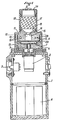
- An individual portable sensor produced in accordance with the invention comprises a hollow body 1 which contains a motor 2 associated with a side switch 3.
- This body 1 is designed to also contain a source of electrical energy under the motor 2.
- the shaft 5 of the motor 2 is vertical, directed upwards through a bearing 6, and it ends in a magnetic plate 7.
- a cup 8 which has a bottom 8A and a side wall 8B.
- This cup 8 contains in its entire volume a ring 9 of filtering foam which has a central channel 10.
- the height of the side wall 8B, or the depth of the cup 8, is identical to the thickness of the foam ring 9 so that the latter has, when it is housed in the cup 8, a fully exposed lateral face 11 situated in a transverse plane 12, indicated in phantom, which is also the plane of the annular end face of the lateral wall 8B.
- the face 11 is turned on the side of the arrival of the air to be filtered but it is not encountered by the air which arrives as will be understood better below.
- the rotary assembly which has just been described is enclosed in a cover 13 fixed to the body 1 in a removable manner.
- This cover 13 has a central air inlet 14 the diameter of which is less than the diameter of the central channel 10 of the foam crown 9.
- this central air inlet 14 leads to an outlet orifice 15 of the same diameter, coaxial with the central channel 10, and which advantageously lies in the transverse plane 12.
- the cover 13 also has an air outlet which is composed of two slots or two rows of holes 16 drilled through the side wall in two places diametrically opposite one on the left and the other on the right in Figure 1. Each row of holes extends over a sector of approximately 80 °. All the holes 16 are in a transverse plane which is set back with respect to the transverse plane 12. The value of this shrinkage is close to half the thickness of the foam crown 9.
- a cap 17 with an air passage covering the central air inlet 14.
- This cap 17 contains at least one block 18 of pre-filtration filter foam which has a diameter greater than that of the inlet d 'central air 14. Between the two is provided a duct 19, for example converging, which communicates with the central channel 14 by connecting with it. In fact, in this example the entire junction zone is made in the cover 13 in which the duct 19 and the central channel 14 are successively formed, terminated by its orifice 15.
- the cap 17 On the other side of the block 18 in filter foam the cap 17 has a transverse end wall 20 through which are pierced several longitudinal air inlet holes 21. These holes 21 open directly opposite the block 18 in the direction of the passage of air through the latter.
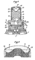
- the cap 17 ends in a transverse end wall 20 ′ having a longitudinal central hole 21 ′ opening opposite the concave bottom of an interior concave deflector 22
- the latter is arranged upstream of the block 18 and it has in its peripheral zone several spaced openings 23 open opposite this block 18, the air sucked in by the rotation of the cup 8 arriving, as indicated by arrows in a current axial center to radially follow the deflector and form several peripheral axial currents directed directly on the prefiltration block 18.
- the pre-filtration block 18 is made of grade 45 open-pore foam (meaning that it has 45 cells per linear inch or 45 cells per 25.4 mm length), while that the crown 9 is of open-pore foam of grade 80 (or 100) or 80 (or 100) cells by length of 25.4 mm.
- the senor described performs a filtration cut-off in the vicinity of a particle size of 5 microns, the largest are retained in the prefiltration block 18, those which are likely to be retained in the lungs (in the range from 5 microns to 0.5 microns) are retained in the foam crown 9; the finest emerge from the sensor through the holes 16.
- FIG. 2 which is a section through a plane substantially similar to the section plane of FIG. 1, the sensor can be worn on the chest, hanging from a user's neck or shoulder.
- the filtration cut-off can be modified, for example to meet existing standards.
- a cut which corresponds to a size of 5 microns of the particles it can be fixed at a different value such as 7 or 10 ⁇ m, for example.
- the variant of the cap 17 illustrated in FIG. 2 is useful in an atmosphere which contains larger particles or fairly large particles in large quantities: they are retained largely in the bottom of the concave deflector 22. It is also possible to place in the deflector 22 a block of filter foam retaining only the largest particles.
- prefiltration block 18 by several successive prefilters of decreasing porosity (that is to say of increasing grade) in order to separate and collect several distinct slices of decreasing particle size and at the same time carry out a summary analysis of the dust dimensions.
- the size of the particles stopped does not only depend on the porosity (or grade) of the foam but also on the speed of the gas passing through it (a higher speed accompanied by the stopping of smaller grains) it is also possible to act on the diameter of the prefilters, for example by surrounding them with a more or less thick solid ring inside the cap 17, in order to produce various prefiltration slices above the dimensions of 5 microns.
- the speed of the gases was 0.35 m / s with an engine running at 7000 rpm and sucking air at a flow rate of 600 1 / h approximately.
- the prefilter had a diameter of 25 mm, a thickness of 20 mm and the crown 9 had an outside diameter of 35 mm.
- FIG. 3 shows in diametral section a crown 9 of grade 80 filter foam, the uncovered side face 11 being seen slightly from above in perspective.
- the air stream charged with dust at 5 microns and less which leaves the orifice 15 is distributed substantially over the entire height of the crown 9 and the crown 8; it is driven out radially by centrifugal force, leaving its dust greater than 0.5 ⁇ m and it leaves via the exposed face 11 using a narrow annular strip 24 along the side wall 8B of the cup 8, bypassing a half central torus 25 cut by the lateral face 11.
- This annular band 24 must always remain uncovered on the face 11.
- This central half-torus 25 depends on the component between on the one hand, the axial speed of the air current at the outlet of the orifice 15 after its concentration by the conduit 19, on the other hand, the speed of rotation of the cup 8 and of the ring 9 made of filter foam.
Landscapes
- Health & Medical Sciences (AREA)
- Life Sciences & Earth Sciences (AREA)
- Biochemistry (AREA)
- General Health & Medical Sciences (AREA)
- Molecular Biology (AREA)
- Physics & Mathematics (AREA)
- Chemical & Material Sciences (AREA)
- Analytical Chemistry (AREA)
- Engineering & Computer Science (AREA)
- Biomedical Technology (AREA)
- General Physics & Mathematics (AREA)
- Immunology (AREA)
- Pathology (AREA)
- Sampling And Sample Adjustment (AREA)
- Filtering Of Dispersed Particles In Gases (AREA)
- Respiratory Apparatuses And Protective Means (AREA)
- Orthopedics, Nursing, And Contraception (AREA)
- Cleaning Implements For Floors, Carpets, Furniture, Walls, And The Like (AREA)
Abstract
Description
L'invention a pour objet un capteur individuel, que toute personne peut porter sur elle, servant à prélever dans l'atmosphère environnante les poussières en suspension et à retenir à des fins d'analyse ultérieure celles qui ont des dimensions telles qu'elles peuvent pénétrer dans les alvéoles pulmonaires de cette personne et y être retenues. De cette façon, on peut évaluer et même doser la quantité de poussières dites respirables qu'une personne a été susceptible d'inhaler pendant une période donnée aux divers endroits d'un milieu où elle a respiré pendant cette période.The subject of the invention is an individual sensor, which any person can carry with him, serving to take suspended dust from the surrounding atmosphere and to retain for purposes of subsequent analysis those which have dimensions such that they can enter and be retained in this person's alveoli. In this way, one can evaluate and even measure the quantity of so-called breathable dust that a person was likely to inhale during a given period in the various places of an environment where he breathed during this period.
On connaît déjà des appareils de prélèvement de poussières dans une atmosphère polluée dans lesquels on se sert d'un rotor en matière filtrante entraîné en rotation à une vitesse constante. On en trouve la description dans le brevet français no 2 039 560 et son certificat d'addition 2082180.Dust sampling devices are already known in a polluted atmosphere in which a rotor made of filter material is used which is rotated at a constant speed. The description is found in French Patent No. 2,039,560 and its certificate of addition 2082180.
On connaît aussi par le brevet français no 2389119 un dispositif de prélèvement sélectif de poussières dans une atmosphère poussiéreuse.French patent no. 2389119 also discloses a device for the selective sampling of dust in a dusty atmosphere.
II s'agit d'appareils conçus pour être portables, c'est-à-dire assez légers pour être déplaçables par une personne seule entre deux points d'utilisation mais trop lourds pour être portés en permanence par cette personne au cours de ces occupations. Typiquement, le poids d'un tel appareil est de l'ordre de 29,4 N (3 kg). Par conséquent, quand on s'en sert on le pose sur le sol ou on le suspend à un endroit nécessairement éloigné des points précis et changeants où cette personne respire pendant ses occupations.These are devices designed to be portable, that is to say light enough to be able to be moved by a single person between two points of use but too heavy to be carried permanently by this person during these occupations. . Typically, the weight of such an apparatus is of the order of 29.4 N (3 kg). Consequently, when it is used, it is placed on the ground or hung at a place necessarily far from the precise and changing points where this person breathes during his occupations.
Or, il est utile d'être renseigné aussi exactement que possible sur la quantité de poussières respirables qu'une personne a pu inhaler effectivement pendant une durée donnée. Les appareils connus ne sont pas satisfaisants à cet égard puisqu'on sait que la densité des poussières varie rapidement entre le lieu même où elles sont produites, non loin duquel respire la personne en question, et le lieu plus éloigné et plus abrité où est placé l'appareil de prélèvement des poussières.However, it is useful to be informed as exactly as possible about the quantity of respirable dust that a person could actually inhale during a given period. Known devices are not satisfactory in this respect since we know that the density of dust varies rapidly between the place where they are produced, not far from which the person in question breathes, and the more distant and sheltered place where is placed the dust collection device.
Le brevet français no 2389119 concerne un dispositif dont il est dit qu'il pourrait être adapté pour devenir portatif. L'invention vise à parvenir à un capteur individuel notablement simplifié dans sa constitution en comparaison du dispositif de ce brevet, ayant une efficacité au moins égale et suffisamment allégé et simplifié pour pouvoir être facilement réalisé sous forme d'un appareil de petites dimensions.French patent no. 2389119 relates to a device which it is said could be adapted to become portable. The invention aims to achieve an individual sensor significantly simplified in its constitution in comparison with the device of this patent, having an efficiency at least equal and sufficiently lightened and simplified to be able to be easily produced in the form of a device of small dimensions.
Plus précisément l'invention a pour but d'arriver à un appareil de captation de poussières aussi efficace que les appareils connus mais susceptibles d'être porté en permanence par une personne même pendant l'exécution d'un travail pénible ou dangereux. L'appareil doit donc être léger et peu encombrant. Il en résulte que les moyens prévus sur les appareils classiques pour opérer une classification des poussières (cyclone par exemple) avant leur captation ne sont plus acceptables.More specifically, the invention aims to arrive at a dust collection device as effective as known devices but capable of being worn permanently by a person even during the execution of strenuous or dangerous work. The device must therefore be light and compact. As a result, the means provided on conventional devices for classifying the dusts (cyclone for example) before their capture are no longer acceptable.
L'invention concerne un capteur portatif individuel de poussières susceptibles d'être retenues dans les poumons, comprenant une coupelle entraînée en rotation ayant un fond et une paroi latérale, une couronne en mousse filtrante à canal central logée dans la coupelle, un couvercle à entrée d'air centrale et à sortie d'air latérale entourant la coupelle, un chapeau à passage d'air coiffant l'entrée d'air centrale du couvercle et ayant une paroi extrême terminale, des moyens de séparation des poussières les plus grosses logés dans ledit chapeau. Selon l'invention, lesdits moyens de séparation des poussières sont constitués par au moins un bloc de préfiltration remplissant le chapeau et il est prévu après ce(s) bloc(s) un conduit à section droite diminuant de valeur pour son raccordement à l'entrée d'air centrale du couvercle, cette entrée aboutissant à un orifice de sortie de diamètre inférieur au canal central de la couronne en mousse filtrante, disposé coaxialement à ce canal, cette couronne en mousse ayant une épaisseur égale à la hauteur de la paroi latérale de la coupelle et présentant dans un plan transversal une face latérale substantiellement découverte tournée du côté de l'entrée d'air centrale.The invention relates to an individual portable dust collector capable of being retained in the lungs, comprising a rotationally driven cup having a bottom and a side wall, a filter foam crown with central channel housed in the cup, an inlet cover. of central air and with lateral air outlet surrounding the cup, an air passage cap covering the central air inlet of the cover and having an extreme end wall, the largest dust separation means housed in said hat. According to the invention, said dust separation means consist of at least one prefiltration block filling the cap and there is provided after this (s) block (s) a duct with a straight section decreasing in value for its connection to the central air inlet of the cover, this inlet leading to an outlet orifice of diameter smaller than the central channel of the filter foam crown, arranged coaxially with this channel, this foam crown having a thickness equal to the height of the side wall of the cup and having in a transverse plane a substantially uncovered side face turned towards the side of the central air inlet.
Le but recherché s'atteint par l'emploi de moyens différents et par une conception différente appropriée du circuit du courant gazeux à l'intérieur d'un capteur portatif.The aim sought is achieved by the use of different means and by an appropriate different design of the gas stream circuit inside a portable sensor.
L'orifice de sortie du conduit a une dimension inférieure à celle du canal central de la couronne en mousse. Il se trouve, de préférence, dans un plan transversal qui est le plan de la face latérale découverte de la couronne en mousse.The outlet opening of the conduit has a smaller dimension than that of the central channel of the foam crown. It is preferably located in a transverse plane which is the plane of the exposed lateral face of the foam crown.
Le couvercle à sortie d'air latérale présente des trous de sortie d'air situés sur deux côtés diamétralement opposés répartis dans deux secteurs angulaires opposés; de préférence ces secteurs ont chacun un développement de 80° environ.The side air outlet cover has air outlet holes located on two diametrically opposite sides distributed in two opposite angular sectors; preferably these sectors each have a development of approximately 80 °.
Ces trous se trouvent avantageusement dans un plan transversal qui est en retrait en direction du fond de la coupelle par rapport au plan transversal de la face latérale découverte de la couronne en mousse; la distance de retrait est de 45 à 50% de l'épaisseur de la couronne en mousse, par exemple.These holes are advantageously in a transverse plane which is set back towards the bottom of the cup with respect to the transverse plane of the exposed lateral face of the foam crown; the withdrawal distance is 45 to 50% of the thickness of the foam crown, for example.
De préférence, le chapeau à passage d'air est percé d'au moins un trou à travers sa face extrême, directement en face du bloc de préfiltration dans le sens de circulation d'air à travers ce dernier.Preferably, the air passage cap is pierced with at least one hole through its end face, directly in front of the prefiltration block in the direction of air flow through the latter.
Selon un mode préféré de réalisation de l'invention, le chapeau contient un seul bloc de préfiltration en mousse filtrante de grade 45 et la couronne est en mousse filtrante de grade 80 ou 100.According to a preferred embodiment of the invention, the cap contains a single pre-filtration block of grade 45 filter foam and the crown is of grade 80 or 100 filter foam.
En variante, il est possible de disposer en série à l'intérieur du chapeau plusieurs blocs successifs de préfiltration à plusieurs grades différents intermédiaires de plus en plus fins avant la couronne en mousse. Selon une autre variante, le chapeau contient un déflecteur concave dont le fond concave est situé en face d'au moins un trou central percé dans la face extrême du chapeau et dont la périphérie présente plusieurs ouvertures espacées s'ouvrant en face du bloc de préfiltration.As a variant, it is possible to arrange in series inside the cap several successive pre-filtration blocks with several different grades of increasingly fine intermediates before the foam crown. According to another variant, the cap contains a concave deflector, the concave bottom is located in front of at least one central hole drilled in the end face of the cap and the periphery of which has several spaced openings opening in front of the prefiltration block.
On donnera maintenant, sans intention limitative, une description d'un exemple préféré de réalisation de l'invention. On se reportera au dessin annexé dans lequel:
- - la figure 1 est une vue en coupe par un plan longitudinal d'un capteur individuel portatif conforme à l'invention,
- - la figure 2 est une vue schématique partielle montrant une variante du chapeau de l'appareil de la figure 1,
- - la figure 3 est une vue en coupe diamétrale et en perspective d'une couronne en mousse après utilisation du capteur de la figure 1.
- FIG. 1 is a sectional view through a longitudinal plane of an individual portable sensor according to the invention,
- FIG. 2 is a partial schematic view showing a variant of the cap of the device in FIG. 1,
- FIG. 3 is a view in diametral section and in perspective of a foam crown after use of the sensor of FIG. 1.
Un capteur portatif individuel réalisé conformément à l'invention comprend un corps creux 1 qui contient un moteur 2 associé à un interrupteur latéral 3. Ce corps 1 est conçu pour contenir aussi en dessous du moteur 2 une source d'énergie électrique 4. En position d'utilisation l'arbre 5 du moteur 2 est vertical, dirigé vers le haut à travers un palier 6, et il se termine par un plateau aimanté 7. A ce dernier adhère pour être entraîné en rotation une coupelle 8 qui a un fond 8A et une paroi latérale 8B. Cette coupelle 8 contient dans la totalité de son volume une couronne 9 en mousse filtrante qui a un canal central 10. La hauteur de la paroi latérale 8B, ou la profondeur de la coupelle 8, est identique à l'épaisseur de la couronne en mousse 9 de sorte que celle-ci présente, quand elle est logée dans la coupelle 8, une face latérale 11 totalement découverte située dans un plan transversal 12, indiqué en trait mixte, qui est aussi le plan de la face extrême annulaire de la paroi latérale 8B. La face 11 est tournée du côté de l'arrivée de l'air à filtrer mais elle n'est pas rencontrée par l'air qui arrive comme on le comprendra mieux plus loin.An individual portable sensor produced in accordance with the invention comprises a hollow body 1 which contains a
L'ensemble rotatif qui vient d'être décrit est enfermé dans un couvercle 13 fixé au corps 1 de façon démontable. Ce couvercle 13 a une entrée d'air centrale 14 dont le diamètre est inférieur au diamètre du canal central 10 de la couronne en mousse 9. De plus, cette entrée d'air centrale 14 aboutit à une orifice de sortie 15 de même diamètre, coaxial au canal central 10, et qui se trouve avantageusement dans le plan transversal 12. Le couvercle 13 a également une sortie d'air qui est composée de deux fentes ou de deux rangées de trous 16 percés à travers la paroi latérale en deux endroits diamétralement opposés l'un à gauche et l'autre à droite sur la figure 1. Chaque rangée de trous s'étend sur un secteur de 80° environ. Tous les trous 16 se trouvent dans un plan transversal qui est en retrait par rapport au plan transversal 12. La valeur de ce retrait est voisine de la moitié de l'épaisseur de la couronne en mousse 9.The rotary assembly which has just been described is enclosed in a
Sur le couvercle 13 est monté un chapeau 17 à passage d'air coiffant l'entrée d'air centrale 14. Ce chapeau 17 contient au moins un bloc 18 en mousse filtrante de préfiltration qui a un diamètre supérieur à celui de l'entrée d'air centrale 14. Entre les deux est prévu un conduit 19, convergent par exemple, qui communique avec le canal central 14 en se raccordant avec lui. En fait, dans cet exemple toute la zone de jonction est réalisée dans le couvercle 13 dans lequel sont ménagés successivement le conduit 19 et le canal central 14 terminé par son orifice 15. De l'autre côté du bloc 18 en mousse filtrante le chapeau 17 a une paroi terminale transversale 20 à travers laquelle sont percés plusieurs trous longitudinaux 21 d'entrée d'air. Ces trous 21 s'ouvrent directement en face du bloc 18 dans le sens du passage de l'air à travers ce dernier.On the
Dans une variante du capteur portatif de l'invention illustré par la figure 2, le chapeau 17 se termine par une paroi terminale transversale 20' ayant un trou central longitudinal 21' s'ouvrant en face du fond concave d'un déflecteur concave intérieur 22. Ce dernier est disposé en amont du bloc 18 et il a dans sa zone périphérique plusieurs ouvertures espacées 23 ouvertes en face de ce bloc 18, l'air aspiré par la rotation de la coupelle 8 arrivant, comme indiqué par des flèches en un courant axial central pour suivre radialement le déflecteur et former plusieurs courants axiaux périphériques dirigés directement sur le bloc 18 de préfiltration.In a variant of the portable sensor of the invention illustrated in FIG. 2, the
Quand le capteur portatif individuel est destiné à son usage essentiel, le bloc de préfiltration 18 est en mousse à pores ouverts de grade 45 (signifiant qu'elle a 45 cellules par pouce linéaire ou 45 cellules par longueur de 25,4 mm), tandis que la couronne 9 est en mousse à pores ouverts de grade 80 (ou 100) soit 80 (ou 100) cellules par longueur de 25,4 mm.When the individual portable sensor is intended for its essential use, the
Ainsi constitué, le capteur décrit réalise une coupure de filtration au voisinage d'une grosseur de particules de 5 microns, les plus grosses sont retenues dans le bloc 18 de préfiltration, celles qui sont susceptibles d'être retenues dans les poumons (dans la gamme de 5 microns à 0,5 micron) sont retenues dans la couronne en mousse 9; les plus fines ressortent du capteur par les trous 16. Comme ceux-ci sont placés sur deux côtés opposés, comme le montre aussi la figure 2 qui est une coupe par un plan sensiblement analogue au plan de coupe de la figure 1, le capteur peut être porté sur la poitrine, suspendu au cou ou à l'épaule d'un utilisateur.Thus constituted, the sensor described performs a filtration cut-off in the vicinity of a particle size of 5 microns, the largest are retained in the
En choisissant pour le bloc de préfiltration 18 une mousse de grade différent de celui qui est indiqué plus haut on peut modifier la coupure de filtration, par exemple pour satisfaire à des normes existantes. En particulier, au lieu de choisir une coupure qui correspond à une grosseur de 5 microns des particules on peut la fixer à une valeur différente comme 7 ou 10 pm, par exemple.By choosing a foam of different grade from that indicated above for the
La variante du chapeau 17 illustré par la figure 2 est utile dans une atmosphère qui contient des particules plus grosses ou des particules assez grosses en grande quantité: elles sont retenues en grande partie dans le fond du déflecteur concave 22. On pourrait aussi placer dans le déflecteur 22 un bloc de mousse filtrante ne retenant que les particules les plus grosses.The variant of the
Il est possible de remplacer le bloc de préfiltration 18 par plusieurs préfiltres successifs de porosité décroissante (c'est-à-dire de grade croissant) afin de séparer et de recueillir plusieurs tranches distinctes de granulométrie décroissante et opérer du même coup une analyse sommaire des dimensions des poussières.It is possible to replace the
Etant donné que la dimension des particules arrêtées ne dépend pas que de la porosité (ou du grade) de la mousse mais aussi de la vitesse du gaz qui la traverse (une vitesse plus élevée s'accompagnant de l'arrêt de grains plus petits) on peut agir aussi sur le diamètre des préfiltres, par exemple en les entourant d'une bague pleine plus ou moins épaisse à l'intérieur du chapeau 17, afin de réaliser diverses tranches de préfiltration au-dessus des dimensions de 5 microns.Since the size of the particles stopped does not only depend on the porosity (or grade) of the foam but also on the speed of the gas passing through it (a higher speed accompanied by the stopping of smaller grains) it is also possible to act on the diameter of the prefilters, for example by surrounding them with a more or less thick solid ring inside the
Pour fixer les idées à ce sujet, on précisera que dans le capteur décrit ici en exemple, la vitesse des gaz était de 0,35 m/s avec un moteurtournant à 7000t/mn et aspirant de l'air à un débit de 600 1/h environ. Le préfiltre avait un diamètre de 25 mm, une épaisseur de 20 mm et la couronne 9 avait un diamètre extérieur de 35 mm.To fix ideas on this subject, it will be specified that in the sensor described here as an example, the speed of the gases was 0.35 m / s with an engine running at 7000 rpm and sucking air at a flow rate of 600 1 / h approximately. The prefilter had a diameter of 25 mm, a thickness of 20 mm and the
La figure 3 montre en coupe diamétrale une couronne 9 en mousse filtrante de grade 80, la face latérale 11 découverte étant vue légèrement de dessus en perspective. Le courant d'air chargé de poussières à 5 microns et moins qui sort de l'orifice 15 est réparti sensiblement sur toute la hauteur de la couronne 9 et de la couronne 8; il est chassé radialement par la force centrifuge en abandonnant ses poussières supérieures à 0,5 u.m et il sort par la face découverte 11 en empruntant une bande annulaire étroite 24 le long de la paroi latérale 8B de la coupelle 8, en contournant un demi-tore central 25 coupé par la face latérale 11. Cette bande annulaire 24 doit toujours rester découverte sur la face 11. Le profil de ce demi-tore central 25 dépend de la composante entre d'une part, la vitesse axiale du courant d'air à la sortie de l'orifice 15 après sa concentration par le conduit 19, d'autre part, la vitesse de rotation de la coupelle 8 et de la couronne 9 en mousse filtrante.FIG. 3 shows in diametral section a
Une pesée précise avant et après utilisation de la coupelle 8 contenant la couronne 9 en mousse ou de celle-ci seule fournit le poids des poussières retenues par l'appareil.Precise weighing before and after use of the cup 8 containing the
Claims (10)
Priority Applications (1)
| Application Number | Priority Date | Filing Date | Title |
|---|---|---|---|
| AT83401538T ATE23225T1 (en) | 1982-08-03 | 1983-07-26 | PORTABLE CUSTOM DUST COLLECTOR. |
Applications Claiming Priority (2)
| Application Number | Priority Date | Filing Date | Title |
|---|---|---|---|
| FR8213541A FR2531534A1 (en) | 1982-08-03 | 1982-08-03 | PORTABLE INDIVIDUAL DUST COLLECTOR |
| FR8213541 | 1982-08-03 |
Publications (2)
| Publication Number | Publication Date |
|---|---|
| EP0102870A1 EP0102870A1 (en) | 1984-03-14 |
| EP0102870B1 true EP0102870B1 (en) | 1986-10-29 |
Family
ID=9276583
Family Applications (1)
| Application Number | Title | Priority Date | Filing Date |
|---|---|---|---|
| EP83401538A Expired EP0102870B1 (en) | 1982-08-03 | 1983-07-26 | Portable personal dust collector |
Country Status (10)
| Country | Link |
|---|---|
| US (1) | US4534230A (en) |
| EP (1) | EP0102870B1 (en) |
| JP (1) | JPS5944638A (en) |
| AT (1) | ATE23225T1 (en) |
| AU (1) | AU567684B2 (en) |
| CA (1) | CA1212340A (en) |
| DE (1) | DE3367279D1 (en) |
| FR (1) | FR2531534A1 (en) |
| PL (1) | PL140399B1 (en) |
| ZA (1) | ZA835573B (en) |
Cited By (1)
| Publication number | Priority date | Publication date | Assignee | Title |
|---|---|---|---|---|
| DE102006002653B4 (en) * | 2005-01-27 | 2009-10-08 | Luderer Schweißtechnik GmbH | Dry Ice Blasting |
Families Citing this family (16)
| Publication number | Priority date | Publication date | Assignee | Title |
|---|---|---|---|---|
| FR2585832B1 (en) * | 1985-08-05 | 1987-10-16 | Charbonnages De France | IMPROVED PORTABLE INDIVIDUAL SENSOR FOR DUST ANALYSIS |
| JPS63191943A (en) * | 1987-02-04 | 1988-08-09 | Toshiba Eng & Constr Co Ltd | Transportable dust sampler |
| FR2705783B1 (en) * | 1993-05-28 | 1995-08-25 | Lorraine Laminage | Device for collecting dust in a gas stream. |
| US5511409A (en) * | 1994-09-19 | 1996-04-30 | Knaebel; Kent S. | Measurement of emission levels in a gas stream |
| US6099609A (en) * | 1998-07-30 | 2000-08-08 | 3M Innovative Properties Company | Moving sorbent filter device |
| US6277176B1 (en) | 1998-07-30 | 2001-08-21 | 3M Innovative Properties Company | Moving filter device having filter elements with flow passages and method of filtering air |
| US6099608A (en) * | 1998-07-30 | 2000-08-08 | 3M Innovative Properties Company | Rotating filtration cartridge and blower for HVAC applications |
| US20040237671A1 (en) * | 2003-05-28 | 2004-12-02 | Zefon International, Inc. | Gas sampling apparatus |
| DE102012004838A1 (en) * | 2012-03-13 | 2013-09-19 | Wöhler Meßgeräte Kehrgeräte GmbH | filter cartridge |
| CN112629963A (en) * | 2015-03-06 | 2021-04-09 | 艾法史密斯公司 | Method and container for preparing analysis fusion sample |
| CN105181396B (en) * | 2015-09-11 | 2018-05-15 | 北京市化工职业病防治院 | A kind of personal breathing dust sampling device |
| USD916248S1 (en) | 2018-02-16 | 2021-04-13 | Zefon International, Inc. | Filter cassette |
| EP3752019A4 (en) * | 2018-02-16 | 2021-11-17 | Zefon International, Inc. | Improved device for collecting particulate matter |
| TWI667463B (en) * | 2018-03-21 | 2019-08-01 | 巨研科技股份有限公司 | Quick extraction kit |
| CN111841168A (en) * | 2020-07-27 | 2020-10-30 | 王远南 | Environment-friendly flue gas treatment device |
| CN112304714B (en) * | 2020-10-28 | 2022-12-06 | 中国科学院、水利部成都山地灾害与环境研究所 | Sampling device for tree trunk greenhouse gas |
Family Cites Families (9)
| Publication number | Priority date | Publication date | Assignee | Title |
|---|---|---|---|---|
| DE733715C (en) * | 1941-03-13 | 1943-04-01 | Auergesellschaft Ag | Air conveyor for gas purging devices |
| FR2039560A5 (en) * | 1969-04-04 | 1971-01-15 | Charbonnages De France | |
| FR2040622A5 (en) * | 1969-04-04 | 1971-01-22 | Charbonnages De France | |
| FR2086984A5 (en) * | 1970-04-15 | 1971-12-31 | Charbonnages De France | |
| SU523334A1 (en) * | 1973-07-05 | 1976-07-30 | Предприятие П/Я А-7113 | Apparatus for determining the dispersed composition of aerosols |
| US3949594A (en) * | 1974-09-25 | 1976-04-13 | The United States Of America As Represented By The Secretary Of Interior | Two-stage disposable particle sampling head |
| FR2389119A1 (en) * | 1977-04-25 | 1978-11-24 | Charbonnages De France | SELECTIVE DUST SAMPLING DEVICE ACCORDING TO GRANULOMETRY |
| SU851075A1 (en) * | 1979-10-01 | 1981-07-30 | Липецкое Специализированное Конструк-Topckoe Бюро Всесоюзного Научно- Производственного Объединения"Союзавтоматстром" | Method of controlling clinker firing process |
| SU840704A1 (en) * | 1979-10-11 | 1981-06-23 | Уральский Филиал Всесоюзного Научно-Исследовательского И Конструкторскогоинститута "Цветметавтоматика" | Device for monitoring dust-content of gases |
-
1982
- 1982-08-03 FR FR8213541A patent/FR2531534A1/en active Granted
-
1983
- 1983-07-26 DE DE8383401538T patent/DE3367279D1/en not_active Expired
- 1983-07-26 EP EP83401538A patent/EP0102870B1/en not_active Expired
- 1983-07-26 AT AT83401538T patent/ATE23225T1/en not_active IP Right Cessation
- 1983-07-29 ZA ZA835573A patent/ZA835573B/en unknown
- 1983-08-01 US US06/519,244 patent/US4534230A/en not_active Expired - Fee Related
- 1983-08-01 AU AU17490/83A patent/AU567684B2/en not_active Expired
- 1983-08-02 PL PL1983243277A patent/PL140399B1/en unknown
- 1983-08-02 JP JP58140632A patent/JPS5944638A/en active Granted
- 1983-08-02 CA CA000433697A patent/CA1212340A/en not_active Expired
Cited By (1)
| Publication number | Priority date | Publication date | Assignee | Title |
|---|---|---|---|---|
| DE102006002653B4 (en) * | 2005-01-27 | 2009-10-08 | Luderer Schweißtechnik GmbH | Dry Ice Blasting |
Also Published As
| Publication number | Publication date |
|---|---|
| FR2531534A1 (en) | 1984-02-10 |
| EP0102870A1 (en) | 1984-03-14 |
| AU567684B2 (en) | 1987-12-03 |
| PL243277A1 (en) | 1984-04-24 |
| US4534230A (en) | 1985-08-13 |
| ATE23225T1 (en) | 1986-11-15 |
| AU1749083A (en) | 1984-02-09 |
| CA1212340A (en) | 1986-10-07 |
| FR2531534B1 (en) | 1985-01-11 |
| JPS5944638A (en) | 1984-03-13 |
| DE3367279D1 (en) | 1986-12-04 |
| PL140399B1 (en) | 1987-04-30 |
| JPH0344257B2 (en) | 1991-07-05 |
| ZA835573B (en) | 1984-04-25 |
Similar Documents
| Publication | Publication Date | Title |
|---|---|---|
| EP0102870B1 (en) | Portable personal dust collector | |
| FR2478992A1 (en) | COMPACT ELECTRIC VACUUM CLEANER FOR DRY AND WET MATERIALS | |
| KR100554236B1 (en) | Cyclone dust collector and vacuum cleaner thereof | |
| FR2865917A1 (en) | CYCLONE DUST COLLECTOR | |
| US6131239A (en) | Ground debris vacuum | |
| US20210369067A1 (en) | Vacuum cleaner | |
| JPH0744913B2 (en) | Centrifuge | |
| EP0211761B1 (en) | Portable personal collector for analysing dust | |
| FR2588662A1 (en) | DUST COLLECTOR, ATTACH TO A PERSON'S HABITS. | |
| EP1450662B1 (en) | Waste separating device for vacuum cleaner | |
| CA1112582A (en) | Selective sampling of dust particles according to thickness | |
| FR2586364A1 (en) | INDIVIDUAL SUSPENSION DUST CLASSIFIER | |
| EP0128827A1 (en) | Method and portable carrying-out device for detecting atmospheric contamination by means of alpha particle aerosols | |
| EP0373045B1 (en) | Portable personal sampler for collecting a given fraction of airborne particles | |
| JP7187039B2 (en) | filter device | |
| JPS59152063A (en) | Treatment of grinding and polishing dusts and apparatus thereof | |
| CA2502641C (en) | Distributor for rotary filter and rotary filter equipped therewith | |
| CN116530872A (en) | Dust-gas separation assembly, filtering device and cleaning equipment | |
| FR2469452A1 (en) | Sampling microorganisms in suspension in air - by Petri dish appts. incorporating pipe with diaphragm end opening on to Petri dish and fan for circulating air | |
| EP3152543B1 (en) | Device for picking and transporting nanoobjects contained in aerosols, with a cassette with a module suited to reducing the suction noise during picking | |
| FR2642994A1 (en) | Air-type separator with centrifugal action | |
| FR2476505A1 (en) | Dust removal appts. for cleaning gases - comprising rotating filter basket inside chimney with cyclone action | |
| JPH0424431Y2 (en) | ||
| Fiorina et al. | Aerobiologic particle sampling by a new personal collector (Partrap FA52) in comparison to the Hirst (Burkard) sampler | |
| EP0516608B1 (en) | Centrifugal cylinder with drum for cleaning or filtering air |
Legal Events
| Date | Code | Title | Description |
|---|---|---|---|
| PUAI | Public reference made under article 153(3) epc to a published international application that has entered the european phase |
Free format text: ORIGINAL CODE: 0009012 |
|
| 17P | Request for examination filed |
Effective date: 19830728 |
|
| AK | Designated contracting states |
Designated state(s): AT BE CH DE GB IT LI LU NL SE |
|
| ITF | It: translation for a ep patent filed |
Owner name: BARZANO' E ZANARDO MILANO S.P.A. |
|
| GRAA | (expected) grant |
Free format text: ORIGINAL CODE: 0009210 |
|
| AK | Designated contracting states |
Kind code of ref document: B1 Designated state(s): AT BE CH DE GB IT LI LU NL SE |
|
| REF | Corresponds to: |
Ref document number: 23225 Country of ref document: AT Date of ref document: 19861115 Kind code of ref document: T |
|
| REF | Corresponds to: |
Ref document number: 3367279 Country of ref document: DE Date of ref document: 19861204 |
|
| BECN | Be: change of holder's name |
Effective date: 19861029 |
|
| RAP2 | Party data changed (patent owner data changed or rights of a patent transferred) |
Owner name: CHARBONNAGES DE FRANCE, ETABLISSEMENT PUBLIC DITE: |
|
| PLBE | No opposition filed within time limit |
Free format text: ORIGINAL CODE: 0009261 |
|
| STAA | Information on the status of an ep patent application or granted ep patent |
Free format text: STATUS: NO OPPOSITION FILED WITHIN TIME LIMIT |
|
| RAP2 | Party data changed (patent owner data changed or rights of a patent transferred) |
Owner name: CHARBONNAGES DE FRANCE, ETABLISSEMENT PUBLIC DIT: |
|
| NLT2 | Nl: modifications (of names), taken from the european patent patent bulletin |
Owner name: ETABLISSEMENT PUBLIC DITE: CHARBONNAGES DE FRANCE |
|
| 26N | No opposition filed | ||
| BECN | Be: change of holder's name |
Effective date: 19870812 |
|
| REG | Reference to a national code |
Ref country code: CH Ref legal event code: PFA Free format text: CHARBONNAGES DE FRANCE |
|
| ITTA | It: last paid annual fee | ||
| PGFP | Annual fee paid to national office [announced via postgrant information from national office to epo] |
Ref country code: BE Payment date: 19920702 Year of fee payment: 10 |
|
| PGFP | Annual fee paid to national office [announced via postgrant information from national office to epo] |
Ref country code: GB Payment date: 19920703 Year of fee payment: 10 |
|
| PGFP | Annual fee paid to national office [announced via postgrant information from national office to epo] |
Ref country code: SE Payment date: 19920720 Year of fee payment: 10 |
|
| PGFP | Annual fee paid to national office [announced via postgrant information from national office to epo] |
Ref country code: LU Payment date: 19920722 Year of fee payment: 10 |
|
| PGFP | Annual fee paid to national office [announced via postgrant information from national office to epo] |
Ref country code: AT Payment date: 19920730 Year of fee payment: 10 |
|
| PGFP | Annual fee paid to national office [announced via postgrant information from national office to epo] |
Ref country code: NL Payment date: 19920731 Year of fee payment: 10 |
|
| PGFP | Annual fee paid to national office [announced via postgrant information from national office to epo] |
Ref country code: CH Payment date: 19920805 Year of fee payment: 10 |
|
| PGFP | Annual fee paid to national office [announced via postgrant information from national office to epo] |
Ref country code: DE Payment date: 19920930 Year of fee payment: 10 |
|
| EPTA | Lu: last paid annual fee | ||
| PG25 | Lapsed in a contracting state [announced via postgrant information from national office to epo] |
Ref country code: LU Free format text: LAPSE BECAUSE OF NON-PAYMENT OF DUE FEES Effective date: 19930726 Ref country code: GB Effective date: 19930726 Ref country code: AT Effective date: 19930726 |
|
| PG25 | Lapsed in a contracting state [announced via postgrant information from national office to epo] |
Ref country code: SE Effective date: 19930727 |
|
| PG25 | Lapsed in a contracting state [announced via postgrant information from national office to epo] |
Ref country code: LI Effective date: 19930731 Ref country code: CH Effective date: 19930731 Ref country code: BE Effective date: 19930731 |
|
| BERE | Be: lapsed |
Owner name: CHARBONNAGES DE FRANCE Effective date: 19930731 |
|
| PG25 | Lapsed in a contracting state [announced via postgrant information from national office to epo] |
Ref country code: NL Effective date: 19940201 |
|
| NLV4 | Nl: lapsed or anulled due to non-payment of the annual fee | ||
| GBPC | Gb: european patent ceased through non-payment of renewal fee |
Effective date: 19930726 |
|
| REG | Reference to a national code |
Ref country code: CH Ref legal event code: PL |
|
| PG25 | Lapsed in a contracting state [announced via postgrant information from national office to epo] |
Ref country code: DE Effective date: 19940401 |
|
| EUG | Se: european patent has lapsed |
Ref document number: 83401538.0 Effective date: 19940210 |