EP0102600B1 - Method and apparatus for a magnetic recording/reproducing - Google Patents
Method and apparatus for a magnetic recording/reproducing Download PDFInfo
- Publication number
- EP0102600B1 EP0102600B1 EP83108437A EP83108437A EP0102600B1 EP 0102600 B1 EP0102600 B1 EP 0102600B1 EP 83108437 A EP83108437 A EP 83108437A EP 83108437 A EP83108437 A EP 83108437A EP 0102600 B1 EP0102600 B1 EP 0102600B1
- Authority
- EP
- European Patent Office
- Prior art keywords
- signal
- information
- heads
- pulse
- time
- Prior art date
- Legal status (The legal status is an assumption and is not a legal conclusion. Google has not performed a legal analysis and makes no representation as to the accuracy of the status listed.)
- Expired
Links
Images


Classifications
-
- G—PHYSICS
- G11—INFORMATION STORAGE
- G11B—INFORMATION STORAGE BASED ON RELATIVE MOVEMENT BETWEEN RECORD CARRIER AND TRANSDUCER
- G11B5/00—Recording by magnetisation or demagnetisation of a record carrier; Reproducing by magnetic means; Record carriers therefor
- G11B5/02—Recording, reproducing, or erasing methods; Read, write or erase circuits therefor
- G11B5/09—Digital recording
-
- G—PHYSICS
- G11—INFORMATION STORAGE
- G11B—INFORMATION STORAGE BASED ON RELATIVE MOVEMENT BETWEEN RECORD CARRIER AND TRANSDUCER
- G11B15/00—Driving, starting or stopping record carriers of filamentary or web form; Driving both such record carriers and heads; Guiding such record carriers or containers therefor; Control thereof; Control of operating function
- G11B15/18—Driving; Starting; Stopping; Arrangements for control or regulation thereof
- G11B15/46—Controlling, regulating, or indicating speed
- G11B15/467—Controlling, regulating, or indicating speed in arrangements for recording or reproducing wherein both record carriers and heads are driven
- G11B15/4673—Controlling, regulating, or indicating speed in arrangements for recording or reproducing wherein both record carriers and heads are driven by controlling the speed of the tape while the head is rotating
- G11B15/4675—Controlling, regulating, or indicating speed in arrangements for recording or reproducing wherein both record carriers and heads are driven by controlling the speed of the tape while the head is rotating with provision for information tracking
-
- G—PHYSICS
- G11—INFORMATION STORAGE
- G11B—INFORMATION STORAGE BASED ON RELATIVE MOVEMENT BETWEEN RECORD CARRIER AND TRANSDUCER
- G11B20/00—Signal processing not specific to the method of recording or reproducing; Circuits therefor
- G11B20/00007—Time or data compression or expansion
-
- G—PHYSICS
- G11—INFORMATION STORAGE
- G11B—INFORMATION STORAGE BASED ON RELATIVE MOVEMENT BETWEEN RECORD CARRIER AND TRANSDUCER
- G11B20/00—Signal processing not specific to the method of recording or reproducing; Circuits therefor
- G11B20/10—Digital recording or reproducing
- G11B20/10527—Audio or video recording; Data buffering arrangements
-
- G—PHYSICS
- G11—INFORMATION STORAGE
- G11B—INFORMATION STORAGE BASED ON RELATIVE MOVEMENT BETWEEN RECORD CARRIER AND TRANSDUCER
- G11B27/00—Editing; Indexing; Addressing; Timing or synchronising; Monitoring; Measuring tape travel
- G11B27/02—Editing, e.g. varying the order of information signals recorded on, or reproduced from, record carriers
- G11B27/031—Electronic editing of digitised analogue information signals, e.g. audio or video signals
- G11B27/032—Electronic editing of digitised analogue information signals, e.g. audio or video signals on tapes
-
- G—PHYSICS
- G11—INFORMATION STORAGE
- G11B—INFORMATION STORAGE BASED ON RELATIVE MOVEMENT BETWEEN RECORD CARRIER AND TRANSDUCER
- G11B27/00—Editing; Indexing; Addressing; Timing or synchronising; Monitoring; Measuring tape travel
- G11B27/02—Editing, e.g. varying the order of information signals recorded on, or reproduced from, record carriers
- G11B27/031—Electronic editing of digitised analogue information signals, e.g. audio or video signals
- G11B27/036—Insert-editing
-
- G—PHYSICS
- G11—INFORMATION STORAGE
- G11B—INFORMATION STORAGE BASED ON RELATIVE MOVEMENT BETWEEN RECORD CARRIER AND TRANSDUCER
- G11B5/00—Recording by magnetisation or demagnetisation of a record carrier; Reproducing by magnetic means; Record carriers therefor
- G11B5/008—Recording on, or reproducing or erasing from, magnetic tapes, sheets, e.g. cards, or wires
- G11B5/00813—Recording on, or reproducing or erasing from, magnetic tapes, sheets, e.g. cards, or wires magnetic tapes
- G11B5/00847—Recording on, or reproducing or erasing from, magnetic tapes, sheets, e.g. cards, or wires magnetic tapes on transverse tracks
- G11B5/0086—Recording on, or reproducing or erasing from, magnetic tapes, sheets, e.g. cards, or wires magnetic tapes on transverse tracks using cyclically driven heads providing segmented tracks
-
- H—ELECTRICITY
- H04—ELECTRIC COMMUNICATION TECHNIQUE
- H04N—PICTORIAL COMMUNICATION, e.g. TELEVISION
- H04N5/00—Details of television systems
- H04N5/76—Television signal recording
- H04N5/91—Television signal processing therefor
- H04N5/92—Transformation of the television signal for recording, e.g. modulation, frequency changing; Inverse transformation for playback
- H04N5/928—Transformation of the television signal for recording, e.g. modulation, frequency changing; Inverse transformation for playback the sound signal being pulse code modulated and recorded in time division multiplex with the modulated video signal
-
- H—ELECTRICITY
- H04—ELECTRIC COMMUNICATION TECHNIQUE
- H04N—PICTORIAL COMMUNICATION, e.g. TELEVISION
- H04N9/00—Details of colour television systems
- H04N9/79—Processing of colour television signals in connection with recording
- H04N9/80—Transformation of the television signal for recording, e.g. modulation, frequency changing; Inverse transformation for playback
- H04N9/802—Transformation of the television signal for recording, e.g. modulation, frequency changing; Inverse transformation for playback involving processing of the sound signal
-
- G—PHYSICS
- G11—INFORMATION STORAGE
- G11B—INFORMATION STORAGE BASED ON RELATIVE MOVEMENT BETWEEN RECORD CARRIER AND TRANSDUCER
- G11B2220/00—Record carriers by type
- G11B2220/90—Tape-like record carriers
Definitions
- This invention relates to a helical scan type information recording/ reproducing apparatus, especially to a magnetic tape recording/ reproducing apparatus for recording/reproducing a large amount of information on a magnetic tape.
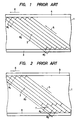
- a helical scan type information recording/ reproducing apparatus Some prior art examples of a helical scan type information recording/ reproducing apparatus are a consumer-use VTR (video tape recorder) represented by the VHS format, a tape pattern of which is shown in Figure 1, and another consumer-use VTR, known as an 8 mm-Video, a tape pattern of which is shown in Figure 2. Examples of such apparatus may be seen from the Taniguichi et al U.S. Patent No. 4,303,950 and the Furumoto et al U.S. Patent No. 4,390,906.
- a video tape 1 is provided with a video track 2 on which a video signal is recorded, a control track 3 on which a control signal is recorded, and an audio track 4 on which an audio signal is recorded.
- the tracing direction of a rotating head is indicated by the arrow 5 and the running direction of the video tape 1 is indicated by the arrow 6.
- the portions ⁇ 1 , 0 2 and 0 3 , respectively, of the video track denote winding angles of the video tape wound around a rotating cylinder.
- the angles ⁇ 1 and 0 3 are nearly equal to 5° and the angle ⁇ 2 is nearly equal to 180°.
- the angle 0 2 corresponds to the duration of recording of the video signal
- the angles ⁇ 1 and 0 3 correspond to the duration of the margin for maintaining an exchangeability of the two rotating heads.
- video may be recorded on the track segment 2, while a track segment 7 is utilized for recording a time-compressed audio signal.
- the numeral 8 designates a first option track
- the numeral 9 designates a second option track.
- the time-compressed audio signal is produced by converting an audio signs to a PCM signal and compressing the PCM signal to about one-sixth time scale.
- the portions ⁇ 1 , ⁇ 2 , ⁇ 3 and 0 4 , respectively, of the video track denote winding angles of the video tape as it is wound around a rotating cylinder.
- the angles ⁇ 1 and 0 3 are nearly equal to 5°.
- the angle 0 2 is nearly equal to 180°
- the angle 0 4 is nearly equal to 30°.
- the angle 0 4 responds to the duration of recording of the time-compressed audio signal.
- each slant track is divided into N segments in the head scanning direction.
- the number N is more than 3. That is, the tape is divided into N information tracks which are disposed in parallel to the direction of the tape running.
- Each of a number of different information items may be independently recorded on each of the N information tracks, or the different information items may be sequentially recorded on the N information tracks along each slant track.
- One of the different information items can be recorded on the information track as voluntarily selected by the operator. Also, the information item can be reproduced from an information track voluntarily selected by the operator.
- the present invention provides a helical scan type magnetic recording/reproducing apparatus including means for selecting one of the N information tracks during the recording mode and the reproducing mode.
- the selecting means comprises a pulse generator for generating a number of track indicating pulses which are phase locked to the rotation of the rotating heads and a data selector connected to the pulse generator for selecting one of the track indicating pulses.
- the selected track indicating pulse is supplied to an information recording/ reproducing processor in order to determine the recording/reproducing timing of the information.
- Figure 3 shows an example of a tape pattern recorded by the present invention, which is applied to the video tape recorder of the 8 mm Video tape.
- each slant track is divided into seven segments 10 - 16 to provide seven information tracks (or channels) A - G. That is, the number N described above is equal to 7.
- the tape pattern of Figure 3 the tape is wound around 220° of the rotating cylinder.
- the information tracks A and G are respectively wound around 35 0 thereof, and the information tracks B. C. D, E and F are respectively wound around 30 thereof.
- Figure 4 shows a specific example of the tape pattern shown in Figure 3; however, in this example. only one time-compressed audio PCM signal is recorded on the information track A selected from the information tracks A - G, and the recorded signal contains a plurality of track segments (A, ... A 7 ).
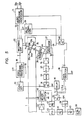
- the apparatus of the present invention shown in Figure 5 is explained hereinafter, with reference to the tape patterns shown in Figures 3 and 4.
- the numerals 22a and 22b denote input terminals from which a 2-channel (stereo) audio signal is applied to an audio signal recording processor 21,
- the audio signal recording processor 21 converts the audio signal into a PCM signal and compresses the audio PCM signal on the time scale.
- the compressed audio PCM signal is supplied to a recording amplifier circuit 20, in which the compressed audio PCM signal is mixed with a pilot signal P from a pilot signal generator 28.
- the output signals Ni or Oi of the recording amplifier circuit 20 are respectively supplied to the rotating heads 23a and 23b of the recording apparatus.
- the recording amplifying circuit 20 will be explained later in detail with reference to Figure 8.
- the rotating heads 23a and 23b are attached to the rotating cylinder 23 which is driven by the cylinder motor 26.
- the numerals 24a and 24b denote two magnets attached to the rotating cylinder 23 at diametrically- opposite points, and the numeral 25 designates a pick-up head.
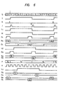
- the pick-up head 25 produces a series of pulses H, as shown in Figure 6.
- the magnet 24a which is positioned a small distance ahead of the rotating head 23a in the rotating direction, produces a series of positive going pulses
- the magnet 24b which is positioned a small distance ahead of the rotating head 23b in the rotating direction, produces a series of negative going pulses.
- the pulses H from the pick-up head 25 are shaped by a pulse generator 27, which may be provided in the form of a delay circuit, a wave-shaping circuit, etc., and produces output pulses I and lo.
- the signal level of the output pulse I is related to the rotating phase or position of the heads 23a and 23b.
- the level of the output pulse I is high, and when the head 23b is tracking on the information track B-G, the level of the output pulse I is low.
- the output pulse I is supplied from the pulse generator 27 to the pilot signal generator 28.
- the pilot signal generator 28 sequentially generates a pilot signal P having frequencies of f 1 , f 2 , f 3 or f 4 in response to the level of the output pulse I.
- the frequency of the pilot signal P Is f 1 or f 3 ; and, on the other hand, when the level of the output pulse I is low, the frequency of the pilot signal P is f 2 or f 4 , as seen in Figure 6, for example.
- the information tracks B-G for each slant track will be modulated at a different pilot frequency, as will be explained hereinafter.
- the pilot signal generator 28 varies the frequencies of the pilot signal P as indicated below.
- the frequencies of the pilot signal P may be selected as follows: (fH : the horizontal synchronous frequency)
- the numeral 30 designates a phase detector that compares the output pulse lo from the pulse generator 27 with an output signal from a monostable multivibrator 33.
- the output pulse lo which is not shown in Figure 6, has the same frequency as the output pulse I, but has a different phase from that of the output pulse I.
- a switch denoted by the numeral 31 is connected to the input terminal of the monostable multivibrator 33. The switch 31 selects either a vertical sync pulse J from a vertical sync pulse separator 32 or a pulse signal M from a delay circuit 35.
- the switch 31 selects the pulse signal M, which is derived from an output pulse of a cyrstal oscillator 39 via dividers 40, 38 and 34.
- the divider 35 In response to the input pulse K, the divider 35 produces parallel output pulses L, - L b , certain ones of which are shown in Figure 6.
- the parallel output pulses L, - L 6 are used for track indicating pulses
- the output pulse L is delayed by the delay circuit 35 and becomes the pulse signal M.
- the turning of the pulse signal M is compared with the output pulse lo in the phase detector 30.
- the monostable multivibrator 33 is provided to convert the vertical sync pulse J, which is 60 Hz, to a frame pulse of 30 Hz. However, the monostable multivibrator 33 has no influence on the pulse signal M, which is already 30 Hz.
- the output signal of the phase detector 30 is amplified by an amplifier 29 and controls the rotating phase of the cylinder motor 26. As a result, the rotation of the rotating heads 23a and 23b is phase locked to the track indicating pulses L: - L 6 .
- the track indicating pulses L, - L 6 are also supplied to a data selector 36, which has an input terminal 37 for receiving a track select signal.
- One of the track indicating pulses L, - L 6 selected by the data selector 36 is supplied to the control terminal of the audio signal recording processor 21 via a switch 48.
- the data selector 36 selects the track indicating pulse L 1 in response to the track select signal applied to terminal 37.
- the numeral 45 denotes a capstan motor.
- a phase detector 43 is used to control the speed of the capstan motor 45.
- One of the input signals to the phase detector 43 comes from the crystal oscillator 39.
- the output pulses of the divider 40 is further divided by a divider 41 and supplied to the phase detector 43.
- a frequency generator 46, which is attached to the capstan motor 45, and a pick-up head 47 form a generator for a pulse signal, which is applied to a divider 42.
- the output pulse of the divider 42 is supplied to a phase detector 43.
- a phase error signal from the phase detector 43 is amplified by a motor driving amplifier 44 and drives the capstan motor 45.
- the terminals (N) of the switches 31 and 48 are used in the apparatus to record the tape pattern shown in Figure 2.
- the switches 31 and 48 are controlled by a manual labor.
- the numeral 18 denotes a video signal recording processor, and the numeral 17 denotes an input terminal which receives the video signal.
- the video signal recording processor 18 converts the chrominance signal of the video signal into a low frequency range signal and the luminance signal into an FM signal.
- the vertical synchronous pulse J is supplied to the monostable multivibrator 33 via the switch 31.
- the monostable multivibrator 33 produces the frame pulse, which is compared with the output pulse lo in the phase detector 30. In this case, the audio is compressed and recorded on the information track A.
- Q designates a time axis.
- the head 23a traces the information tracks A - F, as shown in Figure 3.
- the head 23b begins to trace the information track A.
- Both of the heads 23a and 23b track simultaneously on the tape during at least part of the periods (g), (h) and (i). In the same manner, both of them trace on the tape during at least part of the periods (a), (b) and (c), and (m), (n) and (o).
- the head 23a is tracing on the information track A
- the head 23b traces on the information tracks F and G. This is due to the fact that the tape is wound on the cylinder for more than 180°. as already described.
- pilot signal generator 28 is simple, so that when both of the heads 23a and 23b simultaneously record, the frequency of the pilot signal does not vary.
- the time-compressed audio PCM signal recorded on the track segment A 1 is obtained from the audio signal during periods up to and including the period (a) and is modulated by PCM and compressed in the audio signal recording processor 21.
- the signal recorded on the track segment A 2 corresponds to the audio signal during the periods (b) - (g)
- the signal recorded on the track segment A3 corresponds to the audio signal during the periods (h) - (m).
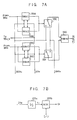
- Figure 7 shows an embodiment of the audio signal recording processor 21 shown in Figure 5.
- the numerals 97a and 97b denote analog compressors
- the numerals 98a and 98b denote analog-digital converters
- the numeral 99 denotes a digital signal processor which operates to perform time compressing, error compensation and other operations on the received digital signals.
- the numerals 100. 101 and 102 respectively denote a phase detector, a voltage controlled oscillator and a divider, which elements form a phase locked loop.
- the numeral 103 denotes a pulse delay circuit using the output pulses from the divider 102 to convert the pulse I or the track indicating pulse Li having the frame frequency into a gate pulse Gi, shown in Figure 6.
- the gate pulse Gi is used in the recording amplifying circuit 20.
- the divider 102 shown in Figure 7 generates several trains of pulses having the the frequencies 2Fh, 16 Fh, 184 Fh, and 368 Fh.
- the A/D converters 98a and 98b shown in Figure 7 receive the pulse having the frequency 16 Fh and convert the analog signals from the analog compressor 97a and 97b to digital signals of 8 bits.
- the digital processor 21 has random access memories (RAMs 1, 2, 3 and 4) 99A - 99D for time-compressing the digital signals at 1/23 compressing rate.
- the RAMs 1 and 3 write the digital signals by using the clock pulse having the frequency 16 Fh
- the RAMs 2 and 4 read the digital signals by using the clock pulse having the frequency 368 Fh.
- the RAMs 1 and 3 read the digital signals by using the clock pulse having the frequency 368 Fh
- the RAMs 2 and 4 write the digital signals by using the clock pulse having the frequency 16 Fh.
- the numerals 99E and 99F designate modulating circuits in which the time compressed digital signals are converted to new digital signals which are easy to record on the magnetic tape, that is.
- the numeral 99G denotes a matrix circuit in which two converted digital signals from the modulating circuits 99E and 99F, and an error compensation signal (an error correction signal), generates the output signal Ai.Bi Ci.
- the pulse delay circuit 103 shown in Figure 7 is made up of a 1/2 divider 103a and a pulse count type monostable multivibrator 103b, as seen in Figure 7B.
- the monostable multivibrator 103b produces an output having the delay time 215/Fh to the pulse I or Li and a pulse width 44/Fh.
- the frequency of the timing pulse K is explained hereinafter.
- the slant track corresponding to 180° of the wound angle is divided into six track segments B - F and a part of segment G, i.e., involve periods (c) through (h).
- the 180° of the wound angle correspond to the pulse width of the output pulse I shown in Figure 6. Accordingly, for the timing pulse K, it is necessary to use a pulse which is phase-locked to the output pulse I and has twelve times the frequency thereof.
- the frequency of the cylinder motor 26 is about 30 Hz. So, in the case where the frequency of the crystal oscillator 39 is 3.58 MHz, to obtain a frequency of 30 Hz,
- the divider 34 divides the timing pulse K to one twelfth, and produces the parallel output pulses Li - L 6 having six different phases; that is, 0 degree, 30 degrees, 60 degrees, 90 degrees, 120 degrees, and 150 degress.
- the data selector 36 selects one of the parallel output pulses L 1 - L 6 as the track indicating pulse, for example, the pulse L 1 in the case where the signal is recorded on the information track A, and the pulse L 2 in case that the signal is recorded on the information track B.
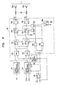
- Figure 8 shows an embodiment of the recording amplifying circuit 20 shown in Figure 5.
- the numeral 149 denotes a mixing circuit for the video signal and the pilot signal and the numeral 150 denotes a mixing circuit for the compressed audio PCM signal and the pilot signal.
- the numerals 151 and 152 designate switches for switching the signals, and the numerals 153 and 154 denote switches for squelching. When the levels of the control signals applied to the switches 151, 152, 153 and 154 are low, the terminals V and N thereof are selected. On the other hand, when they are high, the terminals A and S thereof are selected.
- the numerals 155 and 156 denote driving amplifiers and the numeral 157 designates 2-channel rotary-transformers.
- the numerals 159, 160, 161 and 162 denote AND CIRCUITS.
- the time for recording the compressed audio PCM signal is determined by the signal Gi from the audio recording processor 21, and the signal Gi along with the pulse I, Li (depending on switch 48) control the gates 159 - 162 to operate the switches 151 - 154 to selectively supply the video and compressed audio signals to the heads 23a and 23b with the proper timing.
- Figure 9 shows a tape pattern wherein another audio signal is recorded on the information track B of the tape after another audio signal has been already recorded on the information track A. This may occur when the tape is run in one direction to record the track A, and then is run in the opposite direction to record the track B, for example. On the other hand, after recording the track A by running the tape in the direction 6, for example, the tape may be rewound and run in the direction 6 again to record the track B, or vice versa.
- the data selector 36 shown in Figure 5 selects the track indicating pulse L 2 . Accordingly, the audio signal corresponding to the periods up to and including the period (b) is recorded on the track segment Bi, the audio signal corresponding to the periods (c) - (h) is recorded on the track segment B 2 . and the audio signal corresponding to the periods (i) - (n) is recorded on the track segment B 3 and so forth.
- the pilot signal recorded on the track segment B has the frequency f, or f 3 , and in Figure 6 it is shown as fi. So, the pilot signals of the frequency f 3 , f 4 f 1, f 2, f 3 . , f 4 and f, are respectively recorded on the track segments B,, B 2 , B 3 , B 4 , Bs, B 6 and 8 7 .
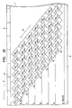
- Figure 10 shows another specific example of the tape pattern shown in Figure 3.
- seven time-compressed audio PCM signals Ti - T 7 are respectively recorded on the information tracks A - G. All segments T 11 , T 12, T 13 ... of the time-compressed audio PCM signal T 1 is recorded on the information track A. Seven segments on each slanting track, for example, T 11, T 21, T 31, T41, Ts1, T 61 and T 71, are recorded in sequence. Accordingly, the same pilot signal f 2 is recorded on the seven segments T 21 , T 31, T 41, Tsi, T 61 , T 71 and T 12 .
- the numeral 117 denotes the tracking pulse recorded on the second option track 9, which tracking pulse is used for the tracking servo similarly to the pilot signal. The reason for this is that one type of reproducing apparatus can only reproduce the tracking pulse for the tracking servo and another type of reproducing apparatus can only reproduce the pilot signal.
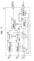
- FIG 11 is a block diagram of an essential part of the apparatus for recording the tape pattern shown in Figure 10.
- the block diagram corresponds to the audio processor 21 and the recording amplifying circuit 20 shown in Figure 5.
- the numerals 121 a and 121 b to 127a and 127b denote the input terminals for seven stereo audio signals.
- the numerals 131 - 137 designate audio processors producing the time-compressed audio PCM signals.
- the numeral 144 denotes a switch-group which has a control terminal 143.
- a control pulse supplied to the control terminal 143 is generated by a flip-flop 142, having an input terminal 141 for receiving a pulse, for example, the gate pulse G 1 shown in Figure 6.
- the numerals 145, 146 and 147 denote mixers.
- the control pulse generated from the flip-flop 142 has the same form as the pulse Li shown in Figure 6.
- the audio processors 131 - 137 are each provided with an information track selecting signal Li which provides for a time separation of the output signals Ti - T 7, i.e., each of the time-compressed audio PCM signals T 1 - T 7 is produced in a respective one of the tracks A - G.
- the signals T 2 - T 6 can be applied through the mixer 145 to the respective mixers 146 and 147 without interference.
- the switch group 144 changes the state X or Y at the rate of 60 Hz.
- the mixers 146 and 147 mix the time-compressed audio PCM signals T 1 - T 7 and the pilot signal.
- the output signals of the mixers 146 and 147 are respectively amplified by the recording amplifiers 148 and 138 and are supplied to the heads 23a and 23b.
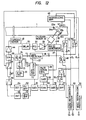
- Figure 12 shows a block diagram of an embodiment of a reproducing apparatus of the present invention.
- the numeral 49 denotes a reproducing amplifying circuit
- the numeral 50 denotes a video signal reproducing processor
- the numeral 51 designates an output terminal for the reproduced video signal
- the numeral 52 denotes an audio signal reproducing processor.
- the audio signal reproducing processor 52 receives a reproduced PCM signal Si and the timing pulses I', Li' and produces 2-channel audio signals to output terminals 53 and 54.
- the numeral 55 denotes a linear amplifier
- the numeral 56 denotes a switch
- the numeral 57 denotes a bandpass filter
- the numerals 58 and 59 denote gate circuits.
- the numeral 60 denotes a converter which produces the product of the output signals of the gate circuits 58 and 59.
- the numerals 61, 62 and 63 respectively denote a gate circuit, a bandpass filter having a central frequency f h and a high Q-factor, and a bandpass filter having a central frequency 3fh and a high Q-factor.
- the numerals 64 and 65 denote amplitude detectors
- the numeral 66 denotes a differential amplifier
- the numeral 67 denotes an inverter
- the numeral 68 denotes a switch.
- the numerals 28, 60, 62, 63, 64, 65, 66, 67 and 68 form a tracking-error detecting circuit for a tracking system having four pilot signals of different frequency.
- the numeral 69 denotes a sample hold circuit.
- the numeral 70 denotes a delay circuit having a delay time longer than the delay circuit 35 shown in Figure 5.
- the numerals 71, 72 and 73 respectively denote an inverter. a switch and a divider having 1 9954 dividing rate.
- the numeral 74 designates a divider having one sixth and one twelfth dividing rates, and which produces the track indicating pulses Li' and the gate pulses Gi'.
- the numerals 75 and 76 respectively denote a data selector and a switch.
- Figure 17 shows the operating position of the switches 48, 72, 76 and 56 for each of the above-listed operating modes.
- the reproduced signals from the heads 23a and 23b are the signals N 1 ', 0,' shown in Figure 13.
- the video signal R, and the compressed audio PCM signal S, are produced from the reproducing amplifying circuit 49.
- the pilot signal P' contained in the video signal R 1 is pulled out by the BPF 57 and is supplied to the tracking servo system.
- the gates 58, 59 and 61, and the sample hold circuit 69 are in the ON-state. It is sufficient that one of the gates 58, 59 and 61.
- the description N/A means that either the terminal N or the terminal A is selected.
- the reproducing signals are the signals N 2' , 0 2 '.
- the output signal from the reproducing amplifying circuit 49 is the compressed audio PCM signal S 2 .
- the gate pulse G 2 ' is applied to the gates 58, 59 and 61, and the sample hold circuit 69.
- the apparatus reproduces the pilot signals f 2 and f 4 recorded by the head 23a, and the pilot signals f i and f 3 recorded by the lead 23b. So the switch 76 selects the terminal A.
- FIG 14 shows a block diagram of the second embodiment of the reproducing apparatus of the present invention.
- the main difference from the apparatus shown In Figure 12 is that a switch denoted by the numeral 77 is provided instead of the switch 76.
- Figure 18 shows the motion of the switches 48, 72, 77 and 56.
- FIG 15 shows a block diagram of the third embodiment of the reproducing apparatus of the present invention.
- the main difference from the apparatus shown in Figure 12 is that an inverter denoted by the numeral 79 and a switch denoted by the numeral 78 are provided instead of the switch 72.
- Figure 19 shows the motion of the switches 48, 78, 77 and 56.
- Figure 16 shows a block diagram of the fourth embodiment of the reproducing apparatus of the present invention.
- the main difference from the apparatus shown in Figure 12 is that the inverter 79 and the switch 78 are provided instead of the switch 76.
- Figure 20 shows the motion of the switches 48, 72, 78 and 56.
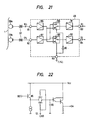
- Figure 21 shows a block diagram of an embodiment of the reproducing amplifying circuit 49 shown in Figure 12.
- the numerals 81 and 82 denote input terminals
- the numeral 83 denotes an output terminal for the compressed audio PCM signal recorded on the information tracks B - G and the video signal
- the numeral 84 denotes an output terminal for the compressed audio PCM signal
- the numeral 85 denotes an input terminal for the pulses I' and Li'
- the numerals 86 and 87 denote head amplifiers
- the numerals 88 and 89 denote switches
- the numeral 90 denotes an inverter
- the numerals 91 and 92 denote buffer amplifiers.
- the gain of the buffer amplifier 91 is about 10 dB larger than that of the buffer amplifier 92.
- any leakage of the compressed audio PCM signal to the video signal becomes a visual interference, but leakage of the video signal to the compressed audio PCM signal produces no problem if the level of the video signal is smaller than a predetermined threshold level. Further, it is desirable to produce as large a chrominance signal or pilot signal as possible. Therefore, the linear amplifier 55, which is provided in the apparatus shown in Figures 12, 14, 15 and 16 to amplify the pilot signal obtained from the signal at the output terminal 34.
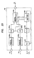
- Figure 22 shows a diagram of an embodiment of the sample and hold circuit 69 used in the apparatus of the present invention.
- the numerals 92, 93, 94 and 95 respectively denote an input terminal, a control terminal receiving the gate pulse Gi', an output terminal and a condenser.
- the signal supplied to the input terminal 92 is straight-forwardly transferred to the output terminal 94.
- the level thereof is low, the voltage indicative of the tracking error is held at the condenser 95.
- All the gates 58, 59 and 61 shows In Figures 12, 14, 15 and 16 transfer the input signal, when the gate pulse G1' is high, and block the input signal, when the gate pulse Gi' is low. There are many positions which the gates 58, 59 and 61 are inserted. However, it is desirable to insert the gates into the input sides of the BPFs 62 and 63 in consideration of the DC offset.
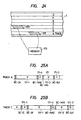
- Figure 23 shows a block diagram of an embodiment of the audio reproducing processor 52 shown in Figure 12.
- the numeral 104 denotes a digital signal processor constructed by a time-expand circuit, an error compensating circuit, etc.
- the numerals 105a and 105b denote a digital-analog converter
- the numerals 106a and 106b denote analog expand circuits which have a reverse characteristic to the analog compressors 97a and 97b.
- the numerals 107, 108 and 109 respectively denote a phase detector, a voltage control oscillator and a divider.
- the digital signal processor 104 performs a function which is the inverse of that performed by the digital signal processor 21, described in detail in conjunction with Figure 7A.
- Figure 24 shows a schematic diagram for explaining the new editing system.
- the numeral 171 denotes a part of the information track A in which a digital signal is recorded.
- the numeral 173 denotes a part of the information track C in which another digital signal is recorded.
- the editing system transfers the digital signal recorded on the part 171 to the part 173 via a memory denoted by the numeral 172.
- a unit of the digital signal is called a word.
- a synchronous signal is inserted every plurality of words in order to know the heading of each word.
- the group of the words with the synchronous signal is called a block.
- a block code for distinguishing the block and other data are recorded on the part in which the synchronous signal is recorded, and which is called a pre-block.
- a post-block is provided as well.
- FIGS. 25A and 25B show schematic diagrams of the information track.
- An initial block code of the part 171 recorded on the information track is BC - IA
- a last block code thereof is BC - EA.
- a small part denoted by the numeral 171-3 is a data block having the block code BC - EA.
- the numerals 171-1, 171-2 and 171-4 denote data blocks.
- the block codes BC - IA and BC - EA are assigned.
- the quantity of data of the part 171 is compared with the capacity of the memory 172.
- the part 171 is divided into the small parts 171-1 and 171-2.
- the block code BC - MAE is the last block code of the small part 171-1 and the block code BC - MAI is the first block code of the small part 171-2. That is, the part 171 is divided into small parts, each of which is capable of being stored in the memory 173, and transferred to the information track C.
- P and R respectively denote the reproducing data and the recording data.
- the data code BC - IC is for the data recorded on the information track C and is indicated in order to record the part 171 on the next part of the information track C. Accordingly, the block code BC - IC, the small part 171-1, the block code BC - MAE and the small part 171-4 are respectively recorded in the positions of the block code BC - IA', the part 171-1', the block code BC - MAE' and the part 171-4' shown in Figure 25B. Similarly, the block code BC - MAIE, the part 171-2, the block BC - EA and the part 171-3 are transferred.
- the tape is properly supplied and taken up.
- This tape carrying operation can be automatically performed by detecting the block codes as well.
- the block codes are generally a series of the sequential numbers. Therefore, each of the block codes recorded after the block code BC - IC on the information track C can be exchanged for the sequential numbers of the block code BC - IC.
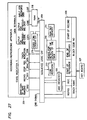
- Figure 26 shows a flow chart of an embodiment of the editing system of this invention explained by Figures 24, 25A and 25B, and Figure 27 shows a block diagram thereof.
- the name of the information track, the initial block code and the last block code of the reproduced part are input (@ ).
- the data of the reproduced part is stored in a RAM, it is executed to check whether the data overflows the capacity of the RAM (@ ). If the data overflows it, the data is divided into smaller sizes than the capacity (@ ). Dividing points obtained by the upper step are stored until the edigint is over (@ ).
- the initial block code and the last block code of the first small part of the divided data is read out and temporarily stored ( ).
- the recording / reproducing apparatus is set to the reproducing state, and searches the initial block code (0 ). After the initial block code is detected, the data is stored in the RAM until the last block code (@ ).
- the name of the recording information track and the initial block code are input ( ).
- the initial block code is stored in the add register ( ).
- the initial block code is detected (@ ). If the initial block code is detected, from the next block the apparatus is set to the recording state and the data of the RAM is recorded. By the steps aforementioned. editing the data of the first part of the reproducing information track is over.
- the initial block code and the last block code of the second part of the reproducing information track is read out ). Further. the number of blocks which have been recorded at the former steps is added to the content of the add register. The resultant of this addition becomes the initial block code of the next part of the recording information track. After tha, the above float is repeated until the remaining part becomes zero.
- the numeral 201 denotes the recording. reproducing apparatus of this invention.
- the numerals 202 - 206 designate terminals for the state indication.
- the numeral 207 denote a key board for editing, by which the names of the reproducing information track and the recording information track are input.
- the names are stored in a register denoted by the numeral 208, and supplied to a sequence logic circuit denoted by the numeral 209. Similarly, the initial block code and the last block code are supplied and stored.
- the length of the data is compared with the number of the blocks corresponding to the capacity of the RAM 218, which is stored in the RAM size memory 211.
- the means 210 divides the data into a proper length smaller than the capacity of the RAM 218, and generates an intermediate block code corresponding to dividing points, which is stored in a code register denoted by the numeral 212.
- the initial block code of the recording information track is transferred to an add register denoted by the numeral 213 and supplied to the sequence logic circuit 209.
- the block codes of the reproducing information track are produced from a terminal denoted by the numeral 214 of the apparatus 201, supplied to a code coincident circuit denoted by the numeral 215, and compared with the output of the code register 212 or the add register 213 for detecting the coincidence, which is supplied to the code coincident circuit 215 via the sequence logic circuit 209.
- the numerals 216 and 217 respectively denote the output terminal of the reproducing data and the input terminal of the recording data, which are connected to the RAM 218.
- a PLA program logic circuit
- microcomputer etc.
- the present invention can provide a recording/reproducing apparatus which is able to record/reproduce a large amount of information in/from the tape. Further, this invention has useful functions. For example, it is possible for this invention to record the same information on two information tracks in order to have high reliability. If the error rate of the data by recording the information on one information track is about 10- 3 , the error rate of the data by recording the information on two information tracks becomes about 10- 6 .
Description
- This invention relates to a helical scan type information recording/ reproducing apparatus, especially to a magnetic tape recording/ reproducing apparatus for recording/reproducing a large amount of information on a magnetic tape.
- Some prior art examples of a helical scan type information recording/ reproducing apparatus are a consumer-use VTR (video tape recorder) represented by the VHS format, a tape pattern of which is shown in Figure 1, and another consumer-use VTR, known as an 8 mm-Video, a tape pattern of which is shown in Figure 2. Examples of such apparatus may be seen from the Taniguichi et al U.S. Patent No. 4,303,950 and the Furumoto et al U.S. Patent No. 4,390,906.
- In Figure 1 a
video tape 1 is provided with avideo track 2 on which a video signal is recorded, acontrol track 3 on which a control signal is recorded, and anaudio track 4 on which an audio signal is recorded. The tracing direction of a rotating head is indicated by thearrow 5 and the running direction of thevideo tape 1 is indicated by thearrow 6. The portions θ1, 02 and 03, respectively, of the video track denote winding angles of the video tape wound around a rotating cylinder. The angles θ1 and 03 are nearly equal to 5° and the angle θ2 is nearly equal to 180°. The angle 02 corresponds to the duration of recording of the video signal, and the angles θ1 and 03 correspond to the duration of the margin for maintaining an exchangeability of the two rotating heads. - In Figure 2 video may be recorded on the
track segment 2, while atrack segment 7 is utilized for recording a time-compressed audio signal. Thenumeral 8 designates a first option track, and thenumeral 9 designates a second option track. The time-compressed audio signal is produced by converting an audio signs to a PCM signal and compressing the PCM signal to about one-sixth time scale. The portions θ1, θ2, θ3 and 04, respectively, of the video track denote winding angles of the video tape as it is wound around a rotating cylinder. The angles θ1 and 03 are nearly equal to 5°. The angle 02 is nearly equal to 180°, and the angle 04 is nearly equal to 30°. The angle 04 responds to the duration of recording of the time-compressed audio signal. - As can be seen from the above explanation of the prior art, there are only one or two kinds of information which can be recorded on one slant track with the prior art apparatus. Accordingly, the utilization range of the video tape with the prior art apparatus is very narrow. Another prior art example is given in the European parent application of SONY Corporation published under the number 0 085 578 on August 10, 1983. This prior art discloses a helical scan type recording/reproducing
- apparatus for recording an information signal comprising at least an analog audio signal in a plurality of successive slant tracks on a magnetic tape or for reproducing it therefrom. The apparatus includes a PCM processing circuit for converting an analog audio signal into a PCM audio signal, a video signal processing circuit
- for processing a video signal to produce an output video signal, a rotary magnetic head assembly for recording the output video signal and the PCM audio signal in the plurality of successive slant tracks on the tape , a switch assembly for supplying the output video signal and the PCM audio signal to the rotary magnetic head assembly and a control circuit for controlling the switch assembly to supply the output video signal and the PCM audio signal to the rotary magnetic head assembly during a video use mode so that the rotary magnetic head assembly records the output video signal in a main section of each track
- and to supply only the PCM audio signal to the rotary magnetic head assembly during an audio use mode so that the rotary magnetic head assembly records the PCM audio signal in different segments of the main section and overscan section of each slant track, the consecutive segments forming a track in the direction of the tape running. There is no defection of a tracking error signal in order to control the tape running
- It is an object of the present invention to provide a helical scan type magnetic recording reproducing method and apparatus, which is able to record. reproduce a large amount of information on one slant track in order to enlarge the utilization range of the tape.
- Firstly, in accordance with the present invention, each slant track is divided into N segments in the head scanning direction. Here, the number N is more than 3. That is, the tape is divided into N information tracks which are disposed in parallel to the direction of the tape running. Each of a number of different information items may be independently recorded on each of the N information tracks, or the different information items may be sequentially recorded on the N information tracks along each slant track. One of the different information items can be recorded on the information track as voluntarily selected by the operator. Also, the information item can be reproduced from an information track voluntarily selected by the operator.
- The present invention provides a helical scan type magnetic recording/reproducing apparatus including means for selecting one of the N information tracks during the recording mode and the reproducing mode. The selecting means comprises a pulse generator for generating a number of track indicating pulses which are phase locked to the rotation of the rotating heads and a data selector connected to the pulse generator for selecting one of the track indicating pulses. The selected track indicating pulse is supplied to an information recording/ reproducing processor in order to determine the recording/reproducing timing of the information.
- Figure 1 is a schematic diagram of a tape pattern of the type used in the prior art;
- Figure 2 is a schematic diagram of another tape pattern of the type used in the prior art;
- Figure 3 is a schematic diagram of an embodiment of a tape pattern of the present invention;
- Figure 4 is a schematic diagram of another embodiment of a tape pattern of the present invention;
- Figure 5 is a block diagram of an embodiment of a magnetic recording apparatus of the present invention;
- Figure 6 is a schematic diagram of waveforms of the parts shown in Figure 5;
- Figure 7 is a block diagram of an embodiment of an audio signal recording processor shown in Figure 5;
- Figure 7A is a schematic diagram of the digital processor which forms part of the audio signal recording processor shown in Figure 7;
- Figure 7B is a schematic diagram of the pulse delay circuit which forms part of the audio signal recording processor shown in Figure 7;
- Figure 8 is a block diagram of an embodiment of a recording amplifying circuit shown in Figure 5;
- Figure 9 is a schematic diagram of a third embodiment of the tape pattern of this invention;
- Figure 10 is a schematic diagram of a fourth embodiment of the tape pattern of the present invention;
- Figure 11 is a block diagram of an embodiment of the essential part of the apparatus for recording the tape pattern shown in Figure 10;
- Figure 12 is a block diagram of an embodiment of a magnetic reproducing apparatus of the present invention;
- Figure 13 is a schematic diagram of waveforms of signals appearing at various points in the apparatus shown in Figure 12;
- Figure 14, 15 and 16, respectively, are block diagrams of other embodiments of the magnetic reproducing apparatus of the present invention;
- Figures 17, 18, 19 and 20, respectively, are tables for indicating the states of four switches shown in Figures 12, 13, 14 and 15;
- Figure 21 is a block diagram of an embodiment of a reproducing amplifier circuit shown in Figure 12;
- Figure 22 is a schematic circuit diagram of an embodiment of a sample and hold circuit shown in Figure 12;
- Figure 23 is a block diagram of an embodiment of an audio signal reproducing processor shown in Figure 12;
- Figures 24, 25A and 25B, respectively, are schematic diagrams for explaining an editing system of the present invention;
- Figure 26 is a flow chart of an embodiment of the editing system of the present invention; and
- Figure 27 is a block diagram of the embodiment for executing the flow chart shown in Figure 26.
- Figure 3 shows an example of a tape pattern recorded by the present invention, which is applied to the video tape recorder of the 8 mm Video tape. In Figure 3 each slant track is divided into seven segments 10 - 16 to provide seven information tracks (or channels) A - G. That is, the number N described above is equal to 7. In the tape pattern of Figure 3, the tape is wound around 220° of the rotating cylinder. The information tracks A and G are respectively wound around 350 thereof, and the information tracks B. C. D, E and F are respectively wound around 30 thereof.
- Figure 4 shows a specific example of the tape pattern shown in Figure 3; however, in this example. only one time-compressed audio PCM signal is recorded on the information track A selected from the information tracks A - G, and the recorded signal contains a plurality of track segments (A, ... A7 ...). The apparatus of the present invention shown in Figure 5 is explained hereinafter, with reference to the tape patterns shown in Figures 3 and 4.
- In Figure 5, the
numerals signal recording processor 21, The audiosignal recording processor 21 converts the audio signal into a PCM signal and compresses the audio PCM signal on the time scale. The compressed audio PCM signal is supplied to arecording amplifier circuit 20, in which the compressed audio PCM signal is mixed with a pilot signal P from apilot signal generator 28. The output signals Ni or Oi of therecording amplifier circuit 20 are respectively supplied to therotating heads recording amplifying circuit 20 will be explained later in detail with reference to Figure 8. The rotatingheads rotating cylinder 23 which is driven by thecylinder motor 26. - The
numerals rotating cylinder 23 at diametrically- opposite points, and the numeral 25 designates a pick-up head. The pick-uphead 25 produces a series of pulses H, as shown in Figure 6. In Figure 5, themagnet 24a, which is positioned a small distance ahead of therotating head 23a in the rotating direction, produces a series of positive going pulses, and themagnet 24b, which is positioned a small distance ahead of therotating head 23b in the rotating direction, produces a series of negative going pulses. The pulses H from the pick-uphead 25 are shaped by apulse generator 27, which may be provided in the form of a delay circuit, a wave-shaping circuit, etc., and produces output pulses I and lo. The signal level of the output pulse I is related to the rotating phase or position of theheads head 23a is tracing on the information tracks B-G, the level of the output pulse I is high, and when thehead 23b is tracking on the information track B-G, the level of the output pulse I is low. - The output pulse I is supplied from the
pulse generator 27 to thepilot signal generator 28. Thepilot signal generator 28 sequentially generates a pilot signal P having frequencies of f1, f2, f3 or f4 in response to the level of the output pulse I. In case the level of the output pulse I is high, the frequency of the pilot signal P Is f1 or f3; and, on the other hand, when the level of the output pulse I is low, the frequency of the pilot signal P is f2 or f4, as seen in Figure 6, for example. Thus, the information tracks B-G for each slant track will be modulated at a different pilot frequency, as will be explained hereinafter. Responding to each change of the high and low levels, thepilot signal generator 28 varies the frequencies of the pilot signal P as indicated below.For example, the frequencies of the pilot signal P may be selected as follows:


- Next, a method for synchronizing the phase of the
cylinder motor 26, that is, the rotation of therotating heads pulse generator 27 with an output signal from amonostable multivibrator 33. The output pulse lo, which is not shown in Figure 6, has the same frequency as the output pulse I, but has a different phase from that of the output pulse I. A switch denoted by the numeral 31 is connected to the input terminal of themonostable multivibrator 33. Theswitch 31 selects either a vertical sync pulse J from a verticalsync pulse separator 32 or a pulse signal M from adelay circuit 35. For example, when the apparatus records the compressed audio PCM signal on the information track A, as shown in Figure 4, theswitch 31 selects the pulse signal M, which is derived from an output pulse of acyrstal oscillator 39 viadividers - In response to the input pulse K, the
divider 35 produces parallel output pulses L, - Lb, certain ones of which are shown in Figure 6. The parallel output pulses L, - L6 are used for track indicating pulses Also, the output pulse L, is delayed by thedelay circuit 35 and becomes the pulse signal M. The turning of the pulse signal M is compared with the output pulse lo in thephase detector 30. Themonostable multivibrator 33 is provided to convert the vertical sync pulse J, which is 60 Hz, to a frame pulse of 30 Hz. However, themonostable multivibrator 33 has no influence on the pulse signal M, which is already 30 Hz. The output signal of thephase detector 30 is amplified by anamplifier 29 and controls the rotating phase of thecylinder motor 26. As a result, the rotation of therotating heads - The track indicating pulses L, - L6 are also supplied to a
data selector 36, which has aninput terminal 37 for receiving a track select signal. One of the track indicating pulses L, - L6 selected by thedata selector 36 is supplied to the control terminal of the audiosignal recording processor 21 via aswitch 48. When the compressed audio PCM signal is to be recorded on the information track A, thedata selector 36 selects the track indicating pulse L1 in response to the track select signal applied toterminal 37. - The numeral 45 denotes a capstan motor. In order to maintain the speed of the
tape 1 constant, aphase detector 43 is used to control the speed of thecapstan motor 45. One of the input signals to thephase detector 43 comes from thecrystal oscillator 39. In this regard, the output pulses of thedivider 40 is further divided by adivider 41 and supplied to thephase detector 43. Afrequency generator 46, which is attached to thecapstan motor 45, and a pick-uphead 47 form a generator for a pulse signal, which is applied to adivider 42. The output pulse of thedivider 42 is supplied to aphase detector 43. A phase error signal from thephase detector 43 is amplified by amotor driving amplifier 44 and drives thecapstan motor 45. - The terminals (N) of the
switches switches signal recording processor 18 converts the chrominance signal of the video signal into a low frequency range signal and the luminance signal into an FM signal. In the case where the video signal and the compressed audio PCM signal are recorded as shown in Figure 2, the vertical synchronous pulse J is supplied to themonostable multivibrator 33 via theswitch 31. Themonostable multivibrator 33 produces the frame pulse, which is compared with the output pulse lo in thephase detector 30. In this case, the audio is compressed and recorded on the information track A. - Referring to Figure 6, Q designates a time axis. As the time varies from period (a) to period (g), the
head 23a traces the information tracks A - F, as shown in Figure 3. In the middle of the period (g), thehead 23b begins to trace the information track A. Both of theheads head 23a is tracing on the information track A, thehead 23b traces on the information tracks F and G. This is due to the fact that the tape is wound on the cylinder for more than 180°. as already described. - It is desirable that the
pilot signal generator 28 is simple, so that when both of theheads - Next, the timing for compressing the audio PCM signal will be explained. In Figure 4, the time-compressed audio PCM signal recorded on the track segment A1 is obtained from the audio signal during periods up to and including the period (a) and is modulated by PCM and compressed in the audio
signal recording processor 21. Similarly, the signal recorded on the track segment A2 corresponds to the audio signal during the periods (b) - (g), and the signal recorded on the track segment A3 corresponds to the audio signal during the periods (h) - (m). - Figure 7 shows an embodiment of the audio
signal recording processor 21 shown in Figure 5. In Figure 7, thenumerals numerals numerals 100. 101 and 102 respectively denote a phase detector, a voltage controlled oscillator and a divider, which elements form a phase locked loop. The numeral 103 denotes a pulse delay circuit using the output pulses from thedivider 102 to convert the pulse I or the track indicating pulse Li having the frame frequency into a gate pulse Gi, shown in Figure 6. The gate pulse Gi is used in therecording amplifying circuit 20. - The
divider 102 shown in Figure 7 generates several trains of pulses having the the frequencies 2Fh, 16 Fh, 184 Fh, and 368 Fh. The A/D converters frequency 16 Fh and convert the analog signals from theanalog compressor digital processor 21 has random access memories (RAMs RAMs frequency 16 Fh, and theRAMs RAMs RAMs frequency 16 Fh. Thenumerals circuits - The
pulse delay circuit 103 shown in Figure 7 is made up of a 1/2 divider 103a and a pulse count type monostable multivibrator 103b, as seen in Figure 7B. The monostable multivibrator 103b produces an output having thedelay time 215/Fh to the pulse I or Li and apulse width 44/Fh. - Returning to Figures 5 and 6, the frequency of the timing pulse K is explained hereinafter. In the tape pattern shown in Figure 3, the slant track corresponding to 180° of the wound angle is divided into six track segments B - F and a part of segment G, i.e., involve periods (c) through (h). The 180° of the wound angle correspond to the pulse width of the output pulse I shown in Figure 6. Accordingly, for the timing pulse K, it is necessary to use a pulse which is phase-locked to the output pulse I and has twelve times the frequency thereof. In the 8 mm Video type of NTSC format, the frequency of the
cylinder motor 26 is about 30 Hz. So, in the case where the frequency of thecrystal oscillator 39 is 3.58 MHz, to obtain a frequency of 30 Hz, - N1 x N2 xN = 119.448
- The
divider 34 divides the timing pulse K to one twelfth, and produces the parallel output pulses Li - L6 having six different phases; that is, 0 degree, 30 degrees, 60 degrees, 90 degrees, 120 degrees, and 150 degress. As described before, thedata selector 36 selects one of the parallel output pulses L1 - L6 as the track indicating pulse, for example, the pulse L1 in the case where the signal is recorded on the information track A, and the pulse L2 in case that the signal is recorded on the information track B. - The dividing ratios N1 and N2 of the
dividers - N1 x N2 = 9954
- N4 = Ns = 1
- Figure 8 shows an embodiment of the
recording amplifying circuit 20 shown in Figure 5. In Figure 8 the numeral 149 denotes a mixing circuit for the video signal and the pilot signal and the numeral 150 denotes a mixing circuit for the compressed audio PCM signal and the pilot signal. Thenumerals numerals switches numerals 155 and 156 denote driving amplifiers and the numeral 157 designates 2-channel rotary-transformers. Thenumerals - As already indicated, the time for recording the compressed audio PCM signal is determined by the signal Gi from the
audio recording processor 21, and the signal Gi along with the pulse I, Li (depending on switch 48) control the gates 159 - 162 to operate the switches 151 - 154 to selectively supply the video and compressed audio signals to theheads - Next, the recording of the tape pattern shown in Figure 9 is explained. Figure 9 shows a tape pattern wherein another audio signal is recorded on the information track B of the tape after another audio signal has been already recorded on the information track A. This may occur when the tape is run in one direction to record the track A, and then is run in the opposite direction to record the track B, for example. On the other hand, after recording the track A by running the tape in the
direction 6, for example, the tape may be rewound and run in thedirection 6 again to record the track B, or vice versa. - When the signal is recorded on the information track B, the
data selector 36 shown in Figure 5 selects the track indicating pulse L2. Accordingly, the audio signal corresponding to the periods up to and including the period (b) is recorded on the track segment Bi, the audio signal corresponding to the periods (c) - (h) is recorded on the track segment B2. and the audio signal corresponding to the periods (i) - (n) is recorded on the track segment B3 and so forth. The pilot signal recorded on the track segment B, has the frequency f, or f3, and in Figure 6 it is shown as fi. So, the pilot signals of the frequency f3, f4 f1, f2,f3.,f4 and f, are respectively recorded on the track segments B,, B2, B3, B4, Bs, B6 and 87. - Referring to Figure 9, there is the difference of about half pitch between the center of the track segment A, and the center of the track segment Bi. As both of the information tracks A and B are not simultaneously recorded, the relative position of the track segments A, and B, cannot be controlled exactly. However, as there is little possibility that the signals will be simultaneously reproduced from the information tracks A and B shown in Figure 9, the difference in position between the track segment A, and the track segment B1 will cause no problem in the reproduction of the recorded information. Namely, in the case of reproducing only the information track A, it is necessary to detect the pilot signal when the
heads - Figure 10 shows another specific example of the tape pattern shown in Figure 3. In Figure 10, seven time-compressed audio PCM signals Ti - T7 are respectively recorded on the information tracks A - G. All segments T11, T12, T13 ... of the time-compressed audio PCM signal T1 is recorded on the information track A. Seven segments on each slanting track, for example, T11, T21, T31, T41, Ts1, T61 and T71, are recorded in sequence. Accordingly, the same pilot signal f2 is recorded on the seven segments T21, T31, T41, Tsi, T61 , T71 and T12. The numeral 117 denotes the tracking pulse recorded on the
second option track 9, which tracking pulse is used for the tracking servo similarly to the pilot signal. The reason for this is that one type of reproducing apparatus can only reproduce the tracking pulse for the tracking servo and another type of reproducing apparatus can only reproduce the pilot signal. - Figure 11 is a block diagram of an essential part of the apparatus for recording the tape pattern shown in Figure 10. The block diagram corresponds to the
audio processor 21 and therecording amplifying circuit 20 shown in Figure 5. The numerals 121 a and 121 b to 127a and 127b denote the input terminals for seven stereo audio signals. The numerals 131 - 137 designate audio processors producing the time-compressed audio PCM signals. The numeral 144 denotes a switch-group which has a control terminal 143. A control pulse supplied to the control terminal 143 is generated by a flip-flop 142, having an input terminal 141 for receiving a pulse, for example, the gate pulse G1 shown in Figure 6. Thenumerals - The control pulse generated from the flip-
flop 142 has the same form as the pulse Li shown in Figure 6. In addition, the audio processors 131 - 137 are each provided with an information track selecting signal Li which provides for a time separation of the output signals Ti - T7, i.e., each of the time-compressed audio PCM signals T1 - T7 is produced in a respective one of the tracks A - G. Thus, the signals T2 - T6 can be applied through themixer 145 to therespective mixers switch group 144 changes the state X or Y at the rate of 60 Hz. Themixers mixers recording amplifiers heads - Figure 12 shows a block diagram of an embodiment of a reproducing apparatus of the present invention. In Figure 12 the numeral 49 denotes a reproducing amplifying circuit, the numeral 50 denotes a video signal reproducing processor, the numeral 51 designates an output terminal for the reproduced video signal, and the numeral 52 denotes an audio signal reproducing processor. The audio
signal reproducing processor 52 receives a reproduced PCM signal Si and the timing pulses I', Li' and produces 2-channel audio signals tooutput terminals - The numeral 55 denotes a linear amplifier, the numeral 56 denotes a switch, the numeral 57 denotes a bandpass filter, and the
numerals gate circuits numerals numerals numerals delay circuit 35 shown in Figure 5. Thenumerals numerals - Referring to the apparatus shown in Figure 12, there are three operating modes as described below:
- (1) to simultaneously reproduce the video signal recorded on the information tracks B - G and the compressed audio PCM signal recorded on the information track A;
- (2) to reproduce the compressed audio PCM signal recorded on one of the information tracks B - G:
- (3) to reproduce the compressed audio PCM signal recorded on the information track A.
- Figure 17 shows the operating position of the
switches heads circuit 49. The pilot signal P' contained in the video signal R1 is pulled out by theBPF 57 and is supplied to the tracking servo system. In this case, during all periods when the level of the gate pulse Gi' of thedata selector 75 is high. thegates sample hold circuit 69 are in the ON-state. It is sufficient that one of thegates sample hold circuit 69 is inserted into the signal path. However, it is desirable that one of thegates sample hold circuit 69. In Figure 17 the description N/A means that either the terminal N or the terminal A is selected. - In the second operating mode, for example, reproducing the compressed audio PCM signal from the information track B, the reproducing signals are the signals N2', 02'. The output signal from the reproducing amplifying
circuit 49 is the compressed audio PCM signal S2. In order to detect a tracking error from the pilot signal, in the compressed audio PCM signal Sz, the gate pulse G2' is applied to thegates sample hold circuit 69. - In the third operating mode, the apparatus reproduces the pilot signals f2 and f4 recorded by the
head 23a, and the pilot signals fi and f3 recorded by the lead 23b. So theswitch 76 selects the terminal A. - Figure 14 shows a block diagram of the second embodiment of the reproducing apparatus of the present invention. The main difference from the apparatus shown In Figure 12 is that a switch denoted by the numeral 77 is provided instead of the
switch 76. Figure 18 shows the motion of theswitches - Figure 15 shows a block diagram of the third embodiment of the reproducing apparatus of the present invention. The main difference from the apparatus shown in Figure 12 is that an inverter denoted by the numeral 79 and a switch denoted by the numeral 78 are provided instead of the
switch 72. Figure 19 shows the motion of theswitches - Figure 16 shows a block diagram of the fourth embodiment of the reproducing apparatus of the present invention. The main difference from the apparatus shown in Figure 12 is that the inverter 79 and the
switch 78 are provided instead of theswitch 76. Figure 20 shows the motion of theswitches - Figure 21 shows a block diagram of an embodiment of the reproducing amplifying
circuit 49 shown in Figure 12. Thenumerals numerals numerals numerals buffer amplifier 91 is about 10 dB larger than that of thebuffer amplifier 92. Any leakage of the compressed audio PCM signal to the video signal becomes a visual interference, but leakage of the video signal to the compressed audio PCM signal produces no problem if the level of the video signal is smaller than a predetermined threshold level. Further, it is desirable to produce as large a chrominance signal or pilot signal as possible. Therefore, thelinear amplifier 55, which is provided in the apparatus shown in Figures 12, 14, 15 and 16 to amplify the pilot signal obtained from the signal at theoutput terminal 34. - Figure 22 shows a diagram of an embodiment of the sample and hold
circuit 69 used in the apparatus of the present invention. In Figure 22, thenumerals 92, 93, 94 and 95 respectively denote an input terminal, a control terminal receiving the gate pulse Gi', an output terminal and a condenser. During the time when the level of the gate pulse Gi' at the control terminal 93 is high, the signal supplied to theinput terminal 92 is straight-forwardly transferred to the output terminal 94. On the other hand, when the level thereof is low, the voltage indicative of the tracking error is held at the condenser 95. - All the
gates gates BPFs - Figure 23 shows a block diagram of an embodiment of the
audio reproducing processor 52 shown in Figure 12. In Figure 23, the numeral 104 denotes a digital signal processor constructed by a time-expand circuit, an error compensating circuit, etc., thenumerals numerals analog compressors numerals analog expanders DA converters digital signal processor 104 performs a function which is the inverse of that performed by thedigital signal processor 21, described in detail in conjunction with Figure 7A. - Next, a new editing system of this invention is explained. Figure 24 shows a schematic diagram for explaining the new editing system. Referring to Figure 24 the numeral 171 denotes a part of the information track A in which a digital signal is recorded. The numeral 173 denotes a part of the information track C in which another digital signal is recorded. The editing system transfers the digital signal recorded on the
part 171 to thepart 173 via a memory denoted by the numeral 172. - In general, a unit of the digital signal is called a word. As each of the words is successively recorded on the tape, a synchronous signal is inserted every plurality of words in order to know the heading of each word. The group of the words with the synchronous signal is called a block. Also, a block code for distinguishing the block and other data are recorded on the part in which the synchronous signal is recorded, and which is called a pre-block. Further, a post-block is provided as well.
- The editing system using the block codes is explained by using Figures 25A and 25B, which show schematic diagrams of the information track. Now it is assumed that the quantity of the digital signal recorded on the
part 171 shown in Figure 25A is larger than the capacity of thememory 173. An initial block code of thepart 171 recorded on the information track is BC - IA, and a last block code thereof is BC - EA. A small part denoted by the numeral 171-3 is a data block having the block code BC - EA. Also, the numerals 171-1, 171-2 and 171-4 denote data blocks. In the editing operation, the block codes BC - IA and BC - EA are assigned. Thus, the quantity of data of thepart 171 is compared with the capacity of thememory 172. If the former is larger than the latter, thepart 171 is divided into the small parts 171-1 and 171-2. The block code BC - MAE is the last block code of the small part 171-1 and the block code BC - MAI is the first block code of the small part 171-2. That is, thepart 171 is divided into small parts, each of which is capable of being stored in thememory 173, and transferred to the information track C. - In Figures 25A and 25B, P and R respectively denote the reproducing data and the recording data. The data code BC - IC is for the data recorded on the information track C and is indicated in order to record the
part 171 on the next part of the information track C. Accordingly, the block code BC - IC, the small part 171-1, the block code BC - MAE and the small part 171-4 are respectively recorded in the positions of the block code BC - IA', the part 171-1', the block code BC - MAE' and the part 171-4' shown in Figure 25B. Similarly, the block code BC - MAIE, the part 171-2, the block BC - EA and the part 171-3 are transferred. In this case, for detecting the necessary block codes, the tape is properly supplied and taken up. This tape carrying operation can be automatically performed by detecting the block codes as well. Further, the block codes are generally a series of the sequential numbers. Therefore, each of the block codes recorded after the block code BC - IC on the information track C can be exchanged for the sequential numbers of the block code BC - IC. - Figure 26 shows a flow chart of an embodiment of the editing system of this invention explained by Figures 24, 25A and 25B, and Figure 27 shows a block diagram thereof. Referring to Figure 26, at the starting point ), the name of the information track, the initial block code and the last block code of the reproduced part are input (@ ). Before the data of the reproduced part is stored in a RAM, it is executed to check whether the data overflows the capacity of the RAM (@ ). If the data overflows it, the data is divided into smaller sizes than the capacity (@ ). Dividing points obtained by the upper step are stored until the edigint is over (@ ). Next, the initial block code and the last block code of the first small part of the divided data is read out and temporarily stored ( ). Then, the recording/reproducing apparatus is set to the reproducing state, and searches the initial block code (0 ). After the initial block code is detected, the data is stored in the RAM until the last block code (@ ).
- Further, it is necessary to record the data stored in the RAM on the recording information track. So, firstly, the name of the recording information track and the initial block code are input ( ). The initial block code is stored in the add register ( ). Next, by reproducing the recording information track, the initial block code is detected (@ ). If the initial block code is detected, from the next block the apparatus is set to the recording state and the data of the RAM is recorded. By the steps aforementioned. editing the data of the first part of the reproducing information track is over.
- Next, the initial block code and the last block code of the second part of the reproducing information track is read out ). Further. the number of blocks which have been recorded at the former steps is added to the content of the add register. The resultant of this addition becomes the initial block code of the next part of the recording information track. After tha, the above float is repeated until the remaining part becomes zero.
- Referring to Figure 27, the numeral 201 denotes the recording. reproducing apparatus of this invention. The numerals 202 - 206 designate terminals for the state indication. The numeral 207 denote a key board for editing, by which the names of the reproducing information track and the recording information track are input. The names are stored in a register denoted by the numeral 208, and supplied to a sequence logic circuit denoted by the numeral 209. Similarly, the initial block code and the last block code are supplied and stored. Next, in means for deciding the length of the data denoted by the numeral 201, the length of the data is compared with the number of the blocks corresponding to the capacity of the
RAM 218, which is stored in theRAM size memory 211. Further, if the length of the data is longer than the capacity of theRAM 218, themeans 210 divides the data into a proper length smaller than the capacity of theRAM 218, and generates an intermediate block code corresponding to dividing points, which is stored in a code register denoted by the numeral 212. The initial block code of the recording information track is transferred to an add register denoted by the numeral 213 and supplied to thesequence logic circuit 209. - The block codes of the reproducing information track are produced from a terminal denoted by the numeral 214 of the
apparatus 201, supplied to a code coincident circuit denoted by the numeral 215, and compared with the output of thecode register 212 or theadd register 213 for detecting the coincidence, which is supplied to the codecoincident circuit 215 via thesequence logic circuit 209. The numerals 216 and 217 respectively denote the output terminal of the reproducing data and the input terminal of the recording data, which are connected to theRAM 218. For thesequence logic circuit 209, a PLA (program logic circuit), a microcomputer, etc., are used. - As was mentioned above, the present invention can provide a recording/reproducing apparatus which is able to record/reproduce a large amount of information in/from the tape. Further, this invention has useful functions. For example, it is possible for this invention to record the same information on two information tracks in order to have high reliability. If the error rate of the data by recording the information on one information track is about 10-3, the error rate of the data by recording the information on two information tracks becomes about 10-6.
- Similarly, it is possible for this invention to have high faithfulness in the reproduction of the information. As the lower eight bits of the audio PCM signal are recorded on one information track, the higher eight bits thereof can be recorded on another information track.
- It is possible for the apparatus of the present invention to record/ reproduce auto reversely. For example, in Figure 3, after the information track A is recorded, the information track C is recorded under the condition that the direction of tape running is reverse. That is, the information tracks A - G are sequentially recorded without rewinding the tape.
The output signal M from the
By reason of simplifying the servo system of the
In this case, if N2 equals 1, the output frequency of the
Claims (20)
Priority Applications (1)
| Application Number | Priority Date | Filing Date | Title |
|---|---|---|---|
| AT83108437T ATE61684T1 (en) | 1982-08-27 | 1983-08-26 | METHOD AND ARRANGEMENT OF MAGNETIC RECORDING AND REPRODUCTION. |
Applications Claiming Priority (8)
| Application Number | Priority Date | Filing Date | Title |
|---|---|---|---|
| JP14752882A JPS5938911A (en) | 1982-08-27 | 1982-08-27 | Tape width dividing recorder |
| JP147528/82 | 1982-08-27 | ||
| JP57152752A JPS5943682A (en) | 1982-09-03 | 1982-09-03 | Magnetic recorder and reproducer |
| JP152752/82 | 1982-09-03 | ||
| JP161010/82 | 1982-09-17 | ||
| JP16101082A JPS5952403A (en) | 1982-09-17 | 1982-09-17 | Magnetic recording device |
| JP58094182A JPS59221854A (en) | 1983-05-30 | 1983-05-30 | Magnetic recording and reproducing device |
| JP94182/83 | 1983-05-30 |
Related Child Applications (1)
| Application Number | Title | Priority Date | Filing Date |
|---|---|---|---|
| EP90103913.1 Division-Into | 1990-02-28 |
Publications (3)
| Publication Number | Publication Date |
|---|---|
| EP0102600A2 EP0102600A2 (en) | 1984-03-14 |
| EP0102600A3 EP0102600A3 (en) | 1986-11-26 |
| EP0102600B1 true EP0102600B1 (en) | 1991-03-13 |
Family
ID=27468195
Family Applications (2)
| Application Number | Title | Priority Date | Filing Date |
|---|---|---|---|
| EP83108437A Expired EP0102600B1 (en) | 1982-08-27 | 1983-08-26 | Method and apparatus for a magnetic recording/reproducing |
| EP90103913A Expired - Lifetime EP0378250B1 (en) | 1982-08-27 | 1983-08-26 | Method and apparatus for editing information data on slant tracks on a magnetic tape |
Family Applications After (1)
| Application Number | Title | Priority Date | Filing Date |
|---|---|---|---|
| EP90103913A Expired - Lifetime EP0378250B1 (en) | 1982-08-27 | 1983-08-26 | Method and apparatus for editing information data on slant tracks on a magnetic tape |
Country Status (3)
| Country | Link |
|---|---|
| US (1) | US4558378A (en) |
| EP (2) | EP0102600B1 (en) |
| DE (2) | DE3382202D1 (en) |
Families Citing this family (32)
| Publication number | Priority date | Publication date | Assignee | Title |
|---|---|---|---|---|
| JPH0644368B2 (en) * | 1982-12-24 | 1994-06-08 | 株式会社日立製作所 | VTR variable speed playback device |
| JPS60157704A (en) * | 1984-01-26 | 1985-08-19 | Matsushita Electric Ind Co Ltd | Video/sound signal recording and reproducing device |
| US4630146A (en) * | 1984-03-13 | 1986-12-16 | Canon Kabushiki Kaisha | Rotary head type reproducing apparatus |
| DE3584399D1 (en) * | 1984-07-20 | 1991-11-21 | Hitachi Ltd | METHOD AND DEVICE FOR RECORDING AND PLAYING BACK VIDEO SIGNALS. |
| JPH0614723B2 (en) * | 1984-07-27 | 1994-02-23 | 株式会社日立製作所 | VTR tracking control system |
| EP0178906A3 (en) * | 1984-10-15 | 1988-05-25 | Pioneer Electronic Corporation | Magnetic recording and reproducing apparatus |
| GB2170641B (en) * | 1984-12-17 | 1989-10-04 | Canon Kk | Rotary head type recording and/or reproducing apparatus |
| US4999722A (en) * | 1984-12-17 | 1991-03-12 | Canon Kabushiki Kaisha | Multi-channel information signal reproducing apparatus for reproducing information signals from a tape-shaped record bearing medium having a plurality of areas which respectively extend longitudinally and parallel with each other |
| DE3540462A1 (en) * | 1984-12-25 | 1986-07-03 | Canon K.K., Tokio/Tokyo | DEVICE FOR RECORDING AND / OR PLAYING BACK INFORMATION SIGNALS |
| DE3546768C2 (en) * | 1984-12-25 | 1995-01-26 | Canon Kk | Record and replay system for information signals |
| DE3542307A1 (en) * | 1985-01-17 | 1986-07-17 | Canon K.K., Tokio/Tokyo | SOUND FREQUENCY SIGNAL RECORDING DEVICE |
| US5148331A (en) * | 1985-01-25 | 1992-09-15 | Canon Kabushiki Kaisha | Rotary head type recording and reproducing apparatus for information and additional codes |
| US4766507A (en) * | 1985-01-28 | 1988-08-23 | Canon Kabushiki Kaisha | Rotary head reproducer with means for detecting the direction of audio recording during searching |
| US4811120A (en) * | 1985-02-22 | 1989-03-07 | Canon Kabushiki Kaisha | Information signal recording and/or reproducing apparatus |
| JP2693417B2 (en) * | 1985-03-28 | 1997-12-24 | ソニー株式会社 | Recording and playback device |
| JPS61248257A (en) * | 1985-04-25 | 1986-11-05 | Canon Inc | Rotary head type recorder |
| JPH0772924B2 (en) * | 1985-06-13 | 1995-08-02 | ソニー株式会社 | Recording method, recording / reproducing method, recording apparatus, and recording / reproducing apparatus |
| JPS61294652A (en) * | 1985-06-20 | 1986-12-25 | Sony Corp | Recording and reproducing device |
| JPS623408A (en) * | 1985-06-28 | 1987-01-09 | Pioneer Electronic Corp | Magnetic recording and reproducing device |
| US4791497A (en) * | 1985-07-19 | 1988-12-13 | Sony Corp. | Apparatus for recording and/or reproducing, in successive slant tracks on a record tape, at least an audio signal and an index signal for controlling tape transport |
| JPH0680543B2 (en) * | 1985-07-26 | 1994-10-12 | ソニー株式会社 | Index signal detector |
| US4803570A (en) * | 1985-08-06 | 1989-02-07 | Canon Kabushiki Kaisha | Rotary head type multichannel information signal reproducing apparatus having sub-information search function |
| JPS6252752A (en) * | 1985-08-30 | 1987-03-07 | Sony Corp | Recording and reproducing device |
| JPH0834573B2 (en) * | 1985-11-20 | 1996-03-29 | 株式会社日立製作所 | Tracking controller |
| JP2590821B2 (en) * | 1986-05-23 | 1997-03-12 | ソニー株式会社 | Magnetic recording / reproducing device |
| US4870510A (en) * | 1986-06-23 | 1989-09-26 | Canon Kabushiki Kaisha | Video signal reproducing apparatus using memory |
| JPH0734291B2 (en) * | 1986-07-28 | 1995-04-12 | 株式会社日立製作所 | Digital signal recording / reproducing system |
| US5068752A (en) * | 1987-09-29 | 1991-11-26 | Matsushita Electric Industrial Co., Ltd. | Apparatus for recording/reproducing a digital audio signal with a video signal |
| EP0327289B1 (en) * | 1988-01-30 | 1996-03-13 | Sony Corporation | Magnetic recording and playback apparatus |
| JPH0373454A (en) * | 1989-04-28 | 1991-03-28 | Sony Corp | Video tape recorder |
| KR100292588B1 (en) * | 1992-05-12 | 2001-06-15 | 이데이 노부유끼 | Magnetic recording and reproducing apparatus and method thereof |
| JPH06338142A (en) * | 1993-05-28 | 1994-12-06 | Sony Corp | Method and apparatus for recording digital audio signal and recording medium thereof |
Family Cites Families (10)
| Publication number | Priority date | Publication date | Assignee | Title |
|---|---|---|---|---|
| NL7801318A (en) * | 1978-02-06 | 1979-08-08 | Philips Nv | PROCEDURE FOR ADJUSTING THE POSITION OF A WRITING-READING HEAD AND DEVICE FOR PERFORMING THE PROCEDURE. |
| US4303950A (en) * | 1978-07-20 | 1981-12-01 | Matsushita Electric Industrial Co., Ltd. | Helical scan video tape recorder for recording video and audio signals on contiguous tracks |
| DE2921892A1 (en) * | 1979-05-30 | 1980-12-11 | Bosch Gmbh Robert | METHOD FOR STORING DIGITAL TELEVISION SIGNALS |
| SE451513B (en) * | 1979-05-31 | 1987-10-12 | Sony Corp | SET AND DEVICE FOR EDITING DIGITAL SIGNALS |
| JPS56149875A (en) * | 1980-04-23 | 1981-11-19 | Matsushita Electric Ind Co Ltd | Magnetic picture recording reproduction system |
| DE3029983A1 (en) * | 1980-08-08 | 1982-04-01 | Robert Bosch Gmbh, 7000 Stuttgart | METHOD FOR STORING DIGITALLY CODED COLOR TELEVISION SIGNALS AND CIRCUIT ARRANGEMENT FOR IMPLEMENTING THE METHOD |
| JPS5744272A (en) * | 1980-08-28 | 1982-03-12 | Sony Corp | Electronic editing method |
| JPS581829A (en) * | 1981-05-06 | 1983-01-07 | Sony Corp | Video tape recorder |
| DE3270309D1 (en) * | 1981-12-09 | 1986-05-07 | Hitachi Ltd | Magnetic recording system |
| JPS58222402A (en) * | 1982-02-02 | 1983-12-24 | Sony Corp | Device for recording information signal |
-
1983
- 1983-08-17 US US06/523,855 patent/US4558378A/en not_active Expired - Lifetime
- 1983-08-26 DE DE8383108437T patent/DE3382202D1/en not_active Expired - Lifetime
- 1983-08-26 DE DE3382735T patent/DE3382735T2/en not_active Expired - Fee Related
- 1983-08-26 EP EP83108437A patent/EP0102600B1/en not_active Expired
- 1983-08-26 EP EP90103913A patent/EP0378250B1/en not_active Expired - Lifetime
Also Published As
| Publication number | Publication date |
|---|---|
| EP0102600A2 (en) | 1984-03-14 |
| EP0378250B1 (en) | 1994-01-19 |
| DE3382735T2 (en) | 1994-08-11 |
| EP0378250A3 (en) | 1990-08-29 |
| EP0378250A2 (en) | 1990-07-18 |
| US4558378A (en) | 1985-12-10 |
| EP0102600A3 (en) | 1986-11-26 |
| DE3382735D1 (en) | 1994-03-03 |
| DE3382202D1 (en) | 1991-04-18 |
Similar Documents
| Publication | Publication Date | Title |
|---|---|---|
| EP0102600B1 (en) | Method and apparatus for a magnetic recording/reproducing | |
| US4509083A (en) | Head tracking control for video tape recorder | |
| US3748381A (en) | Improved editing system | |
| US4899233A (en) | Apparatus for reproducing a magnetically recorded digital signal using a rotary head with automatic track finding signal extraction and selection for tracking control | |
| CA1240794A (en) | Tape speed determining apparatus for video signal reproducing apparatus | |
| EP0184190B1 (en) | Digital information recording and reproducing apparatus | |
| CA1310109C (en) | Apparatus for recording an information signal | |
| US4594621A (en) | Rotary head type digital information signal recording and reproducing apparatus and tracking control method therein | |
| EP0209047B1 (en) | Apparatus for recording and/or reproducing an information signal | |
| EP0209151B1 (en) | Apparatus for recording and/or reproducing an information signal | |
| CA1208355A (en) | Digital video tape recorder that can be used with different television systems | |
| EP0430043B1 (en) | Digital signal processing circuit | |
| EP0214343B1 (en) | Reproducing apparatus | |
| US4563714A (en) | Method and device for controlling the tracking | |
| US4679099A (en) | Information signal reproducing apparatus | |
| US4761693A (en) | Magnetic recording and reproducing device | |
| US4803570A (en) | Rotary head type multichannel information signal reproducing apparatus having sub-information search function | |
| US4939605A (en) | Apparatus including a head wheel carrying advanced read, write and normal read heads for facilitating processing of television audio signals recorded on magnetic tape | |
| US4996607A (en) | Audio signal recording apparatus | |
| US5079650A (en) | Information signal recording and reproducing apparatus with a mark signal and four kinds of pilot signals | |
| US5280399A (en) | Video signal recording apparatus | |
| US4266244A (en) | System for detecting the initial point of a digital signal in a composite digital signal reproducing system | |
| EP0178906A2 (en) | Magnetic recording and reproducing apparatus | |
| EP0418767A2 (en) | Magnetic recording and reproducing apparatus for wide-band signals | |
| EP0178905A2 (en) | Magnetic recording and reproducing apparatus |
Legal Events
| Date | Code | Title | Description |
|---|---|---|---|
| PUAI | Public reference made under article 153(3) epc to a published international application that has entered the european phase |
Free format text: ORIGINAL CODE: 0009012 |
|
| 17P | Request for examination filed |
Effective date: 19830826 |
|
| AK | Designated contracting states |
Designated state(s): AT DE FR GB IT |
|
| PUAL | Search report despatched |
Free format text: ORIGINAL CODE: 0009013 |
|
| RHK1 | Main classification (correction) |
Ipc: G11B 5/008 |
|
| AK | Designated contracting states |
Kind code of ref document: A3 Designated state(s): AT DE FR GB IT |
|
| 17Q | First examination report despatched |
Effective date: 19880811 |
|
| GRAA | (expected) grant |
Free format text: ORIGINAL CODE: 0009210 |
|
| AK | Designated contracting states |
Kind code of ref document: B1 Designated state(s): AT DE FR GB IT |
|
| REF | Corresponds to: |
Ref document number: 61684 Country of ref document: AT Date of ref document: 19910315 Kind code of ref document: T |
|
| XX | Miscellaneous (additional remarks) |
Free format text: TEILANMELDUNG 90103913.1 EINGEREICHT AM 26/08/83. |
|
| REF | Corresponds to: |
Ref document number: 3382202 Country of ref document: DE Date of ref document: 19910418 |
|
| ET | Fr: translation filed | ||
| ITF | It: translation for a ep patent filed |
Owner name: MODIANO & ASSOCIATI S.R.L. |
|
| PLBE | No opposition filed within time limit |
Free format text: ORIGINAL CODE: 0009261 |
|
| STAA | Information on the status of an ep patent application or granted ep patent |
Free format text: STATUS: NO OPPOSITION FILED WITHIN TIME LIMIT |
|
| 26N | No opposition filed | ||
| PGFP | Annual fee paid to national office [announced via postgrant information from national office to epo] |
Ref country code: GB Payment date: 19930812 Year of fee payment: 11 |
|
| PGFP | Annual fee paid to national office [announced via postgrant information from national office to epo] |
Ref country code: FR Payment date: 19930818 Year of fee payment: 11 |
|
| PGFP | Annual fee paid to national office [announced via postgrant information from national office to epo] |
Ref country code: AT Payment date: 19930825 Year of fee payment: 11 |
|
| PG25 | Lapsed in a contracting state [announced via postgrant information from national office to epo] |
Ref country code: GB Effective date: 19940826 Ref country code: AT Effective date: 19940826 |
|
| GBPC | Gb: european patent ceased through non-payment of renewal fee |
Effective date: 19940826 |
|
| PG25 | Lapsed in a contracting state [announced via postgrant information from national office to epo] |
Ref country code: FR Effective date: 19950428 |
|
| REG | Reference to a national code |
Ref country code: FR Ref legal event code: ST |
|
| PGFP | Annual fee paid to national office [announced via postgrant information from national office to epo] |
Ref country code: DE Payment date: 19970929 Year of fee payment: 15 |
|
| PG25 | Lapsed in a contracting state [announced via postgrant information from national office to epo] |
Ref country code: DE Free format text: LAPSE BECAUSE OF NON-PAYMENT OF DUE FEES Effective date: 19990601 |