EP0102274A2 - Verfahren und Steuermechanismus zum Bewegen von Gelenkarmen - Google Patents
Verfahren und Steuermechanismus zum Bewegen von Gelenkarmen Download PDFInfo
- Publication number
- EP0102274A2 EP0102274A2 EP83401552A EP83401552A EP0102274A2 EP 0102274 A2 EP0102274 A2 EP 0102274A2 EP 83401552 A EP83401552 A EP 83401552A EP 83401552 A EP83401552 A EP 83401552A EP 0102274 A2 EP0102274 A2 EP 0102274A2
- Authority
- EP
- European Patent Office
- Prior art keywords
- arm
- tool
- axial
- cam
- radial extension
- Prior art date
- Legal status (The legal status is an assumption and is not a legal conclusion. Google has not performed a legal analysis and makes no representation as to the accuracy of the status listed.)
- Granted
Links
Images
Classifications
-
- E—FIXED CONSTRUCTIONS
- E21—EARTH OR ROCK DRILLING; MINING
- E21B—EARTH OR ROCK DRILLING; OBTAINING OIL, GAS, WATER, SOLUBLE OR MELTABLE MATERIALS OR A SLURRY OF MINERALS FROM WELLS
- E21B47/00—Survey of boreholes or wells
- E21B47/08—Measuring diameters or related dimensions at the borehole
-
- E—FIXED CONSTRUCTIONS
- E21—EARTH OR ROCK DRILLING; MINING
- E21B—EARTH OR ROCK DRILLING; OBTAINING OIL, GAS, WATER, SOLUBLE OR MELTABLE MATERIALS OR A SLURRY OF MINERALS FROM WELLS
- E21B17/00—Drilling rods or pipes; Flexible drill strings; Kellies; Drill collars; Sucker rods; Cables; Casings; Tubings
- E21B17/10—Wear protectors; Centralising devices, e.g. stabilisers
- E21B17/1014—Flexible or expansible centering means, e.g. with pistons pressing against the wall of the well
- E21B17/1021—Flexible or expansible centering means, e.g. with pistons pressing against the wall of the well with articulated arms or arcuate springs
-
- E—FIXED CONSTRUCTIONS
- E21—EARTH OR ROCK DRILLING; MINING
- E21B—EARTH OR ROCK DRILLING; OBTAINING OIL, GAS, WATER, SOLUBLE OR MELTABLE MATERIALS OR A SLURRY OF MINERALS FROM WELLS
- E21B47/00—Survey of boreholes or wells
-
- G—PHYSICS
- G01—MEASURING; TESTING
- G01V—GEOPHYSICS; GRAVITATIONAL MEASUREMENTS; DETECTING MASSES OR OBJECTS; TAGS
- G01V11/00—Prospecting or detecting by methods combining techniques covered by two or more of main groups G01V1/00 - G01V9/00
- G01V11/002—Details, e.g. power supply systems for logging instruments, transmitting or recording data, specially adapted for well logging, also if the prospecting method is irrelevant
- G01V11/005—Devices for positioning logging sondes with respect to the borehole wall
Definitions
- the present invention relates to borehole logging, and more particularly to borehole logging methods and tools having one or more extendable and retractable outrigger arms attached to the tool. Such arms may be used for determining the diameter of the borehole through which the tool is moving, for centering or eccentering the tool in the borehole, and/or for carrying tool components outwardly from the main body of the tool itself.
- outrigger arms are usually fabricated as cantilevered arms or as outwardly-bowed, stiff, flexible, springs.
- both ends of each arm are anchored to the main tool body.
- At least one end of each arm is then allowed to shift or to slide axially along the tool whenever the effective diameter of the arm changes in response to changes in the diameter of the borehole. This means, of course, that the exact axial position or relationship of the arm relative to the tool will change according to the effective arm diameter. In some tools and applications, this can be a distinct disadvantage.
- pairs of permanent magnets are carried on the outrigger arms to produce a magnetic bucking field adjacent the steel casing in a borehole. Centered beneath these magnets is a coil which detects changes in the magnetic bucking field as the tool passes casing collars while moving through the casing. This very accurately determines the exact depth of the tool in the wellbore.
- the exact axial positions of the arms relative to the tool are a function of the radial extension of the arms, there will usually be but only one effective diameter for which the magnets are positioned exactly over the centerline of the coil. At other diameters, the configuration is less than optimal.
- a displacement control method for use with a borehole tool having at least one radially extendable and retractable outrigger arm, for controlling the axial displacement of the outrigger arm relative to the tool as the effective extention of the arm from the tool changes, comprising: securing the respective ends of the arm to the tool at axially displaced locations, axially moving each end of the arm relative to the tool in response to increases and decreases in the radial extension thereof, guiding said arm end axial movement and causing corresponding predetermined rotation thereof about the exterior of the tool according and in response to said axial movement, and synchronizing the rotations of the two ends of the arm about the tool to move them substantially in unison and produce, for each radial extension of the arm, a predetermined rotated arm end position for each end thereof, and corresponsing related axial movements thereof, producing a defined axial displacement of the arm for each radial extension thereof.
- a further aspect of the invention is directed to, for use in a borehole tool having at least one radially extendable and retractable outrigger arm, a displacement control mechanism for regulating and controlling the axial displacement of the outrigger arm relative to the tool as the effective extension of the arm from the tool changes, securing means for securing the respective ends of the arm to the tool at axially displaced locations, said securing means including means providing for relative axial movement of the ends of the arm in response to increases and decreases in the radial extension thereof, said securing means including guide means for guiding said arm end axial movement and causing corresponding predetermined rotation thereof about the exterior of the tool according and in response to said axial movement, and synchronization means for causing the two ends of the arm to rotate about the tool substantially in unison to synchronize the end rotations of the arm and produce, for each radial extension of the arm, a predetermined rotated arm end position for each end thereof, and corresponding related axial movements and displacements thereof, producing a defined axial displacement of
- the movements of the arm-ends in the preferred embodiment are determined by cam and race mechanisms, with the amount that each arm end rotates about the tool for a given axial displacement being determined by the slope of the corresponding cam race.
- the arms are also fashioned and strengthened transversely to be sufficiently stiff to resist twisting spirally about the tool. Therefore, the arms remain axially extended and aligned so that both ends rotate about the tool substantially in unison, thereby synchronizing the arm end rotations.
- the precise axial position of each arm along the tool for any radial extension therefore, will be the combined result of the respective arm end displacements furnished by each cam race for the corresponding rotation thereof relative to the tool body.
- the cam race slopes are equal and oppositely handed to produce equal and opposite axial movements of the arm ends and a net zero displacement of the center of each arm. This keeps the magnets centered over the detection coil.
- differences between the two cam race slopes can be used to produce other controlled axial arm movements according to the needs at hand.
- the invention thus provides for precisely tailoring the axial displacements as desired.
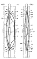
- tool 10 is a casing collar locator tool having a mandrel 12 containing a detection coil 15.
- the magnets 22 are shown symmetrically about the centerline 29 of the arms 20, this centerline also passing through the center of the coil 15 as further described below.
- the respective longitudinally displaced arm ends 30U and 30L are pivotally connected at 32 to respective longitudinally or axially displaceable collars 35U and 35L.
- the collars 35 are axially moveable along the mandrel 12 in response to radial extension and retraction of the outrigger arms 20 (cf. Figs. 1 and 2).
- all the arms share a common collar 30U at the upper ends and a common collar 30L at the lower ends.
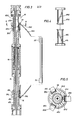
- each collar has an inwardly depending cam 40U and 40L, respectively.
- cams are captured in respective cam races 45U and 45L in translational cam members 47U and 47L which are rigidly secured to the mandrel 12.
- the races in the cam members 47U and L in the preferred embodiment, have identical slopes of opposite hands relative to each other (ef. Fig. 4). The slopes are also constant in this embodiment, thereby producing equal arm/mandrel rotations for equal axial extensions of the arm ends as the respective cams 40U and 40L move through their corresponding races 45U and 45L.
- the arms 20A-20C are also sufficiently transversely stiff to resist twisting spirally about the tool 10 during radial extension and retraction of the arms. Instead, the arms remain axially extended and aligned such that their ends, and the collars connected thereto, rotate about the tool substantially in unison. This synchronizes the end rotations of the arms and produces, for each radial extension thereof, a predetermined rotated arm end position for each end thereof.
- the particular axial movements of the arms are a function of the axial displacements of the ends thereof. Since these are controlled by the cam races, the axial displacements of the arms are in fact a defined result of the corresponding radial extensions thereof. (In practice, of course, the tool is more likely to rotate than the arms, as illustrated in Figs. I and 2, due to the friction of the arms on the walls of the borehole or casing.)
- cam races in the,preferred embodiment have constant, equal, and oppositely handed slopes, it is not necessary that they be equal, constant, or of opposite hands.
- the slope (with respect to the tool axis) of cam race 40U should be twice that of race 40L to prevent axial displacement of the centerline of the magnets as the effective diameter of the arms is changed.
- changes in the radial distance of the arms from the tool would cause the arm ends to move the cams 40U and L through the races 45U and L, resulting in relative rotation of the arms with respect to the tool 10.
Landscapes
- Life Sciences & Earth Sciences (AREA)
- Engineering & Computer Science (AREA)
- Geology (AREA)
- Physics & Mathematics (AREA)
- Mining & Mineral Resources (AREA)
- General Life Sciences & Earth Sciences (AREA)
- Environmental & Geological Engineering (AREA)
- Fluid Mechanics (AREA)
- Geochemistry & Mineralogy (AREA)
- Geophysics (AREA)
- Mechanical Engineering (AREA)
- General Physics & Mathematics (AREA)
- Earth Drilling (AREA)
- Drilling Tools (AREA)
- Replacing, Conveying, And Pick-Finding For Filamentary Materials (AREA)
- Automatic Tool Replacement In Machine Tools (AREA)
- A Measuring Device Byusing Mechanical Method (AREA)
Applications Claiming Priority (2)
| Application Number | Priority Date | Filing Date | Title |
|---|---|---|---|
| US403608 | 1982-07-30 | ||
| US06/403,608 US4506219A (en) | 1982-07-30 | 1982-07-30 | Borehole tool outrigger arm displacement control mechanism |
Publications (3)
| Publication Number | Publication Date |
|---|---|
| EP0102274A2 true EP0102274A2 (de) | 1984-03-07 |
| EP0102274A3 EP0102274A3 (en) | 1985-11-27 |
| EP0102274B1 EP0102274B1 (de) | 1988-05-25 |
Family
ID=23596393
Family Applications (1)
| Application Number | Title | Priority Date | Filing Date |
|---|---|---|---|
| EP83401552A Expired EP0102274B1 (de) | 1982-07-30 | 1983-07-28 | Verfahren und Steuermechanismus zum Bewegen von Gelenkarmen |
Country Status (13)
| Country | Link |
|---|---|
| US (1) | US4506219A (de) |
| EP (1) | EP0102274B1 (de) |
| AU (1) | AU563541B2 (de) |
| BR (1) | BR8304074A (de) |
| CA (1) | CA1203747A (de) |
| DE (1) | DE3376756D1 (de) |
| DK (1) | DK347083A (de) |
| EG (1) | EG16062A (de) |
| ES (1) | ES8502203A1 (de) |
| IN (1) | IN161513B (de) |
| MX (1) | MX154064A (de) |
| NO (1) | NO156501C (de) |
| OA (1) | OA07510A (de) |
Cited By (2)
| Publication number | Priority date | Publication date | Assignee | Title |
|---|---|---|---|---|
| GB2178088A (en) * | 1985-07-25 | 1987-02-04 | Gearhart Tesel Ltd | Improvements in downhole tools |
| EP0210758A3 (de) * | 1985-07-25 | 1989-07-26 | C-E Vetco Uk Limited | Vorrichtung, um eine Schwerstange zu schneiden |
Families Citing this family (19)
| Publication number | Priority date | Publication date | Assignee | Title |
|---|---|---|---|---|
| US4926937A (en) * | 1989-06-08 | 1990-05-22 | Western Atlas International, Inc. | Compound linkage-arm assembly for use in bore-hole tools |
| US5053620A (en) * | 1989-12-13 | 1991-10-01 | Schlumberger Technology Corporation | Logging apparatus and method for determining concentrations of subsurface formation elements |
| USH1192H (en) | 1990-10-26 | 1993-06-01 | Exxon Production Research Company | Low-torque centralizer |
| US5358040A (en) * | 1992-07-17 | 1994-10-25 | The Kinley Corporation | Method and apparatus for running a mechanical roller arm centralizer through restricted well pipe |
| DE69417031D1 (de) * | 1994-09-23 | 1999-04-15 | Schlumberger Technology Bv | Verfahren und Vorrichtung für Bohrlochmessungen in unrunden Bohrlöchern |
| US5575333A (en) | 1995-06-07 | 1996-11-19 | Weatherford U.S., Inc. | Centralizer |
| GB2316422A (en) * | 1996-08-24 | 1998-02-25 | Weatherford Lamb | Centralizer |
| DE19929072A1 (de) * | 1999-06-25 | 2000-12-28 | Pii Pipetronix Gmbh | Vorrichtung zur Prüfung von Rohrleitungen aus ferromagnetischen Materialien |
| US8232796B2 (en) | 2010-07-14 | 2012-07-31 | Invodane Engineering Ltd | Conduit sensor device with magnetic shunt and process for modifying a magnetic field |
| US9442126B2 (en) | 2012-07-14 | 2016-09-13 | Invodane Engineering Ltd. | Conduit sensor device propulsion apparatus and process for operating the propulsion apparatus |
| US9625418B2 (en) * | 2012-07-14 | 2017-04-18 | Invodane Engineering Ltd | Conduit sensor device with magnetic shunt and process for modifying a magnetic field |
| FR3008490B1 (fr) * | 2013-07-10 | 2015-08-07 | Snecma | Dispositif pour l'inspection d'une surface d'une piece electriquement conductrice |
| US10113372B2 (en) | 2013-07-30 | 2018-10-30 | Weatherford Technology Holdings, Llc | Centralizer |
| CN103742126B (zh) * | 2014-01-27 | 2016-06-15 | 西安威盛电子科技股份有限公司 | 一种存储式地层压裂管柱位移测量仪 |
| US10280695B2 (en) | 2014-06-27 | 2019-05-07 | Weatherford Technology Holdings, Llc | Centralizer |
| US10161198B2 (en) | 2015-07-08 | 2018-12-25 | Weatherford Technology Holdings, Llc | Centralizer with integrated stop collar |
| US10472952B2 (en) * | 2017-02-22 | 2019-11-12 | Baker Hughes, A Ge Company, Llc | Arrangement and method for deploying downhole tools to locate casing collar using xy magnetometers |
| CN112012673B (zh) * | 2020-10-22 | 2021-01-15 | 胜利油田固邦石油装备有限责任公司 | 一种定向井套管扶正器 |
| US12116850B1 (en) * | 2023-11-15 | 2024-10-15 | Petromac Ip Limited | Device for centering a sensor assembly in a bore |
Family Cites Families (7)
| Publication number | Priority date | Publication date | Assignee | Title |
|---|---|---|---|---|
| US2258052A (en) * | 1940-01-15 | 1941-10-07 | Jesse E Hall | Spiral guide and tubing holder |
| US2688115A (en) * | 1952-10-08 | 1954-08-31 | Standard Oil Dev Co | Open sleeve electrode assembly for well logging |
| FR1352136A (fr) * | 1962-09-21 | 1964-02-14 | Schlumberger Prospection | Perfectionnements aux dispositifs de détection de joints des coffrages de puits de pétrole |
| US3474541A (en) * | 1968-05-27 | 1969-10-28 | Schlumberger Technology Corp | Well-calipering apparatus |
| US3789966A (en) * | 1971-03-31 | 1974-02-05 | Bendix Corp | Self-adjusting electromagnetic disc clutch |
| US3940689A (en) * | 1974-05-14 | 1976-02-24 | Schlumberger Technology Corporation | Combined eddy current and leakage field detector for well bore piping using a unique magnetizer core structure |
| US3973181A (en) * | 1974-12-19 | 1976-08-03 | Schlumberger Technology Corporation | High frequency method and apparatus for electrical investigation of subsurface earth formations surrounding a borehole containing an electrically non-conductive fluid |
-
1982
- 1982-07-30 US US06/403,608 patent/US4506219A/en not_active Expired - Lifetime
-
1983
- 1983-07-13 NO NO832544A patent/NO156501C/no unknown
- 1983-07-28 EP EP83401552A patent/EP0102274B1/de not_active Expired
- 1983-07-28 DE DE8383401552T patent/DE3376756D1/de not_active Expired
- 1983-07-28 DK DK347083A patent/DK347083A/da not_active Application Discontinuation
- 1983-07-29 AU AU17449/83A patent/AU563541B2/en not_active Ceased
- 1983-07-29 CA CA000433653A patent/CA1203747A/en not_active Expired
- 1983-07-29 ES ES524588A patent/ES8502203A1/es not_active Expired
- 1983-07-29 BR BR8304074A patent/BR8304074A/pt unknown
- 1983-07-29 OA OA58077A patent/OA07510A/xx unknown
- 1983-07-29 MX MX198229A patent/MX154064A/es unknown
- 1983-07-30 EG EG463/83A patent/EG16062A/xx active
- 1983-07-30 IN IN953/CAL/83A patent/IN161513B/en unknown
Cited By (3)
| Publication number | Priority date | Publication date | Assignee | Title |
|---|---|---|---|---|
| GB2178088A (en) * | 1985-07-25 | 1987-02-04 | Gearhart Tesel Ltd | Improvements in downhole tools |
| US4715440A (en) * | 1985-07-25 | 1987-12-29 | Gearhart Tesel Limited | Downhole tools |
| EP0210758A3 (de) * | 1985-07-25 | 1989-07-26 | C-E Vetco Uk Limited | Vorrichtung, um eine Schwerstange zu schneiden |
Also Published As
| Publication number | Publication date |
|---|---|
| EG16062A (en) | 1987-03-30 |
| CA1203747A (en) | 1986-04-29 |
| AU563541B2 (en) | 1987-07-16 |
| EP0102274B1 (de) | 1988-05-25 |
| DK347083A (da) | 1984-01-31 |
| DE3376756D1 (en) | 1988-06-30 |
| US4506219A (en) | 1985-03-19 |
| ES524588A0 (es) | 1984-12-16 |
| NO832544L (no) | 1984-01-31 |
| NO156501C (no) | 1987-09-30 |
| ES8502203A1 (es) | 1984-12-16 |
| AU1744983A (en) | 1984-02-02 |
| OA07510A (en) | 1985-03-31 |
| DK347083D0 (da) | 1983-07-28 |
| EP0102274A3 (en) | 1985-11-27 |
| NO156501B (no) | 1987-06-22 |
| IN161513B (de) | 1987-12-19 |
| MX154064A (es) | 1987-04-20 |
| BR8304074A (pt) | 1984-03-07 |
Similar Documents
| Publication | Publication Date | Title |
|---|---|---|
| EP0102274B1 (de) | Verfahren und Steuermechanismus zum Bewegen von Gelenkarmen | |
| GB2173533A (en) | Centralising down-well location sensor | |
| GB2388137A (en) | Expander device | |
| US2232360A (en) | Apparatus for surveying boreholes | |
| US4776397A (en) | Tool for lowering into centered position within a well bore | |
| FR2366210A1 (fr) | Machine pour fabriquer des tubes renforces par des fils | |
| US3964553A (en) | Borehole tool orienting apparatus and systems | |
| US6003597A (en) | Directional coupling sensor for ensuring complete perforation of a wellbore casing | |
| DE3328261A1 (de) | Verfahren zum erfassen der rotation des gehaeuses eines bohrlochmessinstruments relativ zu einer bezugslage und messwertumformer dafuer | |
| CA2985342C (en) | Antennas for wellbore logging tools and methods of manufacture | |
| US5180021A (en) | Orientable stabilizer | |
| US4244424A (en) | Magnetic casing depth marker | |
| AU2015400159A1 (en) | Antennas for wellbore logging tools and methods of manufacture | |
| CA3067838C (en) | Sensor bracket system and method for a downhole tool | |
| GB1501683A (en) | Borehole apparatus having cambered leaf springs for positioning the apparatus in the borehole | |
| JPH0417279B2 (de) | ||
| CN206516422U (zh) | 一种线缆定心导线装置 | |
| US3112627A (en) | Cylindrical mount for photographic objectives | |
| US2251040A (en) | Means for measuring rotation of apparatus within drill pipe or the like | |
| EP0019825B1 (de) | Bandführungsvorrichtung für Video-Bandaufzeichnungsgerät des Drehkopftyps | |
| US20180363448A1 (en) | Sensor deployment system and method | |
| US3552731A (en) | Apparatus | |
| WO2022204402A1 (en) | Orientation ring | |
| EP0210758A2 (de) | Vorrichtung, um eine Schwerstange zu schneiden | |
| SU1765027A1 (ru) | Прибор дл огибани кривых конических сечений |
Legal Events
| Date | Code | Title | Description |
|---|---|---|---|
| PUAI | Public reference made under article 153(3) epc to a published international application that has entered the european phase |
Free format text: ORIGINAL CODE: 0009012 |
|
| AK | Designated contracting states |
Designated state(s): DE FR GB IT NL |
|
| PUAL | Search report despatched |
Free format text: ORIGINAL CODE: 0009013 |
|
| AK | Designated contracting states |
Designated state(s): DE FR GB IT NL |
|
| 17P | Request for examination filed |
Effective date: 19860412 |
|
| 17Q | First examination report despatched |
Effective date: 19870813 |
|
| GRAA | (expected) grant |
Free format text: ORIGINAL CODE: 0009210 |
|
| ITF | It: translation for a ep patent filed | ||
| AK | Designated contracting states |
Kind code of ref document: B1 Designated state(s): DE FR GB IT NL |
|
| REF | Corresponds to: |
Ref document number: 3376756 Country of ref document: DE Date of ref document: 19880630 |
|
| ET | Fr: translation filed | ||
| PLBE | No opposition filed within time limit |
Free format text: ORIGINAL CODE: 0009261 |
|
| STAA | Information on the status of an ep patent application or granted ep patent |
Free format text: STATUS: NO OPPOSITION FILED WITHIN TIME LIMIT |
|
| 26N | No opposition filed | ||
| ITTA | It: last paid annual fee | ||
| PGFP | Annual fee paid to national office [announced via postgrant information from national office to epo] |
Ref country code: NL Payment date: 19920731 Year of fee payment: 10 |
|
| PGFP | Annual fee paid to national office [announced via postgrant information from national office to epo] |
Ref country code: DE Payment date: 19920910 Year of fee payment: 10 |
|
| PG25 | Lapsed in a contracting state [announced via postgrant information from national office to epo] |
Ref country code: NL Effective date: 19940201 |
|
| NLV4 | Nl: lapsed or anulled due to non-payment of the annual fee | ||
| PG25 | Lapsed in a contracting state [announced via postgrant information from national office to epo] |
Ref country code: DE Effective date: 19940401 |
|
| PGFP | Annual fee paid to national office [announced via postgrant information from national office to epo] |
Ref country code: FR Payment date: 19960711 Year of fee payment: 14 |
|
| PG25 | Lapsed in a contracting state [announced via postgrant information from national office to epo] |
Ref country code: FR Free format text: LAPSE BECAUSE OF NON-PAYMENT OF DUE FEES Effective date: 19980331 |
|
| REG | Reference to a national code |
Ref country code: FR Ref legal event code: ST |
|
| REG | Reference to a national code |
Ref country code: GB Ref legal event code: IF02 |
|
| PGFP | Annual fee paid to national office [announced via postgrant information from national office to epo] |
Ref country code: GB Payment date: 20020724 Year of fee payment: 20 |
|
| PG25 | Lapsed in a contracting state [announced via postgrant information from national office to epo] |
Ref country code: GB Free format text: LAPSE BECAUSE OF EXPIRATION OF PROTECTION Effective date: 20030727 |
|
| REG | Reference to a national code |
Ref country code: GB Ref legal event code: PE20 |