EP0102238A1 - Method for converting radiographic images - Google Patents
Method for converting radiographic images Download PDFInfo
- Publication number
- EP0102238A1 EP0102238A1 EP83304903A EP83304903A EP0102238A1 EP 0102238 A1 EP0102238 A1 EP 0102238A1 EP 83304903 A EP83304903 A EP 83304903A EP 83304903 A EP83304903 A EP 83304903A EP 0102238 A1 EP0102238 A1 EP 0102238A1
- Authority
- EP
- European Patent Office
- Prior art keywords
- phosphor
- light
- image
- stimulating
- ray
- Prior art date
- Legal status (The legal status is an assumption and is not a legal conclusion. Google has not performed a legal analysis and makes no representation as to the accuracy of the status listed.)
- Granted
Links
- 238000000034 method Methods 0.000 title claims abstract description 53
- OAICVXFJPJFONN-UHFFFAOYSA-N Phosphorus Chemical compound [P] OAICVXFJPJFONN-UHFFFAOYSA-N 0.000 claims abstract description 79
- 230000005855 radiation Effects 0.000 claims abstract description 27
- 230000004936 stimulating effect Effects 0.000 claims abstract description 24
- 229910052693 Europium Inorganic materials 0.000 claims description 4
- 229910052771 Terbium Inorganic materials 0.000 claims description 3
- 239000012190 activator Substances 0.000 claims description 3
- 229910052793 cadmium Inorganic materials 0.000 claims description 3
- 229910052689 Holmium Inorganic materials 0.000 claims description 2
- 229910052779 Neodymium Inorganic materials 0.000 claims description 2
- 229910052769 Ytterbium Inorganic materials 0.000 claims description 2
- 229910052788 barium Inorganic materials 0.000 claims description 2
- 229910052794 bromium Inorganic materials 0.000 claims description 2
- 229910052791 calcium Inorganic materials 0.000 claims description 2
- 229910052801 chlorine Inorganic materials 0.000 claims description 2
- 229910052731 fluorine Inorganic materials 0.000 claims description 2
- 229910052740 iodine Inorganic materials 0.000 claims description 2
- 229910052749 magnesium Inorganic materials 0.000 claims description 2
- 229910052748 manganese Inorganic materials 0.000 claims description 2
- 229910052712 strontium Inorganic materials 0.000 claims description 2
- 229910052716 thallium Inorganic materials 0.000 claims description 2
- 229910052718 tin Inorganic materials 0.000 claims description 2
- 229910052725 zinc Inorganic materials 0.000 claims description 2
- 238000006243 chemical reaction Methods 0.000 abstract description 22
- 230000000638 stimulation Effects 0.000 abstract description 6
- 239000000203 mixture Substances 0.000 abstract description 4
- 229910019142 PO4 Inorganic materials 0.000 abstract 2
- 229910013885 M3(PO4)2 Inorganic materials 0.000 abstract 1
- NBIIXXVUZAFLBC-UHFFFAOYSA-K phosphate Chemical compound [O-]P([O-])([O-])=O NBIIXXVUZAFLBC-UHFFFAOYSA-K 0.000 abstract 1
- 239000010452 phosphate Substances 0.000 abstract 1
- 230000035945 sensitivity Effects 0.000 description 12
- -1 silver halide Chemical class 0.000 description 6
- 239000000758 substrate Substances 0.000 description 5
- 230000005284 excitation Effects 0.000 description 4
- 230000003595 spectral effect Effects 0.000 description 4
- CSCPPACGZOOCGX-UHFFFAOYSA-N Acetone Chemical compound CC(C)=O CSCPPACGZOOCGX-UHFFFAOYSA-N 0.000 description 3
- UXVMQQNJUSDDNG-UHFFFAOYSA-L Calcium chloride Chemical compound [Cl-].[Cl-].[Ca+2] UXVMQQNJUSDDNG-UHFFFAOYSA-L 0.000 description 3
- XEKOWRVHYACXOJ-UHFFFAOYSA-N Ethyl acetate Chemical compound CCOC(C)=O XEKOWRVHYACXOJ-UHFFFAOYSA-N 0.000 description 3
- 239000001110 calcium chloride Substances 0.000 description 3
- 229910001628 calcium chloride Inorganic materials 0.000 description 3
- 229910052761 rare earth metal Inorganic materials 0.000 description 3
- 229910052709 silver Inorganic materials 0.000 description 3
- 239000004332 silver Substances 0.000 description 3
- XKRFYHLGVUSROY-UHFFFAOYSA-N Argon Chemical compound [Ar] XKRFYHLGVUSROY-UHFFFAOYSA-N 0.000 description 2
- VYPSYNLAJGMNEJ-UHFFFAOYSA-N Silicium dioxide Chemical compound O=[Si]=O VYPSYNLAJGMNEJ-UHFFFAOYSA-N 0.000 description 2
- BQCADISMDOOEFD-UHFFFAOYSA-N Silver Chemical compound [Ag] BQCADISMDOOEFD-UHFFFAOYSA-N 0.000 description 2
- 125000004429 atom Chemical group 0.000 description 2
- 230000015572 biosynthetic process Effects 0.000 description 2
- 239000011248 coating agent Substances 0.000 description 2
- 238000000576 coating method Methods 0.000 description 2
- 238000001514 detection method Methods 0.000 description 2
- OGPBJKLSAFTDLK-UHFFFAOYSA-N europium atom Chemical compound [Eu] OGPBJKLSAFTDLK-UHFFFAOYSA-N 0.000 description 2
- 230000002349 favourable effect Effects 0.000 description 2
- 239000011521 glass Substances 0.000 description 2
- 239000011701 zinc Substances 0.000 description 2
- DKPFZGUDAPQIHT-UHFFFAOYSA-N Butyl acetate Natural products CCCCOC(C)=O DKPFZGUDAPQIHT-UHFFFAOYSA-N 0.000 description 1
- 229910002420 LaOCl Inorganic materials 0.000 description 1
- 239000000020 Nitrocellulose Substances 0.000 description 1
- 238000010521 absorption reaction Methods 0.000 description 1
- 229910052784 alkaline earth metal Inorganic materials 0.000 description 1
- 229910052915 alkaline earth metal silicate Inorganic materials 0.000 description 1
- 150000001342 alkaline earth metals Chemical class 0.000 description 1
- 229910052782 aluminium Inorganic materials 0.000 description 1
- XAGFODPZIPBFFR-UHFFFAOYSA-N aluminium Chemical compound [Al] XAGFODPZIPBFFR-UHFFFAOYSA-N 0.000 description 1
- 229910052786 argon Inorganic materials 0.000 description 1
- QKYBEKAEVQPNIN-UHFFFAOYSA-N barium(2+);oxido(oxo)alumane Chemical class [Ba+2].[O-][Al]=O.[O-][Al]=O QKYBEKAEVQPNIN-UHFFFAOYSA-N 0.000 description 1
- 230000005540 biological transmission Effects 0.000 description 1
- 229910052681 coesite Inorganic materials 0.000 description 1
- 238000007796 conventional method Methods 0.000 description 1
- 229910052906 cristobalite Inorganic materials 0.000 description 1
- 238000010586 diagram Methods 0.000 description 1
- 238000001035 drying Methods 0.000 description 1
- 238000000295 emission spectrum Methods 0.000 description 1
- 238000005562 fading Methods 0.000 description 1
- 229910052736 halogen Inorganic materials 0.000 description 1
- 125000005843 halogen group Chemical group 0.000 description 1
- FUZZWVXGSFPDMH-UHFFFAOYSA-N hexanoic acid Chemical compound CCCCCC(O)=O FUZZWVXGSFPDMH-UHFFFAOYSA-N 0.000 description 1
- 238000007689 inspection Methods 0.000 description 1
- 238000011835 investigation Methods 0.000 description 1
- 150000002603 lanthanum Chemical class 0.000 description 1
- 239000000463 material Substances 0.000 description 1
- 229910052751 metal Inorganic materials 0.000 description 1
- 239000002184 metal Substances 0.000 description 1
- 229920001220 nitrocellulos Polymers 0.000 description 1
- 229920000139 polyethylene terephthalate Polymers 0.000 description 1
- 239000005020 polyethylene terephthalate Substances 0.000 description 1
- 238000001454 recorded image Methods 0.000 description 1
- 238000009877 rendering Methods 0.000 description 1
- 239000010979 ruby Substances 0.000 description 1
- 229910001750 ruby Inorganic materials 0.000 description 1
- 239000004065 semiconductor Substances 0.000 description 1
- 239000000377 silicon dioxide Substances 0.000 description 1
- 239000002904 solvent Substances 0.000 description 1
- 238000001228 spectrum Methods 0.000 description 1
- 229910052682 stishovite Inorganic materials 0.000 description 1
- 238000002834 transmittance Methods 0.000 description 1
- 229910052905 tridymite Inorganic materials 0.000 description 1
- 229910052984 zinc sulfide Inorganic materials 0.000 description 1
Images

Classifications
-
- G—PHYSICS
- G03—PHOTOGRAPHY; CINEMATOGRAPHY; ANALOGOUS TECHNIQUES USING WAVES OTHER THAN OPTICAL WAVES; ELECTROGRAPHY; HOLOGRAPHY
- G03C—PHOTOSENSITIVE MATERIALS FOR PHOTOGRAPHIC PURPOSES; PHOTOGRAPHIC PROCESSES, e.g. CINE, X-RAY, COLOUR, STEREO-PHOTOGRAPHIC PROCESSES; AUXILIARY PROCESSES IN PHOTOGRAPHY
- G03C5/00—Photographic processes or agents therefor; Regeneration of such processing agents
- G03C5/16—X-ray, infrared, or ultraviolet ray processes
-
- C—CHEMISTRY; METALLURGY
- C09—DYES; PAINTS; POLISHES; NATURAL RESINS; ADHESIVES; COMPOSITIONS NOT OTHERWISE PROVIDED FOR; APPLICATIONS OF MATERIALS NOT OTHERWISE PROVIDED FOR
- C09K—MATERIALS FOR MISCELLANEOUS APPLICATIONS, NOT PROVIDED FOR ELSEWHERE
- C09K11/00—Luminescent, e.g. electroluminescent, chemiluminescent materials
- C09K11/08—Luminescent, e.g. electroluminescent, chemiluminescent materials containing inorganic luminescent materials
- C09K11/70—Luminescent, e.g. electroluminescent, chemiluminescent materials containing inorganic luminescent materials containing phosphorus
- C09K11/72—Luminescent, e.g. electroluminescent, chemiluminescent materials containing inorganic luminescent materials containing phosphorus also containing halogen, e.g. halophosphates
- C09K11/722—Chalcogenides
-
- C—CHEMISTRY; METALLURGY
- C09—DYES; PAINTS; POLISHES; NATURAL RESINS; ADHESIVES; COMPOSITIONS NOT OTHERWISE PROVIDED FOR; APPLICATIONS OF MATERIALS NOT OTHERWISE PROVIDED FOR
- C09K—MATERIALS FOR MISCELLANEOUS APPLICATIONS, NOT PROVIDED FOR ELSEWHERE
- C09K11/00—Luminescent, e.g. electroluminescent, chemiluminescent materials
- C09K11/08—Luminescent, e.g. electroluminescent, chemiluminescent materials containing inorganic luminescent materials
- C09K11/70—Luminescent, e.g. electroluminescent, chemiluminescent materials containing inorganic luminescent materials containing phosphorus
- C09K11/72—Luminescent, e.g. electroluminescent, chemiluminescent materials containing inorganic luminescent materials containing phosphorus also containing halogen, e.g. halophosphates
- C09K11/73—Luminescent, e.g. electroluminescent, chemiluminescent materials containing inorganic luminescent materials containing phosphorus also containing halogen, e.g. halophosphates also containing alkaline earth metals
-
- C—CHEMISTRY; METALLURGY
- C09—DYES; PAINTS; POLISHES; NATURAL RESINS; ADHESIVES; COMPOSITIONS NOT OTHERWISE PROVIDED FOR; APPLICATIONS OF MATERIALS NOT OTHERWISE PROVIDED FOR
- C09K—MATERIALS FOR MISCELLANEOUS APPLICATIONS, NOT PROVIDED FOR ELSEWHERE
- C09K11/00—Luminescent, e.g. electroluminescent, chemiluminescent materials
- C09K11/08—Luminescent, e.g. electroluminescent, chemiluminescent materials containing inorganic luminescent materials
- C09K11/77—Luminescent, e.g. electroluminescent, chemiluminescent materials containing inorganic luminescent materials containing rare earth metals
- C09K11/7709—Phosphates
- C09K11/771—Phosphates with alkaline earth metals
- C09K11/7711—Phosphates with alkaline earth metals with halogens
-
- G—PHYSICS
- G21—NUCLEAR PHYSICS; NUCLEAR ENGINEERING
- G21K—TECHNIQUES FOR HANDLING PARTICLES OR IONISING RADIATION NOT OTHERWISE PROVIDED FOR; IRRADIATION DEVICES; GAMMA RAY OR X-RAY MICROSCOPES
- G21K4/00—Conversion screens for the conversion of the spatial distribution of X-rays or particle radiation into visible images, e.g. fluoroscopic screens
Definitions
- the present invention relates to a method for converting radiographic images, and more particularly to a method for the converting radiographic images which utilizes a stimulable phosphor.
- thermoluminescent phosphor layer a radiation that has passed through an object to thereby store therein a radiation energy pattern corresponding to the pattern of the radiation, and after that the thermoluminescent phosphor layer is heated to take out the stored radiation energy in the form of a light signal pattern, the light pattern forming an image.
- thermoluminescent phosphor layer and the support which are the components of the panel.
- thermoluminescent phosphor layer and the support which are the components of the panel.
- thermoluminescent phosphor as the phosphor
- thermal energy as the excitation energy.
- other methods which use at least one of visible rays and infrared rays as the excitation energy as described in U.S. Patent No.3,359,527, and Japanese Patent O.P.I. Publication Nos.12142/ 1980, 12143/1980, 12144/1980, 12145/1980, 84389/1980, 160078/ 1980, and the like.
- cerium-and samarium-activated strontium sulfide phosphor (SrS:Ce,Sm) europium- and samarium-activated strontium sulfide phosphor (SrS:Eu,Sm), europium- and samarium-activated lanthanum oxysulfide phosphor (La 2 0 2 S:Eu,Sm), manganese- and halogen- activated zinccadmium sulfide phosphor [(Zn,Cd)S:Mn,X wherein X is a halogen], europium-activated barium aluminate phosphor, alkaline earth metal silicate phosphor, rare earth element-activated lanthanum oxyhalide phosphor, and the like, are extremely low sensitive, so that from the practical application point of view, the improvement on the improvement on the improvement on the improvement on the improvement on the improvement on the improvement on the improvement on the improvement on the improvement on the improvement
- An object of the present invention is to provide a method for converting radiographic images which has an extremely high sensitivity and which is practically usable, and another object of the invention is to provide a method for converting radiographic images which has a high response speed to a stimulating light and a high speed of reading out a radiographic image.
- the method for converting radiographic images in the present invention comprises the absorption of a radiation passed through an object into at least one of those phosphate-type phosphors having the above-described formula; the stimulation of the phosphor by at least one of visible rays having long wavelengths not less than 500nm and infrared rays to thereby release as fluorescence the radiation energy that has been >stored in the phosphor; and the detection of the fluorescence.
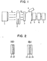
- FIG. 1 The method for converting radiographic imagesjof the present invention is illustrated in detail below by use of the schematic illustration shown in Figure 1.
- 11 is a radiation source
- 12 is an object
- 13 is a radiographic image conversion panel having a visible ray- or infrared ray-stimulable phosphor layer containing a phosphor having Formula (I) or (n:)
- 14 is a stimulation light source for radiating as fluorescence the radiographic image on the radiographic image conversion panel
- 15 is a photoelectric converter for the detection of the fluorescence radiated from the radiographic image conversion panel
- 16 is a reproduction device reproducing as an image the photoelectrically converted signal detected by photoelectric converter
- 17 is a display unit displaying the reproduced image
- 18 is a filter for cutting the reflected light from light source 14 and for transmitting only the light radiated from radiographic image conversion panel 13.
- object 12 is put in between radiation source 11 and radiographic image conversion panel 13, and when a radiation R irradiates, the radiation R passes through the object according to the radiation transmittance of each part of the object, and the transmitted image RI (i.e., the image formed according to the intensity.pattern of the radiation) is then made incident upon radiographic image conversion panel 13.
- the transmitted image RI i.e., the image formed according to the intensity.pattern of the radiation
- This incident transmission image RI is absorbed into the phosphor layer of panel 13, whereby electrons or positive holes proportional to the radiation dose absorbed in the phosphor layer are produced to be stored in the trap levels of the phosphor, that is, such a stored image as a latent image of the radiation-transmitted image is formed.
- the stored image is then stimulated by a light energy to become actualized.
- electromagnetic wave which is at least one of visible rays having wavelengths of not less than 500nm and infrared rays from light source 14 irradiates the phosphor layer to expel the electrons or positive holes stored in the trap thereof to radiate the stored image in the form of fluorescence.
- the intensity pattern of this radiated fluorescence is proportional to the intensity pattern of the radiation energy absorbed into the phosphor layer of panel 13, and the light signal is converted into an electric signal by means of photoelectric converter 15 such as, for example, a photoelectric multiplier, etc., and reproduced into an image by image reproduction device 16, and the image is then displayed on image display unit 17.
- photoelectric converter 15 such as, for example, a photoelectric multiplier, etc.
- radiographic image conversion panel and the stimulation light source to radiate the stored image as fluorescence used in the method of the present invention are illustrated in detail below:
- the following is an example of the method for preparing a radiographic image conversion panel.
- a phosphor and one part by weight of nitrocellulose are mixed with a mixture of solvents (a mixture of acetone, ethyl acetate and butyl acetate) to prepare a coating liguid having a viscosity of about 50 centistokes.
- This coating liguid is then coated uniformly over a polyethylene terephthalate film (substrate) which is held horizontal, and, as it is, allowed to stand over a whole day and night for drying, thereby forming a phosphor layer with a thickness of about 300pm to produce a radiographic image conversion panel.
- a transparent glass or a metallic thin plate such as of aluminum may also be used.
- the panel may be of such a structure that, as shown in Figure 2(b), the phosphor is sandwiched in between substrates 23 and 24 such as two glass plates to make an arbitrary " thickness-having phosphor layer 22 whose periphery is sealed.
- the stimulating light source besides the light source emitting a light having a band spectral distribution in at least one of infrared region and visible rays' region of from not less than 500nm to preferably not more than 1100nm, there may be used a light source emitting a single wavelength light such as He-Ne laser light (633nm), YAG laser light (1064nm), ruby laser light (694nm), argon laser light, semiconductor laser light, and the like. Particularly when using a laser light, a high stimulation energy can be obtained.
- a light source emitting a single wavelength light such as He-Ne laser light (633nm), YAG laser light (1064nm), ruby laser light (694nm), argon laser light, semiconductor laser light, and the like.
- a high stimulation energy can be obtained.
- Figure 3 is a drawing showing the relation of stimulated emission to stimulating light's wavelength of the radiographic image conversion panel in the present invention; that is, it -plots the respective intensity of the fluorescence radiated when the 3Sr 3 (PO 4 ) 2 ⁇ CaCl 2 :Eu phosphor using-panel is subjected to various light different in the wavelength after irradiated by X-rays having an equivoltage of 80KVp.
- the excitable wavelength range of stimulating light is from 500 to 1100nm, and particularly the range, of : from 500 to 900nm is the optimum wavelength range. Therefore, as may be understood. from the above, the excitable wavelength range of stimulating light of the phosphate-type phosphor usable in the present invention, although differing to some extent according to the composition of the phosphor used, may be within the range of approximately from 500 to 1100nm, and the optimum wavelength range is from 500 to 900nm.
- the stimulating light source for use in releasing as fluorescence the radiation energy that is stored in the phosphor layer at least one of visible rays having wavelengths of not less than 500nm and infrared rays can be used.
- the traps stimulated by infrared rays have small energy gaps and therefore the periods for trapping electrons or positive holes are short, so that it is not considered favorable for practical use to read out the information of such traps.
- the phosphor layer of the irradiated radiographic image conversion panel is stimulated by scanning with infrared rays to radiate a light and the light is then electrically treated, but the over- s all scanning of the entire area of the phosphor layer requires a certain period of time, so that even if the same radiation dose is applied, there is the possibility that there occurs a difference between the initial readout value and the final readout value.
- the phosphate-type phosphor having Formula (I) or (II) for use in the method of the present invention, it is desirable to use one having large energy gap trap which is efficiently stimulated by a higher energy light, i.e., a light whose wavelengths are as short as possible.
- the optimum stimulating light's wavelength range of the phosphate-type phosphor of the present invention is in the range of from 500 to 900nm, so that the phosphor has little fading phenomenon as well as high storability of the radiographic image.
- the fluorescence that is radiated from the phosphor layer is desirable to have the spectral distribution thereof in a region of as much short wavelengths as possible for the reason that when stimulating the phosphor layer with a light energy, it is necessary to separate the reflected light of the stimulating light from the fluorescence emitted from the phosphor layer, and the photoelectric converter that receives the fluorescence radiated from the phosphor layer generally becomes more highly sensitive to a short wavelength light energy of not less than-600nm, and the phosphor used in the method of the present invention satisfies this condition.
- any of the phosphate-type phosphors usable in the present invention emits a light having its peak in the region of not more than 600nm, and the light is easily separated from a stimulating light and well coincident with the spectral sensitivity of the light receiver so that the light is highly efficiently received, and consequently the sensitivity of the image receiving system can be increased.
- Figure 4 shows an example of the spectrum distribution of the light emitted from the 3Sr 3 (PO 4 ) 2 ⁇ CaCl 2 :Eu phosphor when stimulated by He-Ne laser light after the phosphor is irradiated by X-rays of an equivoltage of 80KVp.
- Table 1 shows the comparison between the sensitivities obtained by the method of the present invention and the sensitivities obtained by the method of the prior art using the SrS:Eu,Sm phosphor, BaO.SiO 2 :Ce phosphor and LaOCl: Ce,Tb phosphor.
- the sensitivity is expressed in terms of the luminous intensity in the case where the radiographic image conversion panel is irradiated by X-rays having a tube . voltage of 80KVp, and then stimulated by He-Ne laser light, and the fluorescence radiated from the phosphor layer is received by a light receiver (a photoelectric multiplier having a spectral sensitivity of S-5).
- a light receiver a photoelectric multiplier having a spectral sensitivity of S-5.
- the . obtained sensitivities are shown with relative values when the sensitivity of the SrS:Eu,Sm phosphor is regarded as 1.
- Figure 5 is a drawing relating to the response speed of the method of the present invention.
- the figure shows the comparison between the response speed of the method of the present invention at the time of the irradiation by Ne-He laser light whose intensity changes in the form of a rectangular wave as shown with the broken line in the figure and the response speed of the method of the prior art which uses BaFCl:Eu phosphor.
- the response speed of the method of the present invention (B) is significantly higher than that of the method of the prior art (A), so that the method of the present invention enables to largely increase the readout speed of radiographic images.
- the method for converting radiographic images in the present invention is a method so improved as to have a remarkably high sensitivity and high readout speed.
Abstract
Description
- The present invention relates to a method for converting radiographic images, and more particularly to a method for the converting radiographic images which utilizes a stimulable phosphor.
- Description of the state of the art In order to obtain radiographic images, there has until now been used silver halide-utilizing photographic system, the so-called radiographic photography, but in recent years there has arised a demand for the development of method for the formation of radiographic images without use of a silver halide because of the global shortage of silver resources.
- As a method substitutable for the above-mentioned radiographic photography, there has now been contemplated such a method that the radiation that has passed through an object is absorbed into a phosphor, and after that, the phosphor is excited by a certain energy to thereby radiate the radiation energy stored in the phosphor as fluorescence, and the fluorescence is then detected to thereby form an image. To be concrete, there is proposed a method for the converting radiographic images wherein as the phosphor, a thermoluminescent phosphor j is used, and as the excitation energy, thermal energy is used (British Patent No.1,462,769 and Japanese Patent Publication Open to Public Inspection (hereinafter referred to as Japanese. Patent O.P.I. Publication) No.29889/1976). This conversion method is such that a panel comprising a support formed thereon with a thermoluminescent phosphor layer is used, and into the thermoluminescent phosphor layer of the panel is absorbed a radiation that has passed through an object to thereby store therein a radiation energy pattern corresponding to the pattern of the radiation, and after that the thermoluminescent phosphor layer is heated to take out the stored radiation energy in the form of a light signal pattern, the light pattern forming an image. However, it is indispensable for this method that the panel is so heat-resistant as not to be deformed nor to be changed in quality by heat because it must be -heated at the time of changing the stored radiation energy into-a light signal, and therefore large restrictions are put on the materials used for the thermoluminescent phosphor layer and the support which are the components of the panel. Thus, there exists a large drawback in the practical use of the method which uses a thermoluminescent phosphor as the phosphor and thermal energy as the excitation energy. On the other hand, there are also'known other methods which use at least one of visible rays and infrared rays as the excitation energy as described in U.S. Patent No.3,359,527, and Japanese Patent O.P.I. Publication Nos.12142/ 1980, 12143/1980, 12144/1980, 12145/1980, 84389/1980, 160078/ 1980, and the like.
- These methods need not be heated at the time of changing the stored radiation energy into a light signal unlike the previously mentioned method, and therefore the panel need not be heat-resistant, so that the methods may be deemed favorable for the conversion of radiographic images.
- However, among those phosphors used in the methods disclosed in the above-mentioned pulications, for example, cerium-and samarium-activated strontium sulfide phosphor (SrS:Ce,Sm) europium- and samarium-activated strontium sulfide phosphor (SrS:Eu,Sm), europium- and samarium-activated lanthanum oxysulfide phosphor (La202S:Eu,Sm), manganese- and halogen- activated zinccadmium sulfide phosphor [(Zn,Cd)S:Mn,X wherein X is a halogen], europium-activated barium aluminate phosphor, alkaline earth metal silicate phosphor, rare earth element-activated lanthanum oxyhalide phosphor, and the like, are extremely low sensitive, so that from the practical application point of view, the improvement on the sensitivity in the formation of radiographic images had been sought. Further, among those phosphors used in the above methods, copper- and lead- activated zinc sulfide phosphor (ZnS:Cu,Pb), europium-activated alkaline earth fluorohalide phosphor, rare earth element-activated alkaline earth metal fluorohalide-type phosphor, rare earth element-activated divalent metal fluorohalide phosphor, and the like, have extremely low response speed to the excitation light that is used for releasing the stored radiation energy as fluorescence (hereinafter referred to as "stimulating ray or light", and therefore they have the disadvantage that the speed thereof to read out the image recorded in the phospho becomes extremely reduced.
- An object of the present invention is to provide a method for converting radiographic images which has an extremely high sensitivity and which is practically usable, and another object of the invention is to provide a method for converting radiographic images which has a high response speed to a stimulating light and a high speed of reading out a radiographic image.
- As a result of our various investigations it has been found that the above objects can be accomplished by a method for converting radiographic images comprising steps of
- 1) making a radiation passed through an object absorbed into a stimulable phosphor,
- 2) stimulating the phosphor by a stimulating ray to release a radiation energy stored in the phospher as fluorescence, and
- 3) detecting the fluorescence to form an image, wherein the phosphor is a phosphate-type phosphor of Formula (I) or (II) and the stimulating ray is at least one of a visible ray of not less than 500nm and a infrared ray.


- The method for converting radiographic images in the present invention comprises the absorption of a radiation passed through an object into at least one of those phosphate-type phosphors having the above-described formula; the stimulation of the phosphor by at least one of visible rays having long wavelengths not less than 500nm and infrared rays to thereby release as fluorescence the radiation energy that has been >stored in the phosphor; and the detection of the fluorescence.
-
- Figure 1 is a block diagram of the method of the present invention, illustrating that an radiographic image is recorded onto a phosphor and the recorded image is stimulated by an stimulating ray to read the image.
- Figure 2(a) and 2(b) are sectional views respectively showing a radiographic image conversion panel, and inter alia,
- Figure 2(a) shows a phosphoric layer which is provided to a substrate, and Figure 2(b) shows the phosphoric layer which is provided between two substrates.
- Figure 3 is a graph showing the relation of stimulated emission to stimulating light's wavelength of the radiographic image conversion panel..relating to the invention.
- Figure 4 is a graph showing an stimulated emission spectrum obtained when a 3Sr3(PO4)2·CaCl2: Eu phosphor is stimulated by a He-Ne laser after irradiated by an X-ray.
- Figure 5 is a graph showing the response speeds to the stimulation respectively applied in the radiographic image conversion methods, and in which the method of the invention (B) is compared with the conventional method (A).
- The method for converting radiographic imagesjof the present invention is illustrated in detail below by use of the schematic illustration shown in Figure 1. In Figure 1, numbered 11 is a radiation source, 12 is an object, 13 is a radiographic image conversion panel having a visible ray- or infrared ray-stimulable phosphor layer containing a phosphor having Formula (I) or (n:), 14 is a stimulation light source for radiating as fluorescence the radiographic image on the radiographic image conversion panel, 15 is a photoelectric converter for the detection of the fluorescence radiated from the radiographic image conversion panel, 16 is a reproduction device reproducing as an image the photoelectrically converted signal detected by
photoelectric converter 15, 17 is a display unit displaying the reproduced image, and 18 is a filter for cutting the reflected light from light source 14 and for transmitting only the light radiated from radiographic image conversion panel 13. 15 and these numbered thereafter are allowed to be any if capable of reproducing the light information from 13 into an image in some form, and not necessarily limited to the above. As shown in Figure 1, object 12 is put in between radiation source 11 and radiographic image conversion panel 13, and when a radiation R irradiates, the radiation R passes through the object according to the radiation transmittance of each part of the object, and the transmitted image RI (i.e., the image formed according to the intensity.pattern of the radiation) is then made incident upon radiographic image conversion panel 13. This incident transmission image RI is absorbed into the phosphor layer of panel 13, whereby electrons or positive holes proportional to the radiation dose absorbed in the phosphor layer are produced to be stored in the trap levels of the phosphor, that is, such a stored image as a latent image of the radiation-transmitted image is formed. The stored image is then stimulated by a light energy to become actualized. Namely, electromagnetic wave which is at least one of visible rays having wavelengths of not less than 500nm and infrared rays from light source 14 irradiates the phosphor layer to expel the electrons or positive holes stored in the trap thereof to radiate the stored image in the form of fluorescence. The intensity pattern of this radiated fluorescence is proportional to the intensity pattern of the radiation energy absorbed into the phosphor layer of panel 13, and the light signal is converted into an electric signal by means ofphotoelectric converter 15 such as, for example, a photoelectric multiplier, etc., and reproduced into an image by image reproduction device 16, and the image is then displayed on image display unit 17. - The radiographic image conversion panel and the stimulation light source to radiate the stored image as fluorescence . used in the method of the present invention are illustrated in detail below:
- The structure of the radiographic image conversion panel, as shown in-Figure 2(a), is composed of a
support 21 and aphosphor layer 22 formed on one side ofsupport 21. Thisphosphor layer 22 comprises at least one of phosphors included in those phosphate-type phosphors having the foregoing formula. The phosphor used herein, when stimulated by electromagnetic wave which is at least one of visible rays having wavelengths of not less than 500nm and infrared rays after being subjected to the irradiation of radiation, emits a strong stimulated light, which can be used in the method of the present invention, and particularly when the activator content of the phosphor is 0 to 1 gram atom, preferably from 10-6 to 0.6 gram atom to the unit quantity of the host lattice of the phosphor, the stimulated light intensity becomes extremely strong, and by rendering these the phosphor layer of the radiographic image conversion panel, a particularly highly efficient radiographic image conversion can be carried out. - The following is an example of the method for preparing a radiographic image conversion panel.
- First, eight parts by weight of a phosphor and one part by weight of nitrocellulose are mixed with a mixture of solvents (a mixture of acetone, ethyl acetate and butyl acetate) to prepare a coating liguid having a viscosity of about 50 centistokes. This coating liguid is then coated uniformly over a polyethylene terephthalate film (substrate) which is held horizontal, and, as it is, allowed to stand over a whole day and night for drying, thereby forming a phosphor layer with a thickness of about 300pm to produce a radiographic image conversion panel. In this case, as the substrate, for example, a transparent glass or a metallic thin plate such as of aluminum may also be used.
- In addition, the panel may be of such a structure that, as shown in Figure 2(b), the phosphor is sandwiched in between
substrates phosphor layer 22 whose periphery is sealed. - In the method of the present invention, as the stimulating light source, besides the light source emitting a light having a band spectral distribution in at least one of infrared region and visible rays' region of from not less than 500nm to preferably not more than 1100nm, there may be used a light source emitting a single wavelength light such as He-Ne laser light (633nm), YAG laser light (1064nm), ruby laser light (694nm), argon laser light, semiconductor laser light, and the like. Particularly when using a laser light, a high stimulation energy can be obtained.
- Figure 3 is a drawing showing the relation of stimulated emission to stimulating light's wavelength of the radiographic image conversion panel in the present invention; that is, it -plots the respective intensity of the fluorescence radiated when the 3Sr3(PO4)2·CaCl2:Eu phosphor using-panel is subjected to various light different in the wavelength after irradiated by X-rays having an equivoltage of 80KVp.
- As apparent from Figure 3, in the case of the 3Sr3(PO4)2· CaC12:Eu phosphor, the excitable wavelength range of stimulating light is from 500 to 1100nm, and particularly the range, of : from 500 to 900nm is the optimum wavelength range. Therefore, as may be understood. from the above, the excitable wavelength range of stimulating light of the phosphate-type phosphor usable in the present invention, although differing to some extent according to the composition of the phosphor used, may be within the range of approximately from 500 to 1100nm, and the optimum wavelength range is from 500 to 900nm.
- In the method of the present invention, as the stimulating light source for use in releasing as fluorescence the radiation energy that is stored in the phosphor layer, at least one of visible rays having wavelengths of not less than 500nm and infrared rays can be used. However, the traps stimulated by infrared rays have small energy gaps and therefore the periods for trapping electrons or positive holes are short, so that it is not considered favorable for practical use to read out the information of such traps. For example, in obtaining an image, there is often carried out such a procedure that the phosphor layer of the irradiated radiographic image conversion panel .is stimulated by scanning with infrared rays to radiate a light and the light is then electrically treated, but the over- s all scanning of the entire area of the phosphor layer requires a certain period of time, so that even if the same radiation dose is applied, there is the possibility that there occurs a difference between the initial readout value and the final readout value.
- Also because of this, as the phosphate-type phosphor, having Formula (I) or (II) for use in the method of the present invention, it is desirable to use one having large energy gap trap which is efficiently stimulated by a higher energy light, i.e., a light whose wavelengths are as short as possible. As described above, the optimum stimulating light's wavelength range of the phosphate-type phosphor of the present invention is in the range of from 500 to 900nm, so that the phosphor has little fading phenomenon as well as high storability of the radiographic image.
- In the method of the present invention, the fluorescence that is radiated from the phosphor layer is desirable to have the spectral distribution thereof in a region of as much short wavelengths as possible for the reason that when stimulating the phosphor layer with a light energy, it is necessary to separate the reflected light of the stimulating light from the fluorescence emitted from the phosphor layer, and the photoelectric converter that receives the fluorescence radiated from the phosphor layer generally becomes more highly sensitive to a short wavelength light energy of not less than-600nm, and the phosphor used in the method of the present invention satisfies this condition.
- Namely, any of the phosphate-type phosphors usable in the present invention emits a light having its peak in the region of not more than 600nm, and the light is easily separated from a stimulating light and well coincident with the spectral sensitivity of the light receiver so that the light is highly efficiently received, and consequently the sensitivity of the image receiving system can be increased.
- Figure 4 shows an example of the spectrum distribution of the light emitted from the 3Sr3(PO4)2·CaCl2:Eu phosphor when stimulated by He-Ne laser light after the phosphor is irradiated by X-rays of an equivoltage of 80KVp.
- The following Table 1 shows the comparison between the sensitivities obtained by the method of the present invention and the sensitivities obtained by the method of the prior art using the SrS:Eu,Sm phosphor, BaO.SiO2:Ce phosphor and LaOCl: Ce,Tb phosphor.
- In the table, the sensitivity is expressed in terms of the luminous intensity in the case where the radiographic image conversion panel is irradiated by X-rays having a tube . voltage of 80KVp, and then stimulated by He-Ne laser light, and the fluorescence radiated from the phosphor layer is received by a light receiver (a photoelectric multiplier having a spectral sensitivity of S-5). In the table, the . obtained sensitivities are shown with relative values when the sensitivity of the SrS:Eu,Sm phosphor is regarded as 1.

- As apparent from Table 1, the method for the conversion of radiographic images in the present invention (No.4-No.16) has remarkably higher sensitivities than does the method of the prior art (No.1-No.3).
- Figure 5 is a drawing relating to the response speed of the method of the present invention. The figure shows the comparison between the response speed of the method of the present invention at the time of the irradiation by Ne-He laser light whose intensity changes in the form of a rectangular wave as shown with the broken line in the figure and the response speed of the method of the prior art which uses BaFCl:Eu phosphor.
- As apparent from Figure 5, the response speed of the method of the present invention (B) is significantly higher than that of the method of the prior art (A), so that the method of the present invention enables to largely increase the readout speed of radiographic images.
- As has been described in detail, the method for converting radiographic images in the present invention is a method so improved as to have a remarkably high sensitivity and high readout speed.
Claims (7)

Applications Claiming Priority (2)
| Application Number | Priority Date | Filing Date | Title |
|---|---|---|---|
| JP148285/82 | 1982-08-25 | ||
| JP57148285A JPS5938278A (en) | 1982-08-25 | 1982-08-25 | Conversion of radiation image |
Publications (2)
| Publication Number | Publication Date |
|---|---|
| EP0102238A1 true EP0102238A1 (en) | 1984-03-07 |
| EP0102238B1 EP0102238B1 (en) | 1986-06-04 |
Family
ID=15449343
Family Applications (1)
| Application Number | Title | Priority Date | Filing Date |
|---|---|---|---|
| EP83304903A Expired EP0102238B1 (en) | 1982-08-25 | 1983-08-24 | Method for converting radiographic images |
Country Status (4)
| Country | Link |
|---|---|
| US (1) | US4507379A (en) |
| EP (1) | EP0102238B1 (en) |
| JP (1) | JPS5938278A (en) |
| DE (1) | DE3363936D1 (en) |
Families Citing this family (19)
| Publication number | Priority date | Publication date | Assignee | Title |
|---|---|---|---|---|
| JPS6087565A (en) * | 1983-10-19 | 1985-05-17 | Fuji Photo Film Co Ltd | Picture scanning reading method |
| JPS60135929A (en) * | 1983-12-23 | 1985-07-19 | Konishiroku Photo Ind Co Ltd | Reading method of radiation picture |
| DE3477082D1 (en) * | 1984-05-21 | 1989-04-13 | Siemens Ag | Registration screen for radiation images |
| US4665003A (en) * | 1984-07-31 | 1987-05-12 | Fuji Photo Film Co., Ltd. | Stimulable phosphor sheet and method of conveying the same |
| US5028509A (en) * | 1984-09-14 | 1991-07-02 | Konica Corporation | Method for converting radiographic image, radiation energy storage panel having stimulable phosphor-containing layer and alkali halide phosphor |
| US4785183A (en) * | 1985-09-18 | 1988-11-15 | Konishiroku Photo Industry Co., Ltd. | Method for reading radiation image information |
| JP2707354B2 (en) * | 1990-04-18 | 1998-01-28 | 富士写真フイルム株式会社 | Radiation image reader |
| JP3016630B2 (en) * | 1991-07-01 | 2000-03-06 | コニカ株式会社 | Radiation image recording and reading device |
| DE69300721T2 (en) * | 1992-06-10 | 1996-05-30 | Agfa Gevaert Nv | Photo-stimulable storage phosphor and its use in radiography. |
| EP1017062A3 (en) | 1998-12-28 | 2001-10-04 | Fuji Photo Film Co., Ltd. | Radiation image conversion panel and method of manufacturing radiation image conversion panel |
| JP2003248097A (en) | 2002-02-25 | 2003-09-05 | Konica Corp | Radiation image conversion panel and its production method |
| US7927316B2 (en) | 2002-04-26 | 2011-04-19 | Millipore Corporation | Disposable, sterile fluid transfer device |
| JP2006300647A (en) | 2005-04-19 | 2006-11-02 | Fuji Photo Film Co Ltd | Phosphor panel manufacturing method |
| JP2008164339A (en) | 2006-12-27 | 2008-07-17 | Konica Minolta Medical & Graphic Inc | Radiological image conversion panel |
| JP2008185568A (en) | 2007-01-31 | 2008-08-14 | Fujifilm Corp | Radiological image conversion panel |
| SG153002A1 (en) | 2007-11-16 | 2009-06-29 | Millipore Corp | Fluid transfer device |
| FR2940440B1 (en) | 2008-12-18 | 2010-12-24 | Millipore Corp | DEVICE FOR TRANSFERRING A MEDIUM |
| CN107422334A (en) * | 2017-09-01 | 2017-12-01 | 中恩光电科技(苏州)有限公司 | A kind of device of laser measurement target speed |
| CN112391168A (en) * | 2020-11-18 | 2021-02-23 | 青岛科技大学 | Novel luminescent adjustable fluorescent powder and preparation method thereof |
Citations (8)
| Publication number | Priority date | Publication date | Assignee | Title |
|---|---|---|---|---|
| GB582122A (en) * | 1941-04-10 | 1946-11-06 | Gen Electric Co Ltd | Improvements in luminescent materials |
| FR1161720A (en) * | 1955-07-22 | 1958-09-03 | Thorn Electrical Ind Ltd | Improvements in luminescent materials and their manufacturing processes |
| FR1186938A (en) * | 1956-04-10 | 1959-09-03 | Westinghouse Electric Corp | Luminescent material |
| FR1492357A (en) * | 1966-07-29 | 1967-08-18 | Philips Nv | Process for preparing an alkaline earth halophosphate |
| US3509065A (en) * | 1968-06-25 | 1970-04-28 | Gen Telephone & Elect | Method of making alkaline earth phosphate phosphors |
| US3513346A (en) * | 1965-06-30 | 1970-05-19 | Mitsubishi Electric Corp | Phosphors and process of producing the same |
| FR1598628A (en) * | 1967-12-22 | 1970-07-06 | ||
| US3609094A (en) * | 1968-10-15 | 1971-09-28 | Sylvania Electric Prod | Ytterbium-activated strontium phosphate phosphors |
Family Cites Families (4)
| Publication number | Priority date | Publication date | Assignee | Title |
|---|---|---|---|---|
| US3513103A (en) * | 1967-12-12 | 1970-05-19 | Sylvania Electric Prod | Fluorescent phosphor |
| US3859527A (en) * | 1973-01-02 | 1975-01-07 | Eastman Kodak Co | Apparatus and method for producing images corresponding to patterns of high energy radiation |
| GB1462769A (en) * | 1973-10-12 | 1977-01-26 | Kodak Ltd | Methods of producing luminescent images |
| JPS5611392A (en) * | 1979-07-11 | 1981-02-04 | Fuji Photo Film Co Ltd | Method and device for converting radiation image |
-
1982
- 1982-08-25 JP JP57148285A patent/JPS5938278A/en active Granted
-
1983
- 1983-08-22 US US06/525,318 patent/US4507379A/en not_active Expired - Lifetime
- 1983-08-24 EP EP83304903A patent/EP0102238B1/en not_active Expired
- 1983-08-24 DE DE8383304903T patent/DE3363936D1/en not_active Expired
Patent Citations (8)
| Publication number | Priority date | Publication date | Assignee | Title |
|---|---|---|---|---|
| GB582122A (en) * | 1941-04-10 | 1946-11-06 | Gen Electric Co Ltd | Improvements in luminescent materials |
| FR1161720A (en) * | 1955-07-22 | 1958-09-03 | Thorn Electrical Ind Ltd | Improvements in luminescent materials and their manufacturing processes |
| FR1186938A (en) * | 1956-04-10 | 1959-09-03 | Westinghouse Electric Corp | Luminescent material |
| US3513346A (en) * | 1965-06-30 | 1970-05-19 | Mitsubishi Electric Corp | Phosphors and process of producing the same |
| FR1492357A (en) * | 1966-07-29 | 1967-08-18 | Philips Nv | Process for preparing an alkaline earth halophosphate |
| FR1598628A (en) * | 1967-12-22 | 1970-07-06 | ||
| US3509065A (en) * | 1968-06-25 | 1970-04-28 | Gen Telephone & Elect | Method of making alkaline earth phosphate phosphors |
| US3609094A (en) * | 1968-10-15 | 1971-09-28 | Sylvania Electric Prod | Ytterbium-activated strontium phosphate phosphors |
Also Published As
| Publication number | Publication date |
|---|---|
| JPH0261996B2 (en) | 1990-12-21 |
| US4507379A (en) | 1985-03-26 |
| EP0102238B1 (en) | 1986-06-04 |
| JPS5938278A (en) | 1984-03-02 |
| DE3363936D1 (en) | 1986-07-10 |
Similar Documents
| Publication | Publication Date | Title |
|---|---|---|
| EP0102238B1 (en) | Method for converting radiographic images | |
| US4239968A (en) | Method and apparatus for recording and reproducing a radiation image | |
| EP0022564B1 (en) | Method of and apparatus for obtaining a radiation image by use of a stimulable phosphor | |
| US4236078A (en) | Method and apparatus for recording and reproducing a radiation image | |
| US4661419A (en) | Phosphor and radiation image storage panel containing the same | |
| JPS5944339B2 (en) | Radiographic image conversion method | |
| US4585944A (en) | Radiation image storage panel | |
| JPH0159567B2 (en) | ||
| EP0142734B1 (en) | Radiation image recording and reproducing method | |
| JPS609542B2 (en) | Radiographic image conversion method | |
| EP0092240B1 (en) | Radiation image storage panel | |
| EP0111892B1 (en) | Radiation image recording and reproducing method | |
| EP0083085B1 (en) | Radiation image recording and reproducing method | |
| EP0111893B2 (en) | Radiation image recording and reproducing method | |
| US4948696A (en) | Radiation image recording and reproducing method | |
| US4931652A (en) | Radiation image recording and reproducing method | |
| EP0136588B1 (en) | Radiation image recording and reproducing method | |
| US4605861A (en) | Radiation image recording and reproducing method | |
| JPH058237B2 (en) | ||
| US4891277A (en) | Phosphor, and radiation image storage panel | |
| JPH0550719B2 (en) | ||
| EP0163144B1 (en) | Phosphor, radiation image recording and reproducing method and radiation image storage panel | |
| JPS6249318B2 (en) | ||
| JPS61241385A (en) | Radiation image conversion panel | |
| JPS58201883A (en) | Radiation image conversion |
Legal Events
| Date | Code | Title | Description |
|---|---|---|---|
| PUAI | Public reference made under article 153(3) epc to a published international application that has entered the european phase |
Free format text: ORIGINAL CODE: 0009012 |
|
| AK | Designated contracting states |
Designated state(s): DE FR GB |
|
| 17P | Request for examination filed |
Effective date: 19840808 |
|
| GRAA | (expected) grant |
Free format text: ORIGINAL CODE: 0009210 |
|
| AK | Designated contracting states |
Kind code of ref document: B1 Designated state(s): DE FR GB |
|
| REF | Corresponds to: |
Ref document number: 3363936 Country of ref document: DE Date of ref document: 19860710 |
|
| ET | Fr: translation filed | ||
| PLBE | No opposition filed within time limit |
Free format text: ORIGINAL CODE: 0009261 |
|
| STAA | Information on the status of an ep patent application or granted ep patent |
Free format text: STATUS: NO OPPOSITION FILED WITHIN TIME LIMIT |
|
| 26N | No opposition filed | ||
| PGFP | Annual fee paid to national office [announced via postgrant information from national office to epo] |
Ref country code: FR Payment date: 19970811 Year of fee payment: 15 |
|
| PGFP | Annual fee paid to national office [announced via postgrant information from national office to epo] |
Ref country code: GB Payment date: 19970815 Year of fee payment: 15 |
|
| PG25 | Lapsed in a contracting state [announced via postgrant information from national office to epo] |
Ref country code: GB Free format text: LAPSE BECAUSE OF NON-PAYMENT OF DUE FEES Effective date: 19980824 |
|
| PGFP | Annual fee paid to national office [announced via postgrant information from national office to epo] |
Ref country code: DE Payment date: 19980831 Year of fee payment: 16 |
|
| GBPC | Gb: european patent ceased through non-payment of renewal fee |
Effective date: 19980824 |
|
| PG25 | Lapsed in a contracting state [announced via postgrant information from national office to epo] |
Ref country code: FR Free format text: LAPSE BECAUSE OF NON-PAYMENT OF DUE FEES Effective date: 19990430 |
|
| REG | Reference to a national code |
Ref country code: FR Ref legal event code: ST |
|
| PG25 | Lapsed in a contracting state [announced via postgrant information from national office to epo] |
Ref country code: DE Free format text: LAPSE BECAUSE OF NON-PAYMENT OF DUE FEES Effective date: 20000601 |