EP0102135A2 - Vereinfachte Montage einer Gleitschutzkette - Google Patents
Vereinfachte Montage einer Gleitschutzkette Download PDFInfo
- Publication number
- EP0102135A2 EP0102135A2 EP83301405A EP83301405A EP0102135A2 EP 0102135 A2 EP0102135 A2 EP 0102135A2 EP 83301405 A EP83301405 A EP 83301405A EP 83301405 A EP83301405 A EP 83301405A EP 0102135 A2 EP0102135 A2 EP 0102135A2
- Authority
- EP
- European Patent Office
- Prior art keywords
- rope
- loop
- link
- loops
- connector
- Prior art date
- Legal status (The legal status is an assumption and is not a legal conclusion. Google has not performed a legal analysis and makes no representation as to the accuracy of the status listed.)
- Granted
Links
- 239000002184 metal Substances 0.000 claims abstract description 6
- 229910052751 metal Inorganic materials 0.000 claims abstract description 6
- 238000000034 method Methods 0.000 claims description 8
- 239000004743 Polypropylene Substances 0.000 claims description 3
- 239000000463 material Substances 0.000 claims description 3
- -1 polypropylene Polymers 0.000 claims description 3
- 229920001155 polypropylene Polymers 0.000 claims description 3
- 229920003002 synthetic resin Polymers 0.000 claims description 3
- 239000000057 synthetic resin Substances 0.000 claims description 3
- 229920001169 thermoplastic Polymers 0.000 claims description 3
- 239000004416 thermosoftening plastic Substances 0.000 claims description 3
- XEEYBQQBJWHFJM-UHFFFAOYSA-N Iron Chemical compound [Fe] XEEYBQQBJWHFJM-UHFFFAOYSA-N 0.000 description 4
- 230000008569 process Effects 0.000 description 4
- 238000010438 heat treatment Methods 0.000 description 3
- 230000004048 modification Effects 0.000 description 3
- 238000012986 modification Methods 0.000 description 3
- 239000000835 fiber Substances 0.000 description 2
- 229910052742 iron Inorganic materials 0.000 description 2
- 238000005476 soldering Methods 0.000 description 2
- 229910000831 Steel Inorganic materials 0.000 description 1
- 230000008901 benefit Effects 0.000 description 1
- 230000008859 change Effects 0.000 description 1
- 238000010276 construction Methods 0.000 description 1
- 230000006872 improvement Effects 0.000 description 1
- 238000003780 insertion Methods 0.000 description 1
- 230000037431 insertion Effects 0.000 description 1
- 239000010959 steel Substances 0.000 description 1
Images


Classifications
-
- B—PERFORMING OPERATIONS; TRANSPORTING
- B60—VEHICLES IN GENERAL
- B60C—VEHICLE TYRES; TYRE INFLATION; TYRE CHANGING; CONNECTING VALVES TO INFLATABLE ELASTIC BODIES IN GENERAL; DEVICES OR ARRANGEMENTS RELATED TO TYRES
- B60C27/00—Non-skid devices temporarily attachable to resilient tyres or resiliently-tyred wheels
- B60C27/06—Non-skid devices temporarily attachable to resilient tyres or resiliently-tyred wheels extending over the complete circumference of the tread, e.g. made of chains or cables
- B60C27/10—Non-skid devices temporarily attachable to resilient tyres or resiliently-tyred wheels extending over the complete circumference of the tread, e.g. made of chains or cables having tensioning means
-
- Y—GENERAL TAGGING OF NEW TECHNOLOGICAL DEVELOPMENTS; GENERAL TAGGING OF CROSS-SECTIONAL TECHNOLOGIES SPANNING OVER SEVERAL SECTIONS OF THE IPC; TECHNICAL SUBJECTS COVERED BY FORMER USPC CROSS-REFERENCE ART COLLECTIONS [XRACs] AND DIGESTS
- Y10—TECHNICAL SUBJECTS COVERED BY FORMER USPC
- Y10T—TECHNICAL SUBJECTS COVERED BY FORMER US CLASSIFICATION
- Y10T29/00—Metal working
- Y10T29/49—Method of mechanical manufacture
- Y10T29/49826—Assembling or joining
- Y10T29/49863—Assembling or joining with prestressing of part
- Y10T29/49874—Prestressing rod, filament or strand
-
- Y—GENERAL TAGGING OF NEW TECHNOLOGICAL DEVELOPMENTS; GENERAL TAGGING OF CROSS-SECTIONAL TECHNOLOGIES SPANNING OVER SEVERAL SECTIONS OF THE IPC; TECHNICAL SUBJECTS COVERED BY FORMER USPC CROSS-REFERENCE ART COLLECTIONS [XRACs] AND DIGESTS
- Y10—TECHNICAL SUBJECTS COVERED BY FORMER USPC
- Y10T—TECHNICAL SUBJECTS COVERED BY FORMER US CLASSIFICATION
- Y10T29/00—Metal working
- Y10T29/49—Method of mechanical manufacture
- Y10T29/49826—Assembling or joining
- Y10T29/49908—Joining by deforming
- Y10T29/49915—Overedge assembling of seated part
-
- Y—GENERAL TAGGING OF NEW TECHNOLOGICAL DEVELOPMENTS; GENERAL TAGGING OF CROSS-SECTIONAL TECHNOLOGIES SPANNING OVER SEVERAL SECTIONS OF THE IPC; TECHNICAL SUBJECTS COVERED BY FORMER USPC CROSS-REFERENCE ART COLLECTIONS [XRACs] AND DIGESTS
- Y10—TECHNICAL SUBJECTS COVERED BY FORMER USPC
- Y10T—TECHNICAL SUBJECTS COVERED BY FORMER US CLASSIFICATION
- Y10T29/00—Metal working
- Y10T29/49—Method of mechanical manufacture
- Y10T29/49826—Assembling or joining
- Y10T29/49908—Joining by deforming
- Y10T29/49925—Inward deformation of aperture or hollow body wall
Definitions
- the invention particularly relates to new and novel tire chain structures of the type having non-metallic interconnectors for the cross chains.
- One of the major problems in all tire chain structures is to provide for case of adjustment in the size of the tire chain structure to exactly fit a particular tire, without requiring an infinite number of different sizes to fit all of the different tire sizes.
- Another closely related problem is that of tightening the tire chain structure after it is assembled upon the tire.
- an adjustable size tire chain structure comprising a plurality of metal cross chains, an inboard rope connector for interconnection with the inboard ends of said cross chains, an outboard rope connector for interconnection with the outboard ends of said cross chains, a combined rope to cross chain connecting link and rope clamping ring and rope connector adjustment device provided at each end of each cross chain for connection to said inboard and outboard rope connectors, each of said connecting links comprising a substantially V-shaped wire body with a loop formed at each end of the V , said wire body being connected to the associated cross chain end by linking through the end link at the bottom of the V, said loops each being engaged with the associated one of said rope connectors by at least partially surrounding.the rope connector, at least one of said loops being dimensioned and arranged to partially surround and slidably engage said rope, at least one of said slidably engaged loops being open sufficiently to permit the rope to be slipped out of and into said loop, at least one collar clamped to said rope at a position upon said rope in the vicinity
- FIG. 1 is a view of the tire 8 from the outboard side.
- a connecting link 16 is provided at each end of each cross chain 10 for connection to the inboard and outboard rope connectors 12 and 14.
- The. connecting link 16 is really a combined rope to cross chain connecting link and rope clamping ring and rope connection adjustment device, as will appear from the following detailed description.
- the connecting links 16 are each connected to an associated end link 11 of the cross chains 10 by threading through the end link 11.
- each of the inboard and outboard rope connectors are provided with metal wire interconnection hooks 18 and 20 to enable these ends to be interconnected as the chain structure is assembled upon the tire 8.
- a spreader rope 22 is connected around the outboard rope connector 14 to provide a final tightening of the outboard rope connector 14, and to thereby tighten the entire chain structure.
- the spreader rope 22 is preferably interconnected with the outboard rope connector 14 by means of spreader hooks 24, with at least one spreader hook 24 being connected to each segment of the outboard rope connector 14 between adjacent connecting links 16. As shown in the drawing, two spreader hooks may preferably be provided on the opposite sides of the interconnection hooks 18 and 20, although that is not essential.
- the tightening provided by the spreader rope 22 tightens the entire structure so that no spreader rope is required for the inboard rope connector 12.
- the spreader rope 22 is provided with end hooks 26 at each end, and an intermediate connector hook 28.
- the spreader rope 22 is arranged circumferentially around the outboard rope connector, and one of the spreader end hooks 26 is connected to the intermediate connector hook 28.
- the other end of the spreader rope 22 is tightened by means of a locking ring 30 associated with the intermediate connector hook 28 by pulling the spreader rope tightly through the intermediate connector hook 28 and the locking ring 30.
- the loose end of the spreader rope 22 may then be connected diagonally across the array formed by the rope connector 14 and the spreader rope 22, as shown at 33, and doubled back, as shown at 35, with the spreader end hook 26 connected to one of the spreader hooks 24, or to the body of the spreader, to maintain the entire assembly in a tight condition.
- FIG. 2 is an enlarged detail view of the connecting link 16, showing how that connecting link is attached to the end link 11, and illustrating how the connecting link is attached to the outboard rope connector 14.
- the structure is exactly the same for the interconnection of the connecting links 16 to the inboard rope connector 12.
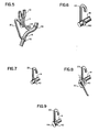
- FIGS. 3, 4, and 5 all illustrate different aspects of the connecting link 16 and its relationship to the rope connector 14.
- the connecting link 16 is in the form of a substantially V-shaped wire body with individual loops 32 and 34 formed at the respective ends of the V.
- the mid-portion of the V - is engaged with the end link 11 of the associated cross chain 10.
- the V is inverted.
- Each of the end loops 32 and 34 is formed in a plane substantially perpendicular to the plane of the V.
- the plane of the V is substantially parallel to the plane of the surface of the paper, and the planes of the loops 32 and 34 are substantially perpendicular to the plane of the paper.
- the loops 32 and 34 are arranged to engage and embrace the rope connector 14 by at least partially surrounding the rope of the rope connector. Loop 32 is securely clamped to the rope connector 14 so as to prevent any movement or sliding of the rope 14 through loop 32.
- loop 32 preferably substantially completely surrounds the body of the rope 14.
- a collar ring 36 is tightly fixed to the body of the rope, as illustrated in each of the FIGS. 2, 3, 4, and 5.
- Collar 36 may simply consist of an open wire ring which is securely clamped to the body of the rope 14.
- the rope connector 14 When the rope connector 14 is to be shortened, the rope connector is gathered into a loop, as indicated at 38, and the body of the rope connector is then slipped into the loop 34 with the collar 36 on the inside of the loop 34 of the connecting link 16, as illustrated in FIG. 2.
- the collar 36 prevents the body of the rope connector 14 from sliding through the loop 34, thus maintaining the rope loop 38.
- the rope loop 38 cannot be released by sliding the body of the rope connector 14 through loop 32 because the body of rope 14 is tightly clamped by loop 32 to prevent any sliding motion.
- the body of the rope 14 is slipped out of the opening of loop 34 by an upward movement, the rope loop 38 is straightened out, and the body of the rope connector 14 is again inserted into the loop 34, as shown in FIG. 3.
- the rope connector 14 is lengthened by the amount of rope released by the release of loop 38. This operation is further illustrated in the perspective view of FIG. 4, where the rope connector 14 is shown in full after release from the loop 34, and is shown in phantom after reinsertion into the loop 34. Since the body of the rope 14 is slidably engaged within the loop 34, any tendency of the rope to retain the rope loop 38 is overcome by the longitudinal tension on the rope connector 14.
- the process can be reversed.
- the rope body can be slipped out of the loop 34, as shown in FIG. 4, and then the rope body may be slipped back into the loop 34 with the collar 36 inside the loop 34, as pictured in FIG. 2.
- the collar 36 is clamped to the rope at a position upon the rope on the side of the slidably engaged loop 34 opposite to the side of the firmly clamped loop 32 when the rope is stretched from the clamped loop to the collar.
- the collar 36 is sufficiently large to prevent the rope from sliding through the slidably engaged loop 34 when the rope is placed into the slidably engaged loop 34 with the collar 36 on the side of the slidably engaged loop 34 facing the clamped loop 32. This maintains the rope loop 38 between the clamped loop 32 and the slidably engaged loop 34 to thereby shorten the rope connector.
- FIG. 5 illustrates another major feature and advantage of the structure of the connecting link 16.
- the end of the connecting link 16 including the loop 34 may be threaded in and out of the end link 11 of the cross chain 10 to permit the cross chain 10 to be replaced with a new chain, or to reverse the cross chain 10 to distribute the wear upon the cross chain. This can be easily accomplished without the necessity for the use of any tools.
- a heated implement such as a soldering iron 42 is then forcefully applied to the end of the thermoplastic rope 14, fusing the ends of the fibers of the rope together, and upsetting and enlarging the end of the rope so as to make it impossible for the end of the rope to slip out of the clamp loop 40.
- the attachment of the connecting links to the inboard and outboard rope connectors is carried out by inserting the body of the rope connector into loop 32 of each of the associated connecting links, with the associated connecting links substantially equally spaced along each rope connector. Loop 32 is then firmly closed on each connecting link to firmly clamp the rope within that loop. The separate collar 36 is then clamped at a position upon each rope connector adjacent to each connecting link on the side of the unclamped loop 34 facing away from the clamped loop 32.
- the collars 46 and 36A are sometimes referred to below as outer collars, and the collar 48 as a middle collar.
- the connecting link 16A may first be connected-to the end link 11 of the cross chain, and then connected to the appropriate section of the rope 14A.
- one of the loops 32A may be con- nected to the rope 14A, and then the other side of the connecting link 16A can be threaded through the end link 11 of the cross chain, and then fastened to the rope 14A.
Landscapes
- Engineering & Computer Science (AREA)
- Mechanical Engineering (AREA)
- Ropes Or Cables (AREA)
Applications Claiming Priority (2)
| Application Number | Priority Date | Filing Date | Title |
|---|---|---|---|
| US06/410,416 US4392521A (en) | 1981-10-28 | 1982-08-23 | Simplified adjustable tire chain |
| US410416 | 1982-08-23 |
Publications (3)
| Publication Number | Publication Date |
|---|---|
| EP0102135A2 true EP0102135A2 (de) | 1984-03-07 |
| EP0102135A3 EP0102135A3 (en) | 1985-11-21 |
| EP0102135B1 EP0102135B1 (de) | 1988-08-17 |
Family
ID=23624622
Family Applications (1)
| Application Number | Title | Priority Date | Filing Date |
|---|---|---|---|
| EP83301405A Expired EP0102135B1 (de) | 1982-08-23 | 1983-03-15 | Vereinfachte Montage einer Gleitschutzkette |
Country Status (3)
| Country | Link |
|---|---|
| US (1) | US4392521A (de) |
| EP (1) | EP0102135B1 (de) |
| DE (1) | DE3377704D1 (de) |
Families Citing this family (6)
| Publication number | Priority date | Publication date | Assignee | Title |
|---|---|---|---|---|
| US5236025A (en) * | 1989-06-08 | 1993-08-17 | Burns Bros., Inc. | Diagonal tire chains with side cable fasteners |
| US5056574A (en) * | 1989-06-08 | 1991-10-15 | Burns Bros., Inc. | Tire chain with cross members forming a zig-zag pattern |
| US5804001A (en) * | 1997-01-03 | 1998-09-08 | Christian Joseph | Snow chains for vehicles |
| US6530406B1 (en) | 2001-09-25 | 2003-03-11 | Michael Gentry | Chain tightening apparatus and method of using the same |
| US8162016B1 (en) * | 2009-11-09 | 2012-04-24 | Le Joe H | Modular tire chain apparatus |
| US9630549B2 (en) | 2014-05-23 | 2017-04-25 | René ROY | Multi point attachment tie-downs of EPDM materials |
Family Cites Families (9)
| Publication number | Priority date | Publication date | Assignee | Title |
|---|---|---|---|---|
| US909448A (en) * | 1905-05-31 | 1909-01-12 | W G Nagel Electric Company | Cable-hanger. |
| CH73914A (de) * | 1916-04-04 | 1917-05-01 | Faerberei & Appreturgesellscha | Verfahren zum Erzeugen von Schaumbädern bei beliebiger Temperatur |
| US1295669A (en) * | 1916-07-28 | 1919-02-25 | William D Addison | Chain guard for vehicle-wheels. |
| US1495982A (en) * | 1923-01-23 | 1924-06-03 | Clarence N Blough | Chain fastener |
| FR767887A (de) * | 1937-03-19 | 1934-07-25 | ||
| US2453325A (en) * | 1947-02-28 | 1948-11-09 | Walter F Karstens | Nonskid tire chain |
| BE551554A (de) * | 1955-10-06 | |||
| FR2286720A1 (fr) * | 1974-10-02 | 1976-04-30 | Mongault Jacques | Dispositif antipatinant, amovible et complementaire a tous les types de roues connues des vehicules |
| US4185674A (en) * | 1978-05-31 | 1980-01-29 | Giannone Victor Salvatore | Vehicle tire chain structure |
-
1982
- 1982-08-23 US US06/410,416 patent/US4392521A/en not_active Expired - Fee Related
-
1983
- 1983-03-15 DE DE8383301405T patent/DE3377704D1/de not_active Expired
- 1983-03-15 EP EP83301405A patent/EP0102135B1/de not_active Expired
Also Published As
| Publication number | Publication date |
|---|---|
| DE3377704D1 (en) | 1988-09-22 |
| US4392521A (en) | 1983-07-12 |
| EP0102135B1 (de) | 1988-08-17 |
| EP0102135A3 (en) | 1985-11-21 |
Similar Documents
| Publication | Publication Date | Title |
|---|---|---|
| US4161059A (en) | Method of fastening to a belt | |
| US4392521A (en) | Simplified adjustable tire chain | |
| FI99157C (fi) | Tasapainotusjärjestely pyörivää elintä varten | |
| US3988005A (en) | Load binder and chain assembly | |
| US4556246A (en) | Chain components | |
| GR3000529T3 (en) | Clamping collar | |
| US5330240A (en) | Closed sling with self-cinching loop | |
| EP0111243A1 (de) | Vorrichtung zum Klemmen des geschlitzten Teils einer geschlitzten wärmeschrumpfbaren Muffe | |
| US4959891A (en) | Attachment device for strap end | |
| US5173998A (en) | Grab hook for attachment to a chain to provide partial link adjustment, and method of use thereof | |
| US4431042A (en) | Antiskid tire chain | |
| US2966848A (en) | Expandable base plate | |
| US4051740A (en) | Segmental v belt | |
| EP0120682A1 (de) | Rohrschelle | |
| US20010047573A1 (en) | Bungi-claw | |
| CA2096606C (en) | Elastic cushioning band for motor-vehicle seats | |
| JPH01266341A (ja) | ロープ留金具 | |
| EP0652397B1 (de) | Anschlussvorrichtung, Verfahren und Gerät zu deren Herstellung | |
| JP7767052B2 (ja) | クランプ | |
| GB1579615A (en) | Siebe conveyor belt | |
| CA1233397A (en) | Tire chain | |
| GB2144795A (en) | Pipe clamp | |
| US4039203A (en) | Conical guide for a coupling pin on an agricultural implement | |
| US1266933A (en) | Cable-clamp. | |
| CA2083989C (en) | Grab hook for attachment to a chain to provide partial link adjustment |
Legal Events
| Date | Code | Title | Description |
|---|---|---|---|
| PUAI | Public reference made under article 153(3) epc to a published international application that has entered the european phase |
Free format text: ORIGINAL CODE: 0009012 |
|
| AK | Designated contracting states |
Designated state(s): CH DE FR GB IT LI SE |
|
| PUAL | Search report despatched |
Free format text: ORIGINAL CODE: 0009013 |
|
| AK | Designated contracting states |
Designated state(s): CH DE FR GB IT LI SE |
|
| 17P | Request for examination filed |
Effective date: 19860503 |
|
| 17Q | First examination report despatched |
Effective date: 19870716 |
|
| ITF | It: translation for a ep patent filed | ||
| GRAA | (expected) grant |
Free format text: ORIGINAL CODE: 0009210 |
|
| AK | Designated contracting states |
Kind code of ref document: B1 Designated state(s): CH DE FR GB IT LI SE |
|
| REF | Corresponds to: |
Ref document number: 3377704 Country of ref document: DE Date of ref document: 19880922 |
|
| ET | Fr: translation filed | ||
| PG25 | Lapsed in a contracting state [announced via postgrant information from national office to epo] |
Ref country code: SE Effective date: 19890316 |
|
| ITTA | It: last paid annual fee | ||
| PG25 | Lapsed in a contracting state [announced via postgrant information from national office to epo] |
Ref country code: CH Effective date: 19890331 Ref country code: LI Effective date: 19890331 |
|
| PLBE | No opposition filed within time limit |
Free format text: ORIGINAL CODE: 0009261 |
|
| STAA | Information on the status of an ep patent application or granted ep patent |
Free format text: STATUS: NO OPPOSITION FILED WITHIN TIME LIMIT |
|
| 26N | No opposition filed | ||
| PGFP | Annual fee paid to national office [announced via postgrant information from national office to epo] |
Ref country code: FR Payment date: 19890915 Year of fee payment: 7 |
|
| PGFP | Annual fee paid to national office [announced via postgrant information from national office to epo] |
Ref country code: DE Payment date: 19890920 Year of fee payment: 7 |
|
| PGFP | Annual fee paid to national office [announced via postgrant information from national office to epo] |
Ref country code: GB Payment date: 19890930 Year of fee payment: 7 |
|
| REG | Reference to a national code |
Ref country code: CH Ref legal event code: PL |
|
| PG25 | Lapsed in a contracting state [announced via postgrant information from national office to epo] |
Ref country code: GB Effective date: 19900315 |
|
| GBPC | Gb: european patent ceased through non-payment of renewal fee | ||
| PG25 | Lapsed in a contracting state [announced via postgrant information from national office to epo] |
Ref country code: FR Effective date: 19901130 |
|
| PG25 | Lapsed in a contracting state [announced via postgrant information from national office to epo] |
Ref country code: DE Effective date: 19901201 |
|
| REG | Reference to a national code |
Ref country code: FR Ref legal event code: ST |
|
| EUG | Se: european patent has lapsed |
Ref document number: 83301405.3 Effective date: 19900124 |