EP0100792A2 - Hydraulic device for removing and inserting marine bushings - Google Patents
Hydraulic device for removing and inserting marine bushings Download PDFInfo
- Publication number
- EP0100792A2 EP0100792A2 EP82111383A EP82111383A EP0100792A2 EP 0100792 A2 EP0100792 A2 EP 0100792A2 EP 82111383 A EP82111383 A EP 82111383A EP 82111383 A EP82111383 A EP 82111383A EP 0100792 A2 EP0100792 A2 EP 0100792A2
- Authority
- EP
- European Patent Office
- Prior art keywords
- bushings
- cylinders
- hydraulic
- hydraulic device
- fact
- Prior art date
- Legal status (The legal status is an assumption and is not a legal conclusion. Google has not performed a legal analysis and makes no representation as to the accuracy of the status listed.)
- Granted
Links
- 238000000605 extraction Methods 0.000 description 3
- 238000003780 insertion Methods 0.000 description 2
- 230000037431 insertion Effects 0.000 description 2
- 238000007792 addition Methods 0.000 description 1
- 230000005540 biological transmission Effects 0.000 description 1
- 239000000284 extract Substances 0.000 description 1
- 239000002184 metal Substances 0.000 description 1
- 238000012986 modification Methods 0.000 description 1
- 230000004048 modification Effects 0.000 description 1
- 238000006467 substitution reaction Methods 0.000 description 1
Images


Classifications
-
- B—PERFORMING OPERATIONS; TRANSPORTING
- B25—HAND TOOLS; PORTABLE POWER-DRIVEN TOOLS; MANIPULATORS
- B25B—TOOLS OR BENCH DEVICES NOT OTHERWISE PROVIDED FOR, FOR FASTENING, CONNECTING, DISENGAGING OR HOLDING
- B25B27/00—Hand tools, specially adapted for fitting together or separating parts or objects whether or not involving some deformation, not otherwise provided for
- B25B27/02—Hand tools, specially adapted for fitting together or separating parts or objects whether or not involving some deformation, not otherwise provided for for connecting objects by press fit or detaching same
- B25B27/06—Hand tools, specially adapted for fitting together or separating parts or objects whether or not involving some deformation, not otherwise provided for for connecting objects by press fit or detaching same inserting or withdrawing sleeves or bearing races
- B25B27/064—Hand tools, specially adapted for fitting together or separating parts or objects whether or not involving some deformation, not otherwise provided for for connecting objects by press fit or detaching same inserting or withdrawing sleeves or bearing races fluid driven
-
- B—PERFORMING OPERATIONS; TRANSPORTING
- B25—HAND TOOLS; PORTABLE POWER-DRIVEN TOOLS; MANIPULATORS
- B25B—TOOLS OR BENCH DEVICES NOT OTHERWISE PROVIDED FOR, FOR FASTENING, CONNECTING, DISENGAGING OR HOLDING
- B25B27/00—Hand tools, specially adapted for fitting together or separating parts or objects whether or not involving some deformation, not otherwise provided for
- B25B27/0028—Tools for removing or installing seals
Definitions
- the present invention relates to a hydraulic device by which it is possible to remove and insert marine bushings without need of demounting other components of the transmission on screw propelled boats.
- the device being the subject matter of the present invention may also be used for underwater bushing replacement, thus without being compelled to raise the boat in the dry dock.
- the device may be employed by the divers without the aid of other components and obtaining the very same operative and technical advantage.
- the hydraulic device for removing and inserting marine bushings is characterized by the fact of comprising two lateral and parallel hydraulic cylinders, carrying out an axial thrust extracting said bushings from their seat in the support or inserting said bushings into said seat, as well as two lateral air cylinders parallel to the hydraulic cylinders, carrying out the back thrust to return the device to the inoperative position.
- the device also comprises two self-centering forks provided with inserts for matching the diameter of the shaft and the support. One of the forks moves together with the hydraulic pistons and the other with the rods of said pistons.
- the pistons cause return of the rods, by exerting an axial force that extracts the bushing from its supportor inserts said bushing thereinto.
- the device 1 of the present invention comprises two self-centering forks 2 and 3 for positioning the device on the propeller shaft of the boat; fork 2 is fixed to the rods 4 of two cylinders 5 while fork 3 is fixedly secured to flanges 6 of said cylinders 5.
- two air cylinders 7 are arranged on either side and are fixed to cylinders 5 and to the sliding fork 2.
- the force required for extraction and insertion of the bushings is obtained through a manual hydraulic pump 8 actuating said device by the pressure obtained by acting on the control lever 9.
- gauge blocks 12 and 13 It is also necessary to use the gauge blocks 12 and 13 to carry out the operative matching between the forks of the device and the diameter of the propeller shaft of the boat on which the bushings are to be replaced.
- the device of the present invention After having removed the screw propeller 14 from the shaft 15, the device of the present invention is positioned astride the support 16 with the sliding fork 2 on the side of the screw connection.
- the device of the present invention After having slipped a fresh bushing 22 on the shaft 15, the device of the present invention is so positioned that the sliding fork 2 is between said bushing 22 and the support 16.
- the gauge block On the fixed fork 2 the gauge block is positioned, then pressure is delivered to the cylinders 5, the device abuts on the support 16 and the sliding fork 3 pushes axially the bushing 22 until it is completely inserted into its seat.
- the device of the present invention attains the above mentioned objects and solves in an optimal and practical way the problems relating to the replacement of bushings for driving shafts of screw propellers for boats, and it has to be pointed out that the foregoing detailed description of a preferred embodiment does not limit the scope of the invention, but on the contrary it has to be understood that many modifications, variations, additions or substitutions of elements may be resorted to the parts and structures of the device, without altering however the spirit and the object of the invention or departing from its scope of protection, as it is defined in the appended claims.
Landscapes
- Engineering & Computer Science (AREA)
- Mechanical Engineering (AREA)
- Earth Drilling (AREA)
- Drilling And Exploitation, And Mining Machines And Methods (AREA)
- Mounting Of Bearings Or Others (AREA)
- Automatic Assembly (AREA)
- Support Of The Bearing (AREA)
- Filtration Of Liquid (AREA)
- Clamps And Clips (AREA)
- Hand Tools For Fitting Together And Separating, Or Other Hand Tools (AREA)
Abstract
Description
- The present invention relates to a hydraulic device by which it is possible to remove and insert marine bushings without need of demounting other components of the transmission on screw propelled boats.
- It is indeed well known that removal of marine bushings mounted on supports of shafts for propeller motion, presently faces great difficulties.
- These are due to the presence of supports mounted at non easily accessible positions, the different size related to the shaft, the difficulty of removing the bushings axially without damages to the shaft or the support.
- Sometimes it is also necessary to replace them in spots which are not close to shipyards or dry docks, that can however carry out the entire operation of bushing replacement in a far lower time, so as to attain a considerable economic advantage either for them or for the user.
- The device being the subject matter of the present invention may also be used for underwater bushing replacement, thus without being compelled to raise the boat in the dry dock. Simply by operating on the deck with a hydraulic pump, the device may be employed by the divers without the aid of other components and obtaining the very same operative and technical advantage.
- The hydraulic device for removing and inserting marine bushings is characterized by the fact of comprising two lateral and parallel hydraulic cylinders, carrying out an axial thrust extracting said bushings from their seat in the support or inserting said bushings into said seat, as well as two lateral air cylinders parallel to the hydraulic cylinders, carrying out the back thrust to return the device to the inoperative position.
- The device also comprises two self-centering forks provided with inserts for matching the diameter of the shaft and the support. One of the forks moves together with the hydraulic pistons and the other with the rods of said pistons.
- Through the pressure forwarded by a hydraulic pump, the pistons cause return of the rods, by exerting an axial force that extracts the bushing from its supportor inserts said bushing thereinto.
- It is also to be pointed out that only one operator is required to carry out replacement of the bushings, as the use of the device of the present invention is very simple and practical.
- The objects, features and advantages of the present invention will be better understood from the following detailed description of a preferred embodiment, given as a non limiting example only, and taken together with illustrative the figures of the accompanying drawings, in which:
- Fig. 1 is an exploded view of the device of the invention;
- Fig. 2 a view of a guide sleeve divided in two halves, for inserting the bushings;
- Fig. 3 is a view of two examples of gauge blocks for removing the bushings;
- Figs. 4, 5, 6, 7, 8 and 9 show the logical sequence of operations for removing a bushing; and
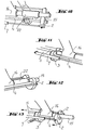
- Figs. 10, 11, 12 and 13 show the logical sequence of operations for inserting a bushing.
- With reference now to Fig. 1, the
device 1 of the present invention comprises two self-centeringforks fork 2 is fixed to therods 4 of twocylinders 5 whilefork 3 is fixedly secured toflanges 6 of saidcylinders 5. - In order to obtain back thrust for returning the device to the inoperative position, two
air cylinders 7 are arranged on either side and are fixed tocylinders 5 and to the slidingfork 2. - The force required for extraction and insertion of the bushings is obtained through a manual
hydraulic pump 8 actuating said device by the pressure obtained by acting on the control lever 9. - With reference now to Figs. 2 and 3, in order to extract the bushing from a support, the two
half sleeves shaft 15. - As the outer diameter of said sleevel is slightly less than the support diameter, it is clear that a particularly precise axial thrust may be effected on the metal part of the bushing to be replaced.
- It is also necessary to use the
gauge blocks - Referring now to Figs. 4 through 9, the various operative stages of the bushing extraction are now illustrated.
- After having removed the
screw propeller 14 from theshaft 15, the device of the present invention is positioned astride thesupport 16 with thesliding fork 2 on the side of the screw connection. - Then the two
sleeve halves gauge block - After having connected the
hose 20 of the manualhydraulic pump 8 to thefitting 21 of the cylinders, when pressure is delivered, thesliding fork 2 through thegauge block support 16 and consequently through thesleeve halves bushing 22 to be replaced is axially pushed until the extraction is complete. - Referring now to Figs. 10 through 13, the various operative stages of the bushing insertion are illustrated.
- After having slipped a
fresh bushing 22 on theshaft 15, the device of the present invention is so positioned that thesliding fork 2 is between said bushing 22 and thesupport 16. - On the
fixed fork 2 the gauge block is positioned, then pressure is delivered to thecylinders 5, the device abuts on thesupport 16 and thesliding fork 3 pushes axially thebushing 22 until it is completely inserted into its seat. - It is therefore apparent that the device of the present invention attains the above mentioned objects and solves in an optimal and practical way the problems relating to the replacement of bushings for driving shafts of screw propellers for boats, and it has to be pointed out that the foregoing detailed description of a preferred embodiment does not limit the scope of the invention, but on the contrary it has to be understood that many modifications, variations, additions or substitutions of elements may be resorted to the parts and structures of the device, without altering however the spirit and the object of the invention or departing from its scope of protection, as it is defined in the appended claims.
Claims (4)
Priority Applications (1)
| Application Number | Priority Date | Filing Date | Title |
|---|---|---|---|
| AT82111383T ATE32989T1 (en) | 1982-08-10 | 1982-12-08 | HYDRAULIC DEVICE FOR PULLING OR INSERTING SHIP BEARING SLEEVE. |
Applications Claiming Priority (2)
| Application Number | Priority Date | Filing Date | Title |
|---|---|---|---|
| IT22793/82A IT1152354B (en) | 1982-08-10 | 1982-08-10 | HYDRAULIC TOOL FOR THE EXTRACTION AND INTRODUCTION OF MARINE BUSHINGS |
| IT2279382 | 1982-08-10 |
Publications (3)
| Publication Number | Publication Date |
|---|---|
| EP0100792A2 true EP0100792A2 (en) | 1984-02-22 |
| EP0100792A3 EP0100792A3 (en) | 1985-05-29 |
| EP0100792B1 EP0100792B1 (en) | 1988-03-16 |
Family
ID=11200498
Family Applications (1)
| Application Number | Title | Priority Date | Filing Date |
|---|---|---|---|
| EP82111383A Expired EP0100792B1 (en) | 1982-08-10 | 1982-12-08 | Hydraulic device for removing and inserting marine bushings |
Country Status (4)
| Country | Link |
|---|---|
| EP (1) | EP0100792B1 (en) |
| AT (1) | ATE32989T1 (en) |
| DE (1) | DE3278235D1 (en) |
| IT (1) | IT1152354B (en) |
Cited By (10)
| Publication number | Priority date | Publication date | Assignee | Title |
|---|---|---|---|---|
| EP0397405A1 (en) * | 1989-05-08 | 1990-11-14 | Posi Lock Puller, Inc. | Hydraulic puller |
| EP0409373A1 (en) * | 1989-07-21 | 1991-01-23 | Keystone International Holdings Corp. | Apparatus for inserting valve seats in valve bodies |
| WO2002079681A2 (en) * | 2001-04-02 | 2002-10-10 | Dts-Pro-Sys Gmbh | Device for pressing in a sealing sleeve |
| EP1616668A1 (en) * | 2004-07-15 | 2006-01-18 | BAE Systems Ltd | Tool for assembling and dismantling valves |
| CN102672667A (en) * | 2012-05-04 | 2012-09-19 | 北京航天动力研究所 | Hydraulic puller of link plate |
| CN103244504A (en) * | 2013-04-27 | 2013-08-14 | 中联重科股份有限公司 | Press-fitting oil cylinder and press-fitting equipment |
| WO2014006304A1 (en) * | 2012-07-03 | 2014-01-09 | Aircelle | Tool for banding mechanical components and banding method using such a tool |
| EP2598280A4 (en) * | 2010-07-30 | 2017-01-25 | Motion Pro. Inc. | Fork seal driver tool |
| CN111673677A (en) * | 2020-07-07 | 2020-09-18 | 湖北清江水电开发有限责任公司 | Device and method for disassembling tight bushing of hydroelectric generating set |
| CN114823006A (en) * | 2022-03-02 | 2022-07-29 | 海洋石油工程股份有限公司 | Be used for sealed retrieval instrument that puts of navel cord cable |
Citations (4)
| Publication number | Priority date | Publication date | Assignee | Title |
|---|---|---|---|---|
| US1591894A (en) * | 1925-07-22 | 1926-07-06 | Daniel H Taylor | Device for positioning packing in stuffing boxes and the like |
| US2669773A (en) * | 1951-04-16 | 1954-02-23 | Tuboscope Company | Means for transferring collars |
| US3432172A (en) * | 1966-11-25 | 1969-03-11 | Allen L Hendrickson | Method and apparatus for installing new packing on a propeller shaft |
| US3638294A (en) * | 1970-01-20 | 1972-02-01 | Walter F Durant | Wheel puller |
-
1982
- 1982-08-10 IT IT22793/82A patent/IT1152354B/en active
- 1982-12-08 EP EP82111383A patent/EP0100792B1/en not_active Expired
- 1982-12-08 DE DE8282111383T patent/DE3278235D1/en not_active Expired
- 1982-12-08 AT AT82111383T patent/ATE32989T1/en not_active IP Right Cessation
Patent Citations (4)
| Publication number | Priority date | Publication date | Assignee | Title |
|---|---|---|---|---|
| US1591894A (en) * | 1925-07-22 | 1926-07-06 | Daniel H Taylor | Device for positioning packing in stuffing boxes and the like |
| US2669773A (en) * | 1951-04-16 | 1954-02-23 | Tuboscope Company | Means for transferring collars |
| US3432172A (en) * | 1966-11-25 | 1969-03-11 | Allen L Hendrickson | Method and apparatus for installing new packing on a propeller shaft |
| US3638294A (en) * | 1970-01-20 | 1972-02-01 | Walter F Durant | Wheel puller |
Cited By (13)
| Publication number | Priority date | Publication date | Assignee | Title |
|---|---|---|---|---|
| EP0397405A1 (en) * | 1989-05-08 | 1990-11-14 | Posi Lock Puller, Inc. | Hydraulic puller |
| EP0409373A1 (en) * | 1989-07-21 | 1991-01-23 | Keystone International Holdings Corp. | Apparatus for inserting valve seats in valve bodies |
| WO2002079681A2 (en) * | 2001-04-02 | 2002-10-10 | Dts-Pro-Sys Gmbh | Device for pressing in a sealing sleeve |
| WO2002079681A3 (en) * | 2001-04-02 | 2003-10-30 | Dts Pro Sys Gmbh | Device for pressing in a sealing sleeve |
| EP1616668A1 (en) * | 2004-07-15 | 2006-01-18 | BAE Systems Ltd | Tool for assembling and dismantling valves |
| EP2598280A4 (en) * | 2010-07-30 | 2017-01-25 | Motion Pro. Inc. | Fork seal driver tool |
| CN102672667A (en) * | 2012-05-04 | 2012-09-19 | 北京航天动力研究所 | Hydraulic puller of link plate |
| WO2014006304A1 (en) * | 2012-07-03 | 2014-01-09 | Aircelle | Tool for banding mechanical components and banding method using such a tool |
| FR2993022A1 (en) * | 2012-07-03 | 2014-01-10 | Aircelle Sa | MECHANICAL PIECE TOOL AND FREQUENCY METHOD USING SUCH TOOL |
| CN103244504A (en) * | 2013-04-27 | 2013-08-14 | 中联重科股份有限公司 | Press-fitting oil cylinder and press-fitting equipment |
| CN111673677A (en) * | 2020-07-07 | 2020-09-18 | 湖北清江水电开发有限责任公司 | Device and method for disassembling tight bushing of hydroelectric generating set |
| CN114823006A (en) * | 2022-03-02 | 2022-07-29 | 海洋石油工程股份有限公司 | Be used for sealed retrieval instrument that puts of navel cord cable |
| CN114823006B (en) * | 2022-03-02 | 2024-03-22 | 海洋石油工程股份有限公司 | Recovery tool for umbilical cable sealing device |
Also Published As
| Publication number | Publication date |
|---|---|
| EP0100792B1 (en) | 1988-03-16 |
| IT1152354B (en) | 1986-12-31 |
| ATE32989T1 (en) | 1988-04-15 |
| EP0100792A3 (en) | 1985-05-29 |
| DE3278235D1 (en) | 1988-04-21 |
| IT8222793A0 (en) | 1982-08-10 |
Similar Documents
| Publication | Publication Date | Title |
|---|---|---|
| EP0100792A2 (en) | Hydraulic device for removing and inserting marine bushings | |
| US3846898A (en) | Puller for bearing carrier | |
| US2631559A (en) | Marine steering device | |
| EP0006278A1 (en) | Breakaway pipe coupling | |
| GB2073085A (en) | Hydraulic pliers for snap rings | |
| US4657449A (en) | Internal sewage line stub cutting tool having automatic bit adjustment | |
| NO160157B (en) | PIPE CONNECTOR. | |
| CN212285889U (en) | Electric spindle and machining center | |
| US4633562A (en) | Arrowhead extractor | |
| EP3269511A1 (en) | Device for gripping diesel engine injectors | |
| CN201309095Y (en) | Automatic core fixing clamp | |
| US3317254A (en) | Demountable marine bearing | |
| CA2544092C (en) | Marine split bearings with right angle removeable grooved retainer covers | |
| US6902452B1 (en) | Marine split bearings with right angle removeable grooved retainer covers | |
| EP0990585A3 (en) | Controllable-pitch propeller, especially for sport boats | |
| DK160472B (en) | PROCEDURE AND APPARATUS FOR PROTECTING THE STRAP SYSTEM FOR A STANDABLE DRIVE SCREW AGAINST FOREIGN BODIES | |
| CA1301561C (en) | Frictional joints | |
| EP1108972A3 (en) | Device for mounting a steering fin on a missile | |
| NO165892B (en) | PROCEDURE AND APPARATUS FOR CONNECTING A STRAINING PIPE TO AN EXISTING PIPE PIPE. | |
| GB2172227A (en) | Hydraulic wedge unit | |
| EP0298675A1 (en) | Sleeve mounting and removal tool | |
| US6939411B2 (en) | Method and tool for cleaning a watercraft speedometer | |
| US3041713A (en) | Puller tool | |
| GB1572926A (en) | Device for stripping off elastic rings lying axially side in annular grooves in the outer periphery of a mould core | |
| WO1995015241A1 (en) | Apparatus and method for installing and removing piston rods |
Legal Events
| Date | Code | Title | Description |
|---|---|---|---|
| PUAI | Public reference made under article 153(3) epc to a published international application that has entered the european phase |
Free format text: ORIGINAL CODE: 0009012 |
|
| AK | Designated contracting states |
Designated state(s): AT BE CH DE FR GB IT LI LU NL SE |
|
| PUAL | Search report despatched |
Free format text: ORIGINAL CODE: 0009013 |
|
| AK | Designated contracting states |
Designated state(s): AT BE CH DE FR GB IT LI LU NL SE |
|
| 17P | Request for examination filed |
Effective date: 19851115 |
|
| 17Q | First examination report despatched |
Effective date: 19860612 |
|
| GRAA | (expected) grant |
Free format text: ORIGINAL CODE: 0009210 |
|
| AK | Designated contracting states |
Kind code of ref document: B1 Designated state(s): AT BE CH DE FR GB IT LI LU NL SE |
|
| PG25 | Lapsed in a contracting state [announced via postgrant information from national office to epo] |
Ref country code: NL Effective date: 19880316 Ref country code: LI Effective date: 19880316 Ref country code: FR Free format text: THE PATENT HAS BEEN ANNULLED BY A DECISION OF A NATIONAL AUTHORITY Effective date: 19880316 Ref country code: CH Effective date: 19880316 Ref country code: BE Effective date: 19880316 Ref country code: AT Effective date: 19880316 |
|
| REF | Corresponds to: |
Ref document number: 32989 Country of ref document: AT Date of ref document: 19880415 Kind code of ref document: T |
|
| ITF | It: translation for a ep patent filed | ||
| PG25 | Lapsed in a contracting state [announced via postgrant information from national office to epo] |
Ref country code: SE Effective date: 19880331 |
|
| REF | Corresponds to: |
Ref document number: 3278235 Country of ref document: DE Date of ref document: 19880421 |
|
| REG | Reference to a national code |
Ref country code: CH Ref legal event code: PL |
|
| EN | Fr: translation not filed | ||
| NLV1 | Nl: lapsed or annulled due to failure to fulfill the requirements of art. 29p and 29m of the patents act | ||
| PG25 | Lapsed in a contracting state [announced via postgrant information from national office to epo] |
Ref country code: GB Effective date: 19881208 |
|
| PG25 | Lapsed in a contracting state [announced via postgrant information from national office to epo] |
Ref country code: LU Free format text: LAPSE BECAUSE OF NON-PAYMENT OF DUE FEES Effective date: 19881231 |
|
| PLBE | No opposition filed within time limit |
Free format text: ORIGINAL CODE: 0009261 |
|
| STAA | Information on the status of an ep patent application or granted ep patent |
Free format text: STATUS: NO OPPOSITION FILED WITHIN TIME LIMIT |
|
| 26N | No opposition filed | ||
| GBPC | Gb: european patent ceased through non-payment of renewal fee | ||
| PG25 | Lapsed in a contracting state [announced via postgrant information from national office to epo] |
Ref country code: DE Effective date: 19890901 |
|
| ITTA | It: last paid annual fee |