EP0100649B1 - Durchflussregler - Google Patents
Durchflussregler Download PDFInfo
- Publication number
- EP0100649B1 EP0100649B1 EP83304344A EP83304344A EP0100649B1 EP 0100649 B1 EP0100649 B1 EP 0100649B1 EP 83304344 A EP83304344 A EP 83304344A EP 83304344 A EP83304344 A EP 83304344A EP 0100649 B1 EP0100649 B1 EP 0100649B1
- Authority
- EP
- European Patent Office
- Prior art keywords
- oxygen
- regulator
- gas
- anaesthesia
- concentration
- Prior art date
- Legal status (The legal status is an assumption and is not a legal conclusion. Google has not performed a legal analysis and makes no representation as to the accuracy of the status listed.)
- Expired
Links
- 239000012530 fluid Substances 0.000 title description 2
- 239000001301 oxygen Substances 0.000 claims description 89
- 229910052760 oxygen Inorganic materials 0.000 claims description 89
- QVGXLLKOCUKJST-UHFFFAOYSA-N atomic oxygen Chemical compound [O] QVGXLLKOCUKJST-UHFFFAOYSA-N 0.000 claims description 88
- 239000007789 gas Substances 0.000 claims description 63
- 206010002091 Anaesthesia Diseases 0.000 claims description 24
- 238000001949 anaesthesia Methods 0.000 claims description 24
- 230000037005 anaesthesia Effects 0.000 claims description 24
- 239000006200 vaporizer Substances 0.000 claims description 12
- 230000003444 anaesthetic effect Effects 0.000 claims description 11
- 238000009423 ventilation Methods 0.000 claims description 7
- 239000000203 mixture Substances 0.000 claims description 6
- 230000002269 spontaneous effect Effects 0.000 claims description 5
- 238000005399 mechanical ventilation Methods 0.000 claims description 4
- 230000004913 activation Effects 0.000 claims 3
- MYMOFIZGZYHOMD-UHFFFAOYSA-N Dioxygen Chemical compound O=O MYMOFIZGZYHOMD-UHFFFAOYSA-N 0.000 claims 1
- 230000003213 activating effect Effects 0.000 claims 1
- 230000009849 deactivation Effects 0.000 claims 1
- 230000001419 dependent effect Effects 0.000 claims 1
- 229910001882 dioxygen Inorganic materials 0.000 claims 1
- 239000003112 inhibitor Substances 0.000 claims 1
- GQPLMRYTRLFLPF-UHFFFAOYSA-N Nitrous Oxide Chemical compound [O-][N+]#N GQPLMRYTRLFLPF-UHFFFAOYSA-N 0.000 description 78
- 239000001272 nitrous oxide Substances 0.000 description 39
- 239000003039 volatile agent Substances 0.000 description 17
- 238000010586 diagram Methods 0.000 description 7
- 238000000034 method Methods 0.000 description 3
- CURLTUGMZLYLDI-UHFFFAOYSA-N Carbon dioxide Chemical compound O=C=O CURLTUGMZLYLDI-UHFFFAOYSA-N 0.000 description 2
- 230000003111 delayed effect Effects 0.000 description 2
- 238000013461 design Methods 0.000 description 2
- 238000006213 oxygenation reaction Methods 0.000 description 2
- 238000011160 research Methods 0.000 description 2
- 230000007704 transition Effects 0.000 description 2
- 238000012935 Averaging Methods 0.000 description 1
- 230000009471 action Effects 0.000 description 1
- 239000002671 adjuvant Substances 0.000 description 1
- 229940124326 anaesthetic agent Drugs 0.000 description 1
- 230000002238 attenuated effect Effects 0.000 description 1
- 229910002092 carbon dioxide Inorganic materials 0.000 description 1
- 239000001569 carbon dioxide Substances 0.000 description 1
- 239000003795 chemical substances by application Substances 0.000 description 1
- 238000010276 construction Methods 0.000 description 1
- 239000012895 dilution Substances 0.000 description 1
- 238000010790 dilution Methods 0.000 description 1
- 230000009977 dual effect Effects 0.000 description 1
- 230000000694 effects Effects 0.000 description 1
- 239000000284 extract Substances 0.000 description 1
- 210000003414 extremity Anatomy 0.000 description 1
- 231100001261 hazardous Toxicity 0.000 description 1
- 230000004941 influx Effects 0.000 description 1
- 238000012986 modification Methods 0.000 description 1
- 230000004048 modification Effects 0.000 description 1
- 239000013643 reference control Substances 0.000 description 1
- 230000004044 response Effects 0.000 description 1
- 230000035945 sensitivity Effects 0.000 description 1
- HUAUNKAZQWMVFY-UHFFFAOYSA-M sodium;oxocalcium;hydroxide Chemical compound [OH-].[Na+].[Ca]=O HUAUNKAZQWMVFY-UHFFFAOYSA-M 0.000 description 1
- 239000000243 solution Substances 0.000 description 1
- 239000000126 substance Substances 0.000 description 1
- 210000003813 thumb Anatomy 0.000 description 1
- 238000012795 verification Methods 0.000 description 1
- 230000000007 visual effect Effects 0.000 description 1
- 239000002699 waste material Substances 0.000 description 1
Images






Classifications
-
- A—HUMAN NECESSITIES
- A61—MEDICAL OR VETERINARY SCIENCE; HYGIENE
- A61M—DEVICES FOR INTRODUCING MEDIA INTO, OR ONTO, THE BODY; DEVICES FOR TRANSDUCING BODY MEDIA OR FOR TAKING MEDIA FROM THE BODY; DEVICES FOR PRODUCING OR ENDING SLEEP OR STUPOR
- A61M16/00—Devices for influencing the respiratory system of patients by gas treatment, e.g. ventilators; Tracheal tubes
- A61M16/10—Preparation of respiratory gases or vapours
- A61M16/104—Preparation of respiratory gases or vapours specially adapted for anaesthetics
-
- A—HUMAN NECESSITIES
- A61—MEDICAL OR VETERINARY SCIENCE; HYGIENE
- A61M—DEVICES FOR INTRODUCING MEDIA INTO, OR ONTO, THE BODY; DEVICES FOR TRANSDUCING BODY MEDIA OR FOR TAKING MEDIA FROM THE BODY; DEVICES FOR PRODUCING OR ENDING SLEEP OR STUPOR
- A61M16/00—Devices for influencing the respiratory system of patients by gas treatment, e.g. ventilators; Tracheal tubes
- A61M16/10—Preparation of respiratory gases or vapours
- A61M16/1005—Preparation of respiratory gases or vapours with O2 features or with parameter measurement
- A61M16/1015—Preparation of respiratory gases or vapours with O2 features or with parameter measurement using a gas flush valve, e.g. oxygen flush valve
-
- G—PHYSICS
- G05—CONTROLLING; REGULATING
- G05D—SYSTEMS FOR CONTROLLING OR REGULATING NON-ELECTRIC VARIABLES
- G05D21/00—Control of chemical or physico-chemical variables, e.g. pH value
- G05D21/02—Control of chemical or physico-chemical variables, e.g. pH value characterised by the use of electric means
-
- A—HUMAN NECESSITIES
- A61—MEDICAL OR VETERINARY SCIENCE; HYGIENE
- A61M—DEVICES FOR INTRODUCING MEDIA INTO, OR ONTO, THE BODY; DEVICES FOR TRANSDUCING BODY MEDIA OR FOR TAKING MEDIA FROM THE BODY; DEVICES FOR PRODUCING OR ENDING SLEEP OR STUPOR
- A61M16/00—Devices for influencing the respiratory system of patients by gas treatment, e.g. ventilators; Tracheal tubes
- A61M16/0051—Devices for influencing the respiratory system of patients by gas treatment, e.g. ventilators; Tracheal tubes with alarm devices
-
- A—HUMAN NECESSITIES
- A61—MEDICAL OR VETERINARY SCIENCE; HYGIENE
- A61M—DEVICES FOR INTRODUCING MEDIA INTO, OR ONTO, THE BODY; DEVICES FOR TRANSDUCING BODY MEDIA OR FOR TAKING MEDIA FROM THE BODY; DEVICES FOR PRODUCING OR ENDING SLEEP OR STUPOR
- A61M16/00—Devices for influencing the respiratory system of patients by gas treatment, e.g. ventilators; Tracheal tubes
- A61M16/0057—Pumps therefor
- A61M16/0075—Bellows-type
-
- A—HUMAN NECESSITIES
- A61—MEDICAL OR VETERINARY SCIENCE; HYGIENE
- A61M—DEVICES FOR INTRODUCING MEDIA INTO, OR ONTO, THE BODY; DEVICES FOR TRANSDUCING BODY MEDIA OR FOR TAKING MEDIA FROM THE BODY; DEVICES FOR PRODUCING OR ENDING SLEEP OR STUPOR
- A61M16/00—Devices for influencing the respiratory system of patients by gas treatment, e.g. ventilators; Tracheal tubes
- A61M16/021—Devices for influencing the respiratory system of patients by gas treatment, e.g. ventilators; Tracheal tubes operated by electrical means
- A61M16/022—Control means therefor
- A61M16/024—Control means therefor including calculation means, e.g. using a processor
Definitions
- the present invention relates to a fluid flow regulator and relates particularly, although not exclusively, to an anaethesia gas flow regulator.
- Anaesthetic gases are usually administered through a "circle". This means that two pipes link the patient with the gas flow regulator, one carrying gas to the patient and the other taking exhaled gas through a soda lime canister which extracts carbon dioxide. Fresh gas is added to the purified gas and the mixture returned to the patient.
- the gas is usually a mixture of oxygen and nitrous oxide.
- the circle has a controlled leak to the atmosphere, the gas from which is conducted out of the operating theatre to avoid pollution.
- an object of the present invention to provide an anaesthetic gas flow regulator which requires minimal supervision and will automatically regulate the oxygen concentration.
- a further object is to provide a gas flow regulator that does not require manually controlled oxygen and nitrous oxide flow meters.
- an anaesthetic gas flow regulator including, a plurality of actuatable valves and circuit means responsive to a plurality of signals for selective actuation of said valves.
- the circuit means allows only one of said valves to be open at any one time.
- the circuit means may be coupled to at least one switching device which affects the actuation cycle of said valves.
- an anaesthetic gas flow regulator control means including, a plurality of electrical outputs for controlling the actuation of valves for flow of oxygen and anaesthesia gas, said control means providing an "oxygen” signal when a predetermined oxygen concentration has been reached and a "volume” signal when oxygen or anaesthesia gas is required, said "oxygen" and “volume” signals being gated to provide an output to one of said valves to cause flow of either oxygen or anaesthesia gas.
- the function of the regulator is to supply nitrous oxide and oxygen to an anaesthetic circle so that when the circuit is totally closed, circuit volume and oxygen concentration are maintained automatically.
- the device works equally well with controlled (I.P.P.V.) or spontaneous ventilation (SV).
- I.P.P.V. controlled
- SV spontaneous ventilation
- Incorporated within the invention but functionally distinct from the regulator is a servo system which controls the concentration of volatile adjuvant (VA) in the circle.
- a standard digital clocking system records the times for which each of three valves has been open. As the flow rates are fixed, total gas flow over any period may be estimated. The clocking system is not described as its use is only for research purposes.
- Gas is supplied by a high flow and a low flow oxygen valve and a high flow and a low flow nitrous oxide valve.
- Logic circuits select which valve is opened and for how long. There are two interreacting logic circuits, volume logic and oxygen concentration logic.
- the control panel is divided into three parts, one for the control of each function-timing (not shown); circuit volume and oxygen concentration; and VA concentration.
- FIG. 3 the front display panel of the regulator is shown.
- the left hand portion of the panel is to do with the digital clocking system.
- the "Reset” button resets all three clocks simultaneously.
- the selector switch selects the display to show the accumulated times of opening for the selected valve.
- the clocks read up to ten hours in hours, minutes and seconds, with an accuracy of ⁇ 0.05 sec.
- the middle part of the panel relates to the regulator itself.
- two LEDs These indicate the function of the SV volume logic.
- the "Bag Fill" button to their right overrides the volume logic so that gas appropriate to an oxygen analyzer reading is delivered to the circuit until the button is released.
- Ventilation Mode switch This selects either I.P.P.V. or SV volume sensors to activate the volume logic.
- the calibrated knob to its right and below the "Bag Fill” button controls a delay in the volume sensing circuit.
- the LEDs indicate which valve is operating with the upper LEDs for the high flow valves and the lower LEDs for low flow valves.
- the switch is the gas "On/Off" switch.
- the left hand panel is for oxygen whereas the right one is for nitrous oxide.
- the left hand one is the "Oxygen Off” alarm which flashes red if the nitrous oxide switch is switched on when oxygen is off, or when oxygen is switched off when nitrous oxide is on. At the same time an audible alarm sounds.
- the right hand LED is marked "Close Pop-Off".
- the right hand panel relates to the VA servo.
- the knob below the left hand end of the meter controls the position of the pointer on the scale. It is marked “Set V.A. Reference”.
- the servo will attempt to maintain a reading on the VA analyzer to match the reading on this scale.
- the switch below the knob is the VA servo mode switch. It is marked “Standby/Run”.
- the servo becomes operational.
- the upper one controls the sensitivity of the meter, from 0.5% full scale deflection in the up position to 5.0% full scale deflection in the down position.
- the servo moves the vaporizer setting in steps.
- the lower switch selects the step size. Neither of these switches need be shifted from the "Up" position in use.
- the volume and concentration logic are integrated so that at all times the concentration logic enables (selects) one set of valves, either oxygen or nitrous oxide.
- concentration logic When the volume logic indicates that volume is required, gas is supplied from the appropriate valve. This controls volume and oxygen concentration simultaneously.
- the VA servo is driven by a comparator which classifies the concentration of VA as either higher, equal to or lower than the VA reference. If it is higher, the servo shifts the vaporizer control "down". If it is lower, the control is shifted "up”. If they are equal, no action is taken.
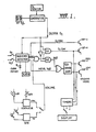
- FIG 1 shows a functional schematic diagram of the regulator where the critical components are gates G1 and G2. These gates have two inputs, Volume and Concentration (Deliver Oxygen).
- the system works such that if volume needs replenishing, either oxygen or nitrous oxide will be delivered depending on the logic level of the "Deliver Oxygen" line.
- the operator sets the percentage of oxygen he wishes to maintain on the front panel BCD thumbwheel switch (See Figure 3).
- a conventional electronic-oxygen analyzer measures the actual oxygen concentration. These two values are compared to drive the "Deliver Oxygen" line.
- the "Volume” line is derived from one of two possible sources.
- S.V. spontaneous ventilation
- I.P.P.V. mechanical ventilation
- I.P.P.V. an LDR (light dependant resistor) determines when the bellows is full.
- a rate control is provided to ensure that gas is delivered only during the post expiration pause.
- the front panel switch I.P.P.V./S.V. selects the appropriate logic for the ventilation method being used.
- Front panel switches are provided for oxygen and nitrous oxide On/Off.
- the switches are connected to a sequence detector which ensures that switch settings are hazardous to the patient are ignored by the control logic. In these cases the alarm, audible and visual, will be turned on.
- the main output from the sequence detector is the "volume enable" line.
- Also provided is the drive for the high flow oxygen valve for pre-oxygenation, and drive for the initial delivery of nitrous oxide.
- the "Close Pop-Off" LED indicates to the operator when the circle should be closed.
- Gate G1 drives the low flow oxygen valve whereas G2 drives a timing circuit.
- the timing circuit changes flow from nitrous oxide High to nitrous oxide Low when correct flow rates can no longer be maintained with the high flow nitrous oxide valve.
- timers Not fundamental to the system, but provided for research purposes are three timers. They monitor the On times of the high and low flow nitrous oxide valves and the low flow oxygen valve. They display an accumulated total time for the flow of each valve on a common display.
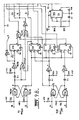
- FIG. 2 The interconnection of the nitrous oxide and oxygen gases is shown in Figure 2..
- This figure shows the four solenoid valves shown in Figure 1 and the manner in which they are coupled together so that at any one time only one valve will be opened.
- an override valve labelled "Emergency Push" is provided to allow oxygen to be supplied at all times, irrespective of the solenoid valve actuated.
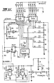
- FIG 4 shows a functional schematic diagram for such volatile agent control which is independent of the gas flow control.
- the volatile agent monitor or EMMA is connected to a voltage controlled oscillator (V.C.O.).
- V.C.O. voltage controlled oscillator
- Connected to another V.C.O. is a front panel "Set V.A. Reference” (See Figure 3). This setting is indicated on an analogue meter movement 10.
- the frequency output of each V.C.O. is dependant on the voltage at its input. If the two input voltages are equal, then the output frequencies will also be equal.
- the output of each V.C.O. is connected to two 14 bit binary counters which count up for 20 seconds. At the end of this time the counter outputs are compared.
- the outputs of the comparator are connected to a 6 bit up-down counter configured as a digital to analogue converter.
- the converter output is applied to a pulse generator circuit which in turn drives the motor connected to the vaporizer concentration control.
- the clock to the D to A converter is inhibited.
- the analogue output voltage remains unchanged as does the position of the vaporizer control. If the monitor reading is greater than the reference count, the D to A converter decrements and the analog output reduces, the control then closes one step. If on the other hand the monitor reads less than the reference, the control opens one step. In this way, the concentration of volatile agent is maintained.
- An electronics cabinet contains the three plug-in circuit boards, one each for Gas Control ( Figures 9A to, 9D), Volatile Agent Control ( Figures 10A to 10C) and Timing (not shown).
- the boards are housed in a semi-enclosed card frame.
- Also contained in the cabinet are two Power-One D.C. power supplies one 5v and one 12v shown in Figure 14. All the controls are mounted on the front panel and all the input-output connectors on the rear panel.
- the rear panel also houses the solenoid drive transistors and the 2.5v regulator. This regulator supplies power to the globes mounted in the ventilator and on a bag cradle.
- the gas control board shown in Figures 9A to 9D can be divided into four sections, namely: oxygen analyzer, volume analyzer, sequence detector and nitrous oxide change-over. These sections will be described in turn.
- This circuit runs at 5v and is interfaced to the rest of the controller by transistor Q5 powered at 12v.
- Two inputs are provided by the conventional electronic oxygen analyzer. They are labelled Oxygen Clock and Oxygen Reset. They are applied to Z12, a 74C901 CMOS to CMOS buffer.
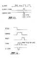
- the clock pulses are counted by Z13 and Z14 decade counters whose outputs are sampled at Oxygen Reset time by Z15 and Z16 (D flip flops). Only the measured oxygen concentration is available at the output of the flip flops.
- the oxygen reset pulse is delayed to provide a counter reset which zeros the counters to enable the next pulse train to be computed. This timing is shown in Figure 15.
- the outputs of the D flip flops are applied to Z17 and Z18 forming an 8 bit binary magnitude comparator. Also applied to the comparator are the outputs of a two decade BCD thumbwheel switch mounted on the front display panel ( Figure 3). Here the operator sets the desired oxygen concentration.
- the A>B output of the comparator is inverted and buffered by transistor Q5 to provide the "Deliver Oxygen" output to the other sections. A high level is present at this output if the measured percentage of oxygen is too low.
- This circuit provides one output, "Volume”. Selection is made on the front panel for S.V. or I.P.P.V.
- two phototransistors a1 and Q2 drive Z1, 74C00 NAND gates.
- Q1 and Q2 are mounted on the frame 12, with Q1 above Q2.
- Reference to Figures 5 and 6 illustrates a rebreathing bag 14 sitting within frame 12 having a base 18, end walls 20 and 22 and support members 24 and 26.
- Phototransistors Q1 and Q2 are adjustable along support member 24 whilst corresponding globes B1 and B2 are adjustable along support member 26. For pin 6 of Z1 to go high both Q1 and Q2 must be on. This level remains high until both phototransistors are off.
- the bag must deflate past Q2. It remains high until the bag is inflated past Q1.
- the positions of Q1 and Q2 are adjustable on support member 24 to cater for different tidal volumes.
- Transistors Q3 and Q4 drive front panel LEDs across the phototransistors Q1 and Q2 to allow easy verification of the adjustment of the phototransistors and their respective globes on their support members.
- a light dependant resistor mounted in the ventilator controls the volume.
- LDR light dependant resistor
- a signal is required to indicate that inspiration has begun. The means of arranging this depends on the design of the ventilator.
- Reference to Figures 7 and 8 shows the ventilator operates by compressing a bellows 30 whose base 32 moves upwardly during inspiration and downwardly during expiration where the downward movement is the phase in which the bellows is refilled.
- a light beam is directed horizontally across a diameter of the bellows but just below it by globe B3.
- the beam is directed onto LDR 34 mounted on ring 36.
- a small projection 38 interrupts the beam just before the bellows reaches the end of its downward travel.
- the LDR 34 drives a 74C14 Schmitt Trigger whose output is taken to Z19 and Z20, a JK flip flop and a 555 Timer respectively.
- the time out of the 555 is adjustable by the front panel control marked "Rate" ( Figure 3). This delay is adjustable from 0 to 10 seconds. If LDR 34 is still lit after the delay time, the Q output of the flip flop goes high, calling for Volume. The delay ensures that gas will only be delivered during the post expiration pause. This prevents overflow due to exhalation after the bellows have been filled.
- Two front panel switches are provided to control the operation of the solenoid valves. They are Oxygen On/Off and Nitrous Oxide On/Off. Z21 and Z22, with associated gates, ensure that switch settings which may endanger the patient are locked out.
- the circuit has two alarm outputs which enable a flashing LED and a sonor alarm.
- Table 1 shows the logic levels at various points on the circuit for all switch settings. It should be noted that the outputs are a function of the present switch setting and the previous switch setting. It should also be noted that an alarm condition exists whenever nitrous oxide is selected without oxygen also being selected.
- Line 1 of the table shows the condition when both switches are off. It also shows that the four solenoid valves are off. This can be considered as the start condition. Oxygen is now switched On for pre-oxygenation. This brings the high flow oxygen valve On.
- nitrous oxide is switched On. This switches the Oxygen High valve Off and enables the nitrous oxide valves. (Nitrous Oxide High comes On as described in the nitrous oxide change-over section description). When the concentration of oxygen comes down to the preset level, line 4 is reached. The volume output is enabled via Z6 (pin 8). This is normal running mode.
- Table 2 shows the circuit response for the two alarm conditions.
- the first line shows what happens if, from the start condition, the nitrous oxide switch is operated first.
- the alarm output is enabled but all valves remain off.
- the alarm is cleared when the nitrous oxide switch is turned off.
- the second line shows what happens if, from normal operation (Table 1, line 4), the oxygen switch is turned off. The alarm is enabled but the normal operation of the valves continues. The alarm is cleared by turning the oxygen switch on again.
- a 555 bistable multivibrator Z11 provides 10 msecs clock pulses to a 74C90 decade counter 210 and this provides a clock pulse to pin 12 of Z9 at 100 msec provided the counter is enabled. The counter is enabled at pins 2 and 3 whenever the high flow nitrous oxide valve is On. A delayed pulse is also derived from this level which is applied to the clear input of Z9 (pin 13).
- the volatile agent control board shown in Figures 10A to 10C will now be described.
- the conventional Engstrom EMMA volatile agent monitor monitors the percentage of volatile agents in the range 0 to 5%.
- the recorder output is taken from EMMA and applied to pin 25 and 23 of the board connector.
- the 1N% output from EMMA is attenuated by 2 and level shifted to a 3V reference by the 741 op-amp.
- the output of the 741 is applied to the VCO input of a 4046 Phase Lock Loop (PLL).
- PLL Phase Lock Loop
- the level shift is necessary to come within the linear portion of the VCO.
- the circuit responds to 0 to 4% volatile agent.
- the VCO runs from about 110 to 350 Hz.
- a IK multiturn trimpot is provided to trim this range.
- the VCO provides the clock input to a 4020 14 stage binary counter.
- the reference control feeds the reference meter circuit and another 4046 PLL.
- the meter has two ranges, 0 to 0.5% and 0 to 5%.
- the 4046 is configured exactly the same as to 4046 in the measure circuit and is shown in Figure 11. It also feeds a 4020 counter.
- Eight outputs, b6 to b13, are taken from the counters and feed two 74C85 chips configured as an 8 bit magnitude comparator.
- the resulting A>B signal is applied to the up/down control line of two 4029 up/down binary counters.
- these counters form a 6 bit digital to analogue converter.
- Also coupled to this counter is an 8 bit dip switch to the jam inputs. This allows a predetermined value to be present in the counter. This number is entered into the counter whenever the "standby/run" switch is put into the Run position.
- the A>B signal is fed also to half of a 74C107 flip flop configured as a D flip flop, whose outputs feed a 74C151 eight channel digital multiplexer.
- the operation of the multiplexer will be explained later.
- the output of the D to A converter is buffered by an MPF102 JFET and fed to a 555 timer connected as a variable pulse width monostable. Also feeding the monostable is the output of a 555 astable with a pulse repetition rate of about 20 msec.
- the resultant pulse train from the monostable directly drives a model aeroplane servo motor which is mechanically coupled to the vaporizer.
- the position of the servo is related to the pulse width and the PRR is not critical.
- the vaporizer used in this embodiment is a modified "Goldman" vaporizer.
- Standby/Run switch Part of the Standby/Run switch is connected at the MPF102 and to a voltage divider. In the standby position the output of the D to A converter is disconnected and a bias voltage is applied to the gate. This voltage holds the vaporizer in the closed position.
- a 555 timer and a 74C90 decade counter provide basic timing at a 20 second rate. This timing is not critical but is selected to be greater than at least two breath times. This is necessary to overcome small fuctuations in the monitor during inspiration and expiration.
- All other timing is derived from the 20 Sec. signal by 74C221 dual monostables.
- One provides Compare and Reset pulses.
- the Compare pulse is applied to the outputs of the comparator.
- the 4020 counters feed the comparator. These are fed from the VCOs and hence represent the average, over 20 seconds of the reference and measure inputs. The outputs of the comparator are therefore only considered valid during Compare time. After this the counters are reset.
- D Clock which gates the A>B level into the D flip flop connected to the 74C151 multiplexer.
- the other is the clock pulse to the D to A converter. This can in fact be two pulses, determined by the Step Size Switch. For large steps of the servo the D to A increments or decrements twice.
- the comparator determines whether the concentration of volatile agent is correct, high or low. This sets up the D to A converter which already holds some count. (This may have just been entered via the jam inputs). If the concentration is OK the counter remains as it is. If A:AB the clock pulse(s) is gated to the counters which increment or decrement. This changes the voltage to the monostable which changes its pulse width. Hence the servo will move to adjust the concentration. Use of a large step size of the servo allows the reference point to be reached quickly, however, the servo tends to hunt around the reference point. The circuit should maintain the concentration to within 0.05 vol.% and using small step size very little hunting occurs.
- the purpose of the 74C151 multiplexer is to determine whether the servo is at an extreme end of its travel. If it is, the counter is inhibited from counting. This ensures that the counter does not "wrap-around".
- the servo is full open and the counter is near its maximum count. This situation can occur when the operation has started and the uptake of the volatile agent by the body is rapid.
- the comparator is still calling for more agent so the counter gets to its maximum count.
- One more clock pulse causes the counter to count past maximum to zero.
- the servo now goes fully closed and the volatile agent is cut off.
- the reverse situation can occur in the down count direction and is potentially more dangerous.
- the multiplexer samples the counter output and applies a high logic level to the carry-in input of the first counter when the. servo is in its maximum or minimum position. This inhibits the count.
Landscapes
- Health & Medical Sciences (AREA)
- Engineering & Computer Science (AREA)
- Emergency Medicine (AREA)
- General Health & Medical Sciences (AREA)
- Veterinary Medicine (AREA)
- Biomedical Technology (AREA)
- Heart & Thoracic Surgery (AREA)
- Hematology (AREA)
- Life Sciences & Earth Sciences (AREA)
- Animal Behavior & Ethology (AREA)
- Pulmonology (AREA)
- Public Health (AREA)
- Anesthesiology (AREA)
- Physics & Mathematics (AREA)
- General Physics & Mathematics (AREA)
- Automation & Control Theory (AREA)
- Respiratory Apparatuses And Protective Means (AREA)
- Investigating Or Analyzing Materials By The Use Of Electric Means (AREA)
- Feedback Control In General (AREA)
- Flow Control (AREA)
- Control Of Non-Electrical Variables (AREA)
Claims (12)
Applications Claiming Priority (2)
| Application Number | Priority Date | Filing Date | Title |
|---|---|---|---|
| AUPF514682 | 1982-07-30 | ||
| AU5146/82 | 1982-07-30 |
Publications (3)
| Publication Number | Publication Date |
|---|---|
| EP0100649A2 EP0100649A2 (de) | 1984-02-15 |
| EP0100649A3 EP0100649A3 (en) | 1984-08-22 |
| EP0100649B1 true EP0100649B1 (de) | 1989-01-18 |
Family
ID=3769655
Family Applications (1)
| Application Number | Title | Priority Date | Filing Date |
|---|---|---|---|
| EP83304344A Expired EP0100649B1 (de) | 1982-07-30 | 1983-07-27 | Durchflussregler |
Country Status (4)
| Country | Link |
|---|---|
| US (1) | US4651729A (de) |
| EP (1) | EP0100649B1 (de) |
| JP (1) | JPS5990565A (de) |
| DE (1) | DE3378999D1 (de) |
Families Citing this family (26)
| Publication number | Priority date | Publication date | Assignee | Title |
|---|---|---|---|---|
| SE8700977D0 (sv) * | 1987-03-09 | 1987-03-09 | Olof Werner | Enhet som i olika grad separerar gasinnehallet i drivkrets och mottagarkrets, men som enda tillater gasgenomslepp i bada riktningarna (oppen separation) |
| DE3712598A1 (de) * | 1987-04-14 | 1988-10-27 | Siemens Ag | Inhalations-anaesthesiegeraet |
| US4986268A (en) * | 1988-04-06 | 1991-01-22 | Tehrani Fleur T | Method and apparatus for controlling an artificial respirator |
| US5094235A (en) * | 1989-05-10 | 1992-03-10 | Dragerwerk Aktiengesellschaft | Anesthesia ventilating apparatus having a breathing circuit and control loops for anesthetic gas components |
| US5299568A (en) * | 1989-06-22 | 1994-04-05 | Puritan-Bennett Corporation | Method for controlling mixing and delivery of respiratory gas |
| US5320093A (en) * | 1990-12-21 | 1994-06-14 | Brigham And Women's Hospital | Rapid anesthesia emergence system using closed-loop PCO2 control |
| JP2967731B2 (ja) * | 1996-08-09 | 1999-10-25 | 日本電気株式会社 | D/aコンバータ |
| FR2755260B1 (fr) * | 1996-10-31 | 1998-12-18 | Air Liquide | Procede et installation de regulation de la composition de l'atmosphere d'une enceinte |
| ES2139540B1 (es) * | 1998-04-14 | 2000-09-01 | Mas Marfany Jaime | Metodo de control automatico para el aporte de anestesico a un circuito cerrado a bajos flujos. |
| FI982652A7 (fi) | 1998-12-08 | 2000-06-09 | Instrumentarium Oyj | Sovitelma potilaan hoitotyössä käytettävän laitteiston yhteydessä |
| FI110065B (fi) * | 1998-12-08 | 2002-11-29 | Instrumentarium Oyj | Sovitelma takaisinkytketyn säätöjärjestelmän yhteydessä |
| DE10041007C1 (de) * | 2000-08-22 | 2001-09-13 | Draeger Medizintech Gmbh | Verfahren zur Steuerung eines Beatmungsgeräts |
| AU9320301A (en) * | 2000-09-28 | 2002-04-08 | Invacare Corp | Carbon dioxide-based bi-level cpap control |
| FR2850874B1 (fr) * | 2003-02-07 | 2005-10-07 | Frederic Philippart | Installation de delivrance de melange gazeux |
| US6988509B2 (en) * | 2003-03-17 | 2006-01-24 | Carleton Technologies, Inc. | Riser line shutoff valve |
| US7152598B2 (en) | 2003-06-23 | 2006-12-26 | Invacare Corporation | System and method for providing a breathing gas |
| US7621270B2 (en) | 2003-06-23 | 2009-11-24 | Invacare Corp. | System and method for providing a breathing gas |
| US20080060647A1 (en) * | 2006-09-12 | 2008-03-13 | Invacare Corporation | System and method for delivering a breathing gas |
| US20080202523A1 (en) * | 2007-02-23 | 2008-08-28 | General Electric Company | Setting mandatory mechanical ventilation parameters based on patient physiology |
| US20080230062A1 (en) * | 2007-03-23 | 2008-09-25 | General Electric Company | Setting expiratory time in mandatory mechanical ventilation based on a deviation from a stable condition of exhaled gas volumes |
| WO2009026582A1 (en) | 2007-08-23 | 2009-02-26 | Invacare Corporation | Method and apparatus for adjusting desired pressure in positive airway pressure devices |
| US8434479B2 (en) * | 2009-02-27 | 2013-05-07 | Covidien Lp | Flow rate compensation for transient thermal response of hot-wire anemometers |
| US9089657B2 (en) | 2011-10-31 | 2015-07-28 | Covidien Lp | Methods and systems for gating user initiated increases in oxygen concentration during ventilation |
| EP3242703B1 (de) * | 2015-02-18 | 2025-12-24 | Fisher & Paykel Healthcare Limited | Strömungstherapiesystem |
| EP3088032A1 (de) | 2015-04-27 | 2016-11-02 | Baldus Medizintechnik GmbH | Lachgasmischer zur erzeugung eines lachgasgemisches |
| CN112730606B (zh) * | 2020-12-31 | 2022-09-27 | 青岛精安医疗科技有限责任公司 | 基于压力检测的超声波氧浓度测量方法、系统和制氧系统 |
Citations (2)
| Publication number | Priority date | Publication date | Assignee | Title |
|---|---|---|---|---|
| US3465753A (en) * | 1966-02-18 | 1969-09-09 | Milab Inc | Gas analyzer-controller equipment |
| US3566865A (en) * | 1968-06-12 | 1971-03-02 | Air Reduction | Anesthesia system |
Family Cites Families (12)
| Publication number | Priority date | Publication date | Assignee | Title |
|---|---|---|---|---|
| US2323675A (en) * | 1937-09-18 | 1943-07-06 | Bendix Aviat Corp | Method and means for determining and regulating the mass of a component gas per unit volume of a gaseous mixture |
| US3923056A (en) * | 1974-06-19 | 1975-12-02 | Gen Electric | Compliance compensation for electronically controlled volume respirator systems |
| US4015617A (en) * | 1975-03-25 | 1977-04-05 | Fraser Sweatman, Inc. | Analgesic apparatus |
| NL7707259A (nl) * | 1977-06-30 | 1979-01-03 | Philips Nv | Beademingstoestel. |
| ES231608U (es) * | 1977-10-26 | 1977-12-16 | Manufacturas Medicas, S. A. | Mezclador por control de tiempo. |
| US4150670A (en) * | 1977-11-14 | 1979-04-24 | University Patents, Inc. | Anesthesia detector and display apparatus |
| US4215409A (en) * | 1978-03-13 | 1980-07-29 | Mckesson Company | Flow control system for anesthesia apparatus |
| IT1096151B (it) * | 1978-03-16 | 1985-08-17 | Savelli Aulo | Respiratore artificiale automatico,in particolare per sale di rianimazione e per anestesia |
| US4284103A (en) * | 1978-05-08 | 1981-08-18 | Pemberton J C | Random access valve |
| JPS55166163A (en) * | 1979-06-13 | 1980-12-25 | Citizen Watch Co Ltd | Controller for anesthetic gas |
| US4340044A (en) * | 1980-03-20 | 1982-07-20 | Berkshire Research Partners | Volume ventilator |
| US4328823A (en) * | 1980-05-14 | 1982-05-11 | N.A.D. Inc. | Oxygen flow ratio controller for anesthesia apparatus |
-
1983
- 1983-07-27 EP EP83304344A patent/EP0100649B1/de not_active Expired
- 1983-07-27 DE DE8383304344T patent/DE3378999D1/de not_active Expired
- 1983-07-29 JP JP58137875A patent/JPS5990565A/ja active Pending
-
1985
- 1985-11-15 US US06/798,152 patent/US4651729A/en not_active Expired - Fee Related
Patent Citations (2)
| Publication number | Priority date | Publication date | Assignee | Title |
|---|---|---|---|---|
| US3465753A (en) * | 1966-02-18 | 1969-09-09 | Milab Inc | Gas analyzer-controller equipment |
| US3566865A (en) * | 1968-06-12 | 1971-03-02 | Air Reduction | Anesthesia system |
Non-Patent Citations (3)
| Title |
|---|
| Coles et al., "Computer Control of Respiration and Anaesthesia Medical and Biological Engr., (May 1973), pp. 262-267 * |
| IEEE Transactions on Biomedical Engr., vol. BME-24, no. 4, (Jul. 1977), pp. 331-337 * |
| Westenskow et al., "Instrumentation for measuring continuous oxygen consumption of surgical patients" * |
Also Published As
| Publication number | Publication date |
|---|---|
| DE3378999D1 (en) | 1989-02-23 |
| EP0100649A2 (de) | 1984-02-15 |
| JPS5990565A (ja) | 1984-05-25 |
| EP0100649A3 (en) | 1984-08-22 |
| US4651729A (en) | 1987-03-24 |
Similar Documents
| Publication | Publication Date | Title |
|---|---|---|
| US4651729A (en) | Fluid flow regulator | |
| US4163450A (en) | Method and apparatus for weaning patient from continuous mechanical ventilation | |
| US4281651A (en) | Lung ventilator | |
| US4060078A (en) | Ventilator and method | |
| US4776333A (en) | Ventilator with variable flow pattern | |
| US4380233A (en) | Control device for an artificial respirator | |
| US7347207B2 (en) | Anesthesia apparatus with remote control during operation in a manual ventilation mode | |
| CA2133516C (en) | Nitric oxide delivery system | |
| EP0050125B1 (de) | Konstantvolumenbeatmungsgerät | |
| CA1068610A (en) | Positive pressure ventilator | |
| US4753245A (en) | Apparatus for measuring the oxygen uptake of a person | |
| US5678537A (en) | Oxygen flush for anesthesia systems | |
| US5732693A (en) | Pause control of nitric oxide therapy | |
| GB1338226A (en) | Lung ventilators | |
| US4020834A (en) | Respirator and method | |
| US5931162A (en) | Ventilator which allows spontaneous inhalation and expiration within a controlled breathing mode | |
| JP2000513618A (ja) | 呼吸装置のための特殊ガス投与量供給装置 | |
| JPH0838605A (ja) | 麻酔装置 | |
| ATE452675T1 (de) | Automatische kontrollvorrichtung für die zugabe eines anästethikums an einen geschlossenen kreislauf mit geringer strömung | |
| HUE029106T2 (en) | System for administering medical gas to a patient | |
| IE950831A1 (en) | Ventilator with an input and output unit | |
| DE3537507A1 (de) | Inhalationsbeatmungsgeraet zur aerosol - therapie von patienten | |
| US5619986A (en) | Method and apparatus for controlling the concentration of at least one component in a gas mixture in an anaesthetic system | |
| JPH0390164A (ja) | 患者の呼吸流量に合わせて回路内流量と回路内圧を制御する人工呼吸器 | |
| US3156238A (en) | Device for aiding in the administration of gaseous anesthetic agents |
Legal Events
| Date | Code | Title | Description |
|---|---|---|---|
| PUAI | Public reference made under article 153(3) epc to a published international application that has entered the european phase |
Free format text: ORIGINAL CODE: 0009012 |
|
| AK | Designated contracting states |
Designated state(s): DE GB SE |
|
| PUAL | Search report despatched |
Free format text: ORIGINAL CODE: 0009013 |
|
| AK | Designated contracting states |
Designated state(s): DE GB SE |
|
| 17P | Request for examination filed |
Effective date: 19850131 |
|
| 17Q | First examination report despatched |
Effective date: 19861217 |
|
| GRAA | (expected) grant |
Free format text: ORIGINAL CODE: 0009210 |
|
| AK | Designated contracting states |
Kind code of ref document: B1 Designated state(s): DE GB SE |
|
| REF | Corresponds to: |
Ref document number: 3378999 Country of ref document: DE Date of ref document: 19890223 |
|
| PLBE | No opposition filed within time limit |
Free format text: ORIGINAL CODE: 0009261 |
|
| STAA | Information on the status of an ep patent application or granted ep patent |
Free format text: STATUS: NO OPPOSITION FILED WITHIN TIME LIMIT |
|
| 26N | No opposition filed | ||
| PGFP | Annual fee paid to national office [announced via postgrant information from national office to epo] |
Ref country code: GB Payment date: 19920727 Year of fee payment: 10 |
|
| PGFP | Annual fee paid to national office [announced via postgrant information from national office to epo] |
Ref country code: SE Payment date: 19920729 Year of fee payment: 10 |
|
| PGFP | Annual fee paid to national office [announced via postgrant information from national office to epo] |
Ref country code: DE Payment date: 19920805 Year of fee payment: 10 |
|
| PG25 | Lapsed in a contracting state [announced via postgrant information from national office to epo] |
Ref country code: GB Effective date: 19930727 |
|
| PG25 | Lapsed in a contracting state [announced via postgrant information from national office to epo] |
Ref country code: SE Effective date: 19930728 |
|
| GBPC | Gb: european patent ceased through non-payment of renewal fee |
Effective date: 19930727 |
|
| PG25 | Lapsed in a contracting state [announced via postgrant information from national office to epo] |
Ref country code: DE Effective date: 19940401 |
|
| EUG | Se: european patent has lapsed |
Ref document number: 83304344.1 Effective date: 19940210 |