EP0100583A2 - A compensating cable for an elevator or the like - Google Patents
A compensating cable for an elevator or the like Download PDFInfo
- Publication number
- EP0100583A2 EP0100583A2 EP83302700A EP83302700A EP0100583A2 EP 0100583 A2 EP0100583 A2 EP 0100583A2 EP 83302700 A EP83302700 A EP 83302700A EP 83302700 A EP83302700 A EP 83302700A EP 0100583 A2 EP0100583 A2 EP 0100583A2
- Authority
- EP
- European Patent Office
- Prior art keywords
- cable
- further characterised
- sheath
- volume
- strength member
- Prior art date
- Legal status (The legal status is an assumption and is not a legal conclusion. Google has not performed a legal analysis and makes no representation as to the accuracy of the status listed.)
- Granted
Links
Images


Classifications
-
- H—ELECTRICITY
- H01—ELECTRIC ELEMENTS
- H01B—CABLES; CONDUCTORS; INSULATORS; SELECTION OF MATERIALS FOR THEIR CONDUCTIVE, INSULATING OR DIELECTRIC PROPERTIES
- H01B7/00—Insulated conductors or cables characterised by their form
- H01B7/08—Flat or ribbon cables
- H01B7/0823—Parallel wires, incorporated in a flat insulating profile
-
- B—PERFORMING OPERATIONS; TRANSPORTING
- B66—HOISTING; LIFTING; HAULING
- B66B—ELEVATORS; ESCALATORS OR MOVING WALKWAYS
- B66B7/00—Other common features of elevators
- B66B7/06—Arrangements of ropes or cables
- B66B7/068—Cable weight compensating devices
-
- D—TEXTILES; PAPER
- D07—ROPES; CABLES OTHER THAN ELECTRIC
- D07B—ROPES OR CABLES IN GENERAL
- D07B1/00—Constructional features of ropes or cables
- D07B1/16—Ropes or cables with an enveloping sheathing or inlays of rubber or plastics
- D07B1/162—Ropes or cables with an enveloping sheathing or inlays of rubber or plastics characterised by a plastic or rubber enveloping sheathing
-
- D—TEXTILES; PAPER
- D07—ROPES; CABLES OTHER THAN ELECTRIC
- D07B—ROPES OR CABLES IN GENERAL
- D07B1/00—Constructional features of ropes or cables
- D07B1/16—Ropes or cables with an enveloping sheathing or inlays of rubber or plastics
- D07B1/165—Ropes or cables with an enveloping sheathing or inlays of rubber or plastics characterised by a plastic or rubber inlay
-
- H—ELECTRICITY
- H01—ELECTRIC ELEMENTS
- H01B—CABLES; CONDUCTORS; INSULATORS; SELECTION OF MATERIALS FOR THEIR CONDUCTIVE, INSULATING OR DIELECTRIC PROPERTIES
- H01B7/00—Insulated conductors or cables characterised by their form
- H01B7/0054—Cables with incorporated electric resistances
-
- H—ELECTRICITY
- H01—ELECTRIC ELEMENTS
- H01B—CABLES; CONDUCTORS; INSULATORS; SELECTION OF MATERIALS FOR THEIR CONDUCTIVE, INSULATING OR DIELECTRIC PROPERTIES
- H01B7/00—Insulated conductors or cables characterised by their form
- H01B7/04—Flexible cables, conductors, or cords, e.g. trailing cables
-
- D—TEXTILES; PAPER
- D07—ROPES; CABLES OTHER THAN ELECTRIC
- D07B—ROPES OR CABLES IN GENERAL
- D07B1/00—Constructional features of ropes or cables
- D07B1/22—Flat or flat-sided ropes; Sets of ropes consisting of a series of parallel ropes
-
- D—TEXTILES; PAPER
- D07—ROPES; CABLES OTHER THAN ELECTRIC
- D07B—ROPES OR CABLES IN GENERAL
- D07B2201/00—Ropes or cables
- D07B2201/20—Rope or cable components
- D07B2201/2075—Fillers
- D07B2201/2082—Fillers characterised by the materials used
-
- D—TEXTILES; PAPER
- D07—ROPES; CABLES OTHER THAN ELECTRIC
- D07B—ROPES OR CABLES IN GENERAL
- D07B2501/00—Application field
- D07B2501/20—Application field related to ropes or cables
- D07B2501/2007—Elevators
Definitions
- a prime function of the compensating cable is to provide dynamic weight counterbalance to the weight of the hoist rope(s) as the car goes up and down in the elevator shaft so that the car is dynamically balanced.
- the aggregate weight of the hoist rope and travelling cable should be essentially equal to the weight of the compensating cable at any given position of the car in the elevator shaft.
- the length of the hoist rope between the car and sheave should be equal to the length of the compensating cable between the counterweight and the lowest portion of the compensating cable or, stated alternatively, the length of the hoist rope from car to counterweight is essentially equal to the length of the compensating cable from car to counterweight.
- Prior art compensating cables usually were nothing more than a link chain. Constant raising and lowering of the elevator car caused such chain also to be raised and lowered, rubbing one link against the other causing noise and abrasion.
- Link chains when hung free in an elevator shaft have tendency to form a "point" and not a loop, i.e., the side legs of the chain tend to converge on a single link and form a point at the terminus of the "loop" formed by the chain.
- noise and abrasion result. More often than not, chain type compensating cable would bang into the sidewalls of the elevator shaft and cause damage and additional noise.
- the present invention does not just reduce noise and abrasion, it virtually eliminates them as well as the need for a sash cord.
- the disclosed compensating cable has a higher weight per linear length, is smaller for a given weight per linear length, and has less lateral cable sway, i.e., it is less likely to bang into the sidewalls of the elevator shaft.
- a compensating cable for an elevator or the like comprises an elongated strength member disposed in an elongated sheath, the volume of the sheath not otherwise occupied by the elongated strength member being substantially occupied by a mixture of metal particles and plastics material.
- a compensating cable in accordance with the present invention is far stiffer, inherently forms a free hanging loop between the car and counterweight whose legs are spaced apart, is noiseless and has an ease of travel unknown to the prior art.
- the cable is flat with a plurality of spaced apart strength members each with their longitudinal axis arranged in a line and substantially coplanar with one another and the sheath is a jacket of flexible material containing a plurality of elongated spaced apart cavities therein, the longitudinal axes of the cavities being arranged in a line and substantially coplanar with one another; each cavity containing at least one strength member and the volume of the cavities, not otherwise occupied by the strength member or members, is substantially occupied by the metal and plastics mixture.
- the compensating cable 2 is connected to the bottom of car 8 and to the bottom of counterweight 4. Sometimes, but not always, the compensating cable may be traversed over compensating sheave 6 or it may hang free in a loop like control cable 10. (See element 15 in dotted line).
- the length of compensating chain 2 should be essentially the same length as hoist rope 1, i.e., from car 8 over sheaves 3 to counterweight 9 (excluding wrap around portion around the sheave(s) if any).
- Hoist rope 1 is connected to the roof of car 8, traversed over sheave 3 and connected to the top of counterweight 4.
- hoist ropes there may be five or more hoist ropes and the aggregate weight of such hoist ropes should approximately equal the weight of compensating cable 2. This does not mean that if five hoist ropes are required, there must be five compensating cables. There may be only one compensating cable and a plurality of hoist ropes, so long as the length of compensating cable 2 (from car 8 to counterweight 4) is essentially the same as the length, but not the aggregate length, covered by all hoist ropes between car 8 and counterweight 4 and its weight is essentially equal to the aggregate weight of hoist ropes 1 and control cable 10.
- the weight of control cable 10 is usually negligible comparative to that of the hoist ropes, it is terminated at junction box 7, and car 8, and is used to govern the car movement in a manner well known to the art.
- Plastic sheath 11 made from either a polyamide, a polyolefin, polyvinyl chloride, rubber, polyurethane or mixtures thereof, is primarily a tube in which there is disposed link chain 9, composed of a plurality of links interconnected one to another. See U.S. Patent No.3,574,996 for an example.
- the volume delimited by the innermost surface of sheath 11 not otherwise occupied by link chain 9 (hereinafter referred to as "the volume") is essentially occupied by metal particles 13 suspended in plastic 12.
- the metal particles can be ferrous and nonferrous of any desirable particle size and shape, preferably between 0.50 and 1.0 mm in diameter in an amount so that 50 to 75 per cent of the volume is occupied by them.
- the balance of the volume is occupied by plastic 12, which may be of the same materials as listed above for sheath 11.
- sheath 11 is not necessarily undulating, as taught by the prior art, and may present an essentially circular cross section as shown in Figure 2, although it may be undulating if desired.
- Metal particles 13 result in a compensating cable having a greater weight per linear length than prior art chains.
- prior art compensating chains are compared to compensating cable of the instant invention, it has been found that for a given equal length, a prior art compensating chain having links made of 9.525 mm diameter steel was equivalent to a compensating cable of the instant invention having a chain made of steel links of only 6.35 mm in diameter.
- Link chains made from high tensile strength non-metallic materials such as nylons and aramids are also suitable.
- the link chain 9 or wire rope 14 may be made of steel, iron, polyamides, aramids or graphite as appropriate.
- the links of the chain of the invention have a propensity to stay fully extended because of filler material 12 and 13, contrary to prior art compensating chains that permitted the link chain to shrink in length as a result of one link sliding within the link to which it is connected.
- a fully extended link chain results in an evenly distributed weight, eliminates noise, abrasion of one link on another, preserves the cylindrical surface of sheath 11 and avoids the problem of sheath cracking, which is experienced when using chains of the type disclosed in U.S. Patent No.3,574,996.
- the method of making the compensating chain 2 involves apparatus and method steps known to the prior art.
- U.S. Patent No.3,574,996 teaches the method and apparatus of extruding a sheath over a preform (a link chain).
- a preform composed of link chain 9 and metal plastic volume 12 and 13 is first formed by means of extrusion. Thereafter plastic sheath 11 is extruded over the previously described preform.
- Metals such as lead, iron, steel, copper and mixtures thereof have been found suitable for use in this invention having a preferred particle size so that all such particles will pass an opening of 1.00 mm, 10% maximum will not pass a screen opening of 0.84 mm, 85% minimum will not pass a screen opening of 0.60 mm and 97% minimum will not pass a screen opening of 0.50 mm.
- Some or all of such metal particles may be spherical and/or shapes other than spherical.
- Figure 4 there is shown another embodiment of the invention using a stranded metal wire rope 14 instead of a link chain 9.
- Most any commercially available wire rope has been found to be suitable, especially those made from twisted or stranded filaments of steel. Wire rope made from high tensile strength nylons and aramids are also suitable.
- Figures 5 and 6 disclose two additional embodiments of the invention employing a plurality of wire ropes ( Figure 5) or link chains ( Figure 6). Obviously there may be more than two link chains or wire ropes (see Figure 7) within a given sheath 11 and wire ropes may be substituted for link chains and treated as equivalents for purposes of this disclosure.
- Shown in Figure 8 is a flat type embodiment of the compensating cable 2. It is composed of a plurality of spaced apart strength members 9 and/or 14, each with their respective axis arranged in a line and in substantially coplanar relationship with one another.
- Jacket 11 is made from a flexible material, examples of which have been previously discussed and contains a plurality of elongated cavities 17, the longitudinal axes of which are alse arranged in a line and in substantially coplanar relationship with one another.
- Each of the cavities contains at least one strength member (9 and/or 14); they may alternatively contain two or more strength members like that shown in Figures 5, 6 and 7.
- the volume in the cavities not otherwise occupied by the strength members 9 and/or 14 is substantially filled with metal particles 13 and plastic 12 as previously described. Element numbers common to Figures 2, 3, 4, 5, 6, 7 and 8 represent like elements first described.
Landscapes
- Lift-Guide Devices, And Elevator Ropes And Cables (AREA)
- Ropes Or Cables (AREA)
Abstract
Description
- The basic elements of a simple elevator system are:
- a sheave, a counterweight, an elevator car, a compensating cable or counterweight rope, a hoist rope and a travelling cable. All of these are assembled in an elevator well or shaft in a well known manner. As a general rule, the elevator car is connected to a counterweight by a hoist rope threaded over one or more sheaves or pulleys located in the upper reaches of the shaft. One end of the compensating cable is connected to the counterweight and the other end to the bottom of the car in some cases after having been threaded over a compensating sheave located in the bottom of the elevator well. In most cases, however, the compensating cable is left to hang free without being threaded over a sheave. One end of the travelling cable is connected to the car bottom and the other into a junction box affixed to the elevator well sidewall. Signals are sent via the travelling cable to a means causing the car to obey commands sent thereover. The counterweight is essentially the same weight as the car and the weight of the hoist ropes essentially equal the weight of the compensating cable as more fully disclosed hereafter.
- A prime function of the compensating cable is to provide dynamic weight counterbalance to the weight of the hoist rope(s) as the car goes up and down in the elevator shaft so that the car is dynamically balanced. For optimum performance, the aggregate weight of the hoist rope and travelling cable should be essentially equal to the weight of the compensating cable at any given position of the car in the elevator shaft. In addition, the length of the hoist rope between the car and sheave should be equal to the length of the compensating cable between the counterweight and the lowest portion of the compensating cable or, stated alternatively, the length of the hoist rope from car to counterweight is essentially equal to the length of the compensating cable from car to counterweight.
- Prior art compensating cables usually were nothing more than a link chain. Constant raising and lowering of the elevator car caused such chain also to be raised and lowered, rubbing one link against the other causing noise and abrasion. Link chains when hung free in an elevator shaft (no bottom sheave) have tendency to form a "point" and not a loop, i.e., the side legs of the chain tend to converge on a single link and form a point at the terminus of the "loop" formed by the chain. Such a configuration results in a propensity of one leg of the chain to rub against another during car movement: noise and abrasion result. More often than not, chain type compensating cable would bang into the sidewalls of the elevator shaft and cause damage and additional noise. Noise was so much of a problem that some prior art compensating chain type cables either used a sash cord (a rope woven in the links of the chain) or employed a plastic coating over the link chain. One such commercially available compensating chain sold under the trademark QUIETLINK and advertised to reduce noise and the need for a sash cord, is a link chain disposed in a plastic sheath, the plastic sheath being drawn down as close as possible to the individual link members. See, for example, U.S. Patent No.3,574,996.
- The present invention does not just reduce noise and abrasion, it virtually eliminates them as well as the need for a sash cord. Compared to known prior art chain type compensating cable, the disclosed compensating cable has a higher weight per linear length, is smaller for a given weight per linear length, and has less lateral cable sway, i.e., it is less likely to bang into the sidewalls of the elevator shaft.
- According to the present invention, a compensating cable for an elevator or the like comprises an elongated strength member disposed in an elongated sheath, the volume of the sheath not otherwise occupied by the elongated strength member being substantially occupied by a mixture of metal particles and plastics material.
- When, compared to prior art link chain type compensating cables, a compensating cable in accordance with the present invention is far stiffer, inherently forms a free hanging loop between the car and counterweight whose legs are spaced apart, is noiseless and has an ease of travel unknown to the prior art.
- In an embodiment of the present invention, the cable is flat with a plurality of spaced apart strength members each with their longitudinal axis arranged in a line and substantially coplanar with one another and the sheath is a jacket of flexible material containing a plurality of elongated spaced apart cavities therein, the longitudinal axes of the cavities being arranged in a line and substantially coplanar with one another; each cavity containing at least one strength member and the volume of the cavities, not otherwise occupied by the strength member or members, is substantially occupied by the metal and plastics mixture.
- The above and other features of the present invention are illustrated, by way of example, in the Drawings, wherein:
- Figure 1 is a schematic representation of an elevator system employing a compensating member;
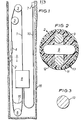
- Figure 2 is a cross section of one embodiment of the compensating member of Figure 1 along line 2 - 2;
- Figure 3 is a cross section of some of the metal particles of Figures 2 and 4;
- Figure 4 is a cross section of another embodiment of the compensating member of Figure 1 along line 2 - 2;
- Figure 5 is a cross section of still another embodiment of the compensating member of Figure 1 along line 2 - 2;
- Figure 6 is a cross section of an additional embodiment of the compensating member of Figure 1 along line 2 - 2;
- Figure 7 is a cross section of another embodiment of the compensating member of Figure 1 along line 2 - 2; and,
- Figure 8 is a cross section of an additional embodiment of the compensating member of Figure 1 along line 2 - 2.
- As shown in Figure 1, the
compensating cable 2 is connected to the bottom of car 8 and to the bottom ofcounterweight 4. Sometimes, but not always, the compensating cable may be traversed over compensatingsheave 6 or it may hang free in a loop likecontrol cable 10. (Seeelement 15 in dotted line). As a general rule, the length of compensating chain 2 (from car 8 to counterweight 4) should be essentially the same length ashoist rope 1, i.e., from car 8 oversheaves 3 to counterweight 9 (excluding wrap around portion around the sheave(s) if any).Hoist rope 1 is connected to the roof of car 8, traversed oversheave 3 and connected to the top ofcounterweight 4. Because of safety factor reasons, there may be five or more hoist ropes and the aggregate weight of such hoist ropes should approximately equal the weight of compensatingcable 2. This does not mean that if five hoist ropes are required, there must be five compensating cables. There may be only one compensating cable and a plurality of hoist ropes, so long as the length of compensating cable 2 (from car 8 to counterweight 4) is essentially the same as the length, but not the aggregate length, covered by all hoist ropes between car 8 andcounterweight 4 and its weight is essentially equal to the aggregate weight ofhoist ropes 1 andcontrol cable 10. The weight ofcontrol cable 10 is usually negligible comparative to that of the hoist ropes, it is terminated at junction box 7, and car 8, and is used to govern the car movement in a manner well known to the art. - Turning to Figure 2, shown by
element 2 is a cross section of one embodiment of compensatingcable 2.Plastic sheath 11 made from either a polyamide, a polyolefin, polyvinyl chloride, rubber, polyurethane or mixtures thereof, is primarily a tube in which there is disposedlink chain 9, composed of a plurality of links interconnected one to another. See U.S. Patent No.3,574,996 for an example. The volume delimited by the innermost surface ofsheath 11 not otherwise occupied by link chain 9 (hereinafter referred to as "the volume") is essentially occupied bymetal particles 13 suspended inplastic 12. The metal particles can be ferrous and nonferrous of any desirable particle size and shape, preferably between 0.50 and 1.0 mm in diameter in an amount so that 50 to 75 per cent of the volume is occupied by them. The balance of the volume is occupied byplastic 12, which may be of the same materials as listed above forsheath 11. - It will be noted that the outer surface of
sheath 11 is not necessarily undulating, as taught by the prior art, and may present an essentially circular cross section as shown in Figure 2, although it may be undulating if desired.Metal particles 13 result in a compensating cable having a greater weight per linear length than prior art chains. When prior art compensating chains are compared to compensating cable of the instant invention, it has been found that for a given equal length, a prior art compensating chain having links made of 9.525 mm diameter steel was equivalent to a compensating cable of the instant invention having a chain made of steel links of only 6.35 mm in diameter. Link chains made from high tensile strength non-metallic materials such as nylons and aramids are also suitable. Thelink chain 9 orwire rope 14 may be made of steel, iron, polyamides, aramids or graphite as appropriate. The links of the chain of the invention have a propensity to stay fully extended because offiller material sheath 11 and avoids the problem of sheath cracking, which is experienced when using chains of the type disclosed in U.S. Patent No.3,574,996. - The method of making the
compensating chain 2 involves apparatus and method steps known to the prior art. For example, U.S. Patent No.3,574,996 teaches the method and apparatus of extruding a sheath over a preform (a link chain). A preform composed oflink chain 9 and metalplastic volume plastic sheath 11 is extruded over the previously described preform. - Metals such as lead, iron, steel, copper and mixtures thereof have been found suitable for use in this invention having a preferred particle size so that all such particles will pass an opening of 1.00 mm, 10% maximum will not pass a screen opening of 0.84 mm, 85% minimum will not pass a screen opening of 0.60 mm and 97% minimum will not pass a screen opening of 0.50 mm. Some or all of such metal particles may be spherical and/or shapes other than spherical.
- In Figure 4 there is shown another embodiment of the invention using a stranded
metal wire rope 14 instead of alink chain 9. Most any commercially available wire rope has been found to be suitable, especially those made from twisted or stranded filaments of steel. Wire rope made from high tensile strength nylons and aramids are also suitable. Figures 5 and 6 disclose two additional embodiments of the invention employing a plurality of wire ropes (Figure 5) or link chains (Figure 6). Obviously there may be more than two link chains or wire ropes (see Figure 7) within a givensheath 11 and wire ropes may be substituted for link chains and treated as equivalents for purposes of this disclosure. - Shown in Figure 8 is a flat type embodiment of the compensating
cable 2. It is composed of a plurality of spaced apartstrength members 9 and/or 14, each with their respective axis arranged in a line and in substantially coplanar relationship with one another.Jacket 11 is made from a flexible material, examples of which have been previously discussed and contains a plurality ofelongated cavities 17, the longitudinal axes of which are alse arranged in a line and in substantially coplanar relationship with one another. Each of the cavities contains at least one strength member (9 and/or 14); they may alternatively contain two or more strength members like that shown in Figures 5, 6 and 7. The volume in the cavities not otherwise occupied by thestrength members 9 and/or 14 is substantially filled withmetal particles 13 and plastic 12 as previously described. Element numbers common to Figures 2, 3, 4, 5, 6, 7 and 8 represent like elements first described. - As mentioned earlier, most elevator systems do not employ a
bottom sheave 6, especially when the system is installed in a well orshaft 16. Systems installed in non-shaft or well situations where the compensating cable if left to hand free would be subject to wind or other forces usually employsheave 6 or its equivalent. Chain type compensating members of the prior art if installed in a shaft or well 16 have a tendency to come together at a link point in the general location whereloop 15 is shown. This arises out of the relatively limber nature of the chain and the restricted lateral space in theelevator shaft 16. The closer together the legs of compensatingmember 2 are to one another, the more likely a prior art compensating chain type member would exhibit this "point" tendency. It is at this point, which is a dynamic one as car 8 moves up and down, where one link strikes another, giving rise tc undesirable noise and abrasion and a tendency of one leg of the chain to slam into the car.
Claims (14)
Applications Claiming Priority (2)
| Application Number | Priority Date | Filing Date | Title |
|---|---|---|---|
| US405147 | 1982-08-04 | ||
| US06/405,147 US4716989A (en) | 1982-08-04 | 1982-08-04 | Elevator compensating cable |
Publications (3)
| Publication Number | Publication Date |
|---|---|
| EP0100583A2 true EP0100583A2 (en) | 1984-02-15 |
| EP0100583A3 EP0100583A3 (en) | 1985-11-27 |
| EP0100583B1 EP0100583B1 (en) | 1988-06-29 |
Family
ID=23602473
Family Applications (1)
| Application Number | Title | Priority Date | Filing Date |
|---|---|---|---|
| EP83302700A Expired EP0100583B1 (en) | 1982-08-04 | 1983-05-12 | A compensating cable for an elevator or the like |
Country Status (9)
| Country | Link |
|---|---|
| US (1) | US4716989A (en) |
| EP (1) | EP0100583B1 (en) |
| JP (1) | JPS5926878A (en) |
| AU (1) | AU550733B2 (en) |
| BR (1) | BR8302701A (en) |
| CA (1) | CA1176998A (en) |
| DE (1) | DE3377208D1 (en) |
| ES (1) | ES284869Y (en) |
| HK (1) | HK17394A (en) |
Cited By (11)
| Publication number | Priority date | Publication date | Assignee | Title |
|---|---|---|---|---|
| EP0207683A1 (en) * | 1985-06-28 | 1987-01-07 | Siecor Corporation | A compensating cable for an elevator or the like |
| EP0385255A1 (en) * | 1989-02-28 | 1990-09-05 | Otis Elevator Company | Rope weight compensating device for linear motor driven type elevator |
| EP0445019A3 (en) * | 1990-02-27 | 1992-08-05 | Thomson-Csf | Acoustic vibration reduction |
| US6364063B1 (en) * | 1996-12-30 | 2002-04-02 | Kone Corporation | Elevator rope arrangement |
| US6837340B2 (en) | 2000-10-20 | 2005-01-04 | Datwyler Ag | Compensation weights and elevator systems |
| WO2011135174A1 (en) | 2010-04-30 | 2011-11-03 | Kone Corporation | Elevator |
| CN102392375A (en) * | 2011-07-14 | 2012-03-28 | 南通海迅电梯部件有限公司 | Steel wire rope type balance and compensation cable for elevator |
| CN103395670A (en) * | 2013-08-13 | 2013-11-20 | 海安县社民机械配件厂 | All-plastic elastic anti-flaming elevator balanced compensation chain |
| CN104044981A (en) * | 2014-07-07 | 2014-09-17 | 南通迅达橡塑制造有限公司 | Novel elevator all-plastic balance chain |
| US9352935B2 (en) | 1998-02-26 | 2016-05-31 | Otis Elevator Company | Tension member for an elevator |
| CN109399421A (en) * | 2017-08-17 | 2019-03-01 | 张旻贞 | Balance rope for elevator |
Families Citing this family (40)
| Publication number | Priority date | Publication date | Assignee | Title |
|---|---|---|---|---|
| JPS6225041A (en) * | 1985-07-26 | 1987-02-03 | シバタ工業株式会社 | Composite body in which chain is buried in rubber and manufacture thereof |
| JPH0755780B2 (en) * | 1989-12-05 | 1995-06-14 | 三菱電機株式会社 | Traction type elevator equipment |
| US5125481A (en) * | 1990-09-26 | 1992-06-30 | Hideaki Shibata | Diagonal elevation apparatus |
| US5103937A (en) * | 1991-03-28 | 1992-04-14 | Robertson Leslie E | Sway minimization system for elevator cables |
| US5509503A (en) * | 1994-05-26 | 1996-04-23 | Otis Elevator Company | Method for reducing rope sway in elevators |
| US5492201A (en) * | 1994-08-29 | 1996-02-20 | Otis Elevator Company | Method and apparatus for installing and balancing an elevator car |
| US5788018A (en) * | 1997-02-07 | 1998-08-04 | Otis Elevator Company | Traction elevators with adjustable traction sheave loading, with or without counterweights |
| US7874404B1 (en) | 1998-09-29 | 2011-01-25 | Otis Elevator Company | Elevator system having drive motor located between elevator car and hoistway sidewall |
| IL132299A (en) * | 1998-10-23 | 2003-10-31 | Inventio Ag | Stranded synthetic fiber rope |
| CA2262307C (en) | 1999-02-23 | 2006-01-24 | Joseph Misrachi | Low stretch elevator rope |
| US6234277B1 (en) * | 1999-05-07 | 2001-05-22 | Draka Elevator Products, Inc. | Cable sway reduction device |
| IL136332A (en) * | 1999-06-11 | 2005-06-19 | Inventio Ag | Synthetic fiber rope |
| DK1199276T3 (en) * | 2000-10-20 | 2003-05-05 | Daetwyler Ag | Compensation weight and elevator system. |
| EP1234796B1 (en) * | 2001-02-27 | 2004-11-03 | Brugg Drahtseil AG | Arrangement for compensating cable |
| EP1384809A1 (en) * | 2002-07-22 | 2004-01-28 | N.V. Bekaert S.A. | Fixing of filaments in strand |
| DE10305275B4 (en) * | 2003-02-07 | 2005-05-25 | Wittur Ag | Elevator system with balancing of the suspension rope masses |
| MXPA03009456A (en) * | 2003-10-16 | 2005-04-21 | Luis Rodolfo Zamorano Morfin | Improvements to a passenger or freight lift based on the use of chains, counterweights and servomotors. |
| CN101065549B (en) * | 2004-11-24 | 2010-09-29 | 奥蒂斯电梯公司 | Joint construction for load bearing assembly |
| US7610994B2 (en) * | 2005-05-13 | 2009-11-03 | Draka Elevator Products | Elevator compensating cable having a selected loop radius and associated system and method |
| TW200744936A (en) * | 2005-11-28 | 2007-12-16 | Inventio Ag | Lift installation with equipment for compensation for the weight difference between the cage runs and the counterweight runs of the support means and method of realising such compensation |
| CN101016701B (en) * | 2007-02-15 | 2012-01-11 | 孟凡英 | Abrasion and cutting proof rope |
| GB2451296B (en) * | 2007-07-27 | 2011-07-20 | Henry Squire & Sons Holdings Ltd | Chain embedded in dense flexible plastic |
| BRPI0815201A2 (en) * | 2007-09-14 | 2015-03-31 | Thyssenkrupp Elevator Capital Corp | System and method for minimizing cable shake in elevators |
| JP5281883B2 (en) * | 2008-03-07 | 2013-09-04 | 株式会社日立製作所 | Elevator rope and elevator belt |
| CN102242508B (en) * | 2011-07-14 | 2013-02-06 | 南通海迅电梯部件有限公司 | Braided Elevator Balance Compensation Cable |
| CN102517940B (en) * | 2011-12-14 | 2016-06-29 | 朱思中 | Compensating cable of elevator |
| FI124242B (en) * | 2013-02-12 | 2014-05-15 | Kone Corp | Arrangements for dampening lateral oscillations of a line-like equipment attached to a lift unit and elevator |
| CN103865200B (en) * | 2014-03-19 | 2016-08-17 | 江苏德威新材料股份有限公司 | The preparation method of environment-friendly type high-speed elevator compensation chain protective cover material |
| CN204980724U (en) * | 2015-07-28 | 2016-01-20 | 江苏海迅实业集团股份有限公司 | Balanced compensation chain of elevator of belted steel ball |
| KR101917357B1 (en) * | 2016-04-21 | 2018-11-09 | 장민정 | Balancing lope |
| CN106436395B (en) * | 2016-09-13 | 2018-09-04 | 宣城市华菱精工科技股份有限公司 | A kind of elevator flame retardant type compensated cable |
| WO2018077654A1 (en) * | 2016-10-31 | 2018-05-03 | Inventio Ag | Lift system with sorted belt as compensation element for compensating the unladen weight of the supporting means |
| KR102657801B1 (en) | 2016-12-16 | 2024-04-17 | 오티스 엘리베이터 컴파니 | Elevator system suspension member |
| KR101984733B1 (en) * | 2017-12-18 | 2019-06-21 | (주) 코엘코 | Balancing lope |
| US12503338B2 (en) * | 2018-06-29 | 2025-12-23 | Otis Elevator Company | Hybrid compensation member |
| EP3623335B1 (en) * | 2018-09-12 | 2021-06-16 | KONE Corporation | A travelling cable support arrangement of an elevator and method for supporting travelling cables of an elevator |
| CN112096810B (en) * | 2020-06-19 | 2022-06-17 | 合立智能装备有限责任公司 | Rope chain combined transmission device |
| CN111810602B (en) * | 2020-06-19 | 2023-06-09 | 合立智能装备有限责任公司 | Rope-chain combined self-balancing transmission device |
| US11845312B2 (en) * | 2020-12-24 | 2023-12-19 | Robin N. Ward | Trailer chain safety device |
| US12459784B2 (en) * | 2024-01-10 | 2025-11-04 | Otis Elevator Company | Elevator system with compensation chains having variable densities |
Family Cites Families (13)
| Publication number | Priority date | Publication date | Assignee | Title |
|---|---|---|---|---|
| BE501611A (en) * | ||||
| DE28014C (en) * | JOH. BECKER 6 in Londorf b. Giefsen | Chain rope | ||
| US847228A (en) * | 1907-03-12 | John Lewis Bixby Jr | Belting. | |
| US1360456A (en) * | 1920-04-29 | 1920-11-30 | Elliott E Shiner | Reinforced belt |
| DE366479C (en) * | 1922-05-19 | 1923-01-08 | Felten & Guilleaume Carlswerk | Lower rope for head or other conveyance |
| FR1229203A (en) * | 1958-07-23 | 1960-09-05 | Rope and manufacturing process | |
| DE1781344C3 (en) * | 1968-09-30 | 1975-12-04 | Hanfwolf Wolf & C4, 4800 Bielefeld | Lower chord for weight compensation for elevator systems |
| US3574996A (en) * | 1969-01-17 | 1971-04-13 | August W Loos | Tubular sheathed chain |
| US3768596A (en) * | 1972-03-31 | 1973-10-30 | Westinghouse Electric Corp | Elevator compensation chains |
| JPS5424571B2 (en) * | 1973-01-29 | 1979-08-22 | ||
| US4243710A (en) * | 1978-12-06 | 1981-01-06 | Ferro Corporation | Thermoplastic electrode ink for the manufacture of ceramic multi-layer capacitor |
| US4247594A (en) * | 1979-04-30 | 1981-01-27 | Marshall & Pike Enterprises Inc. | Electrically conductive resinous composition |
| CH653290A5 (en) * | 1979-05-29 | 1985-12-31 | Ebnoether Ag | NON-TEXTILE WALL CLOTHING MATERIAL. |
-
1982
- 1982-08-04 US US06/405,147 patent/US4716989A/en not_active Expired - Lifetime
-
1983
- 1983-01-11 CA CA000419278A patent/CA1176998A/en not_active Expired
- 1983-03-04 JP JP58034726A patent/JPS5926878A/en active Granted
- 1983-04-18 AU AU13621/83A patent/AU550733B2/en not_active Ceased
- 1983-05-09 ES ES1983284869U patent/ES284869Y/en not_active Expired
- 1983-05-12 EP EP83302700A patent/EP0100583B1/en not_active Expired
- 1983-05-12 DE DE8383302700T patent/DE3377208D1/en not_active Expired
- 1983-05-23 BR BR8302701A patent/BR8302701A/en not_active IP Right Cessation
-
1994
- 1994-03-03 HK HK173/94A patent/HK17394A/en not_active IP Right Cessation
Cited By (16)
| Publication number | Priority date | Publication date | Assignee | Title |
|---|---|---|---|---|
| EP0207683A1 (en) * | 1985-06-28 | 1987-01-07 | Siecor Corporation | A compensating cable for an elevator or the like |
| EP0385255A1 (en) * | 1989-02-28 | 1990-09-05 | Otis Elevator Company | Rope weight compensating device for linear motor driven type elevator |
| US5074384A (en) * | 1989-02-28 | 1991-12-24 | Otis Elevator Company | Rope weight compensating device for a linear motor driven elevator |
| EP0445019A3 (en) * | 1990-02-27 | 1992-08-05 | Thomson-Csf | Acoustic vibration reduction |
| US6364063B1 (en) * | 1996-12-30 | 2002-04-02 | Kone Corporation | Elevator rope arrangement |
| US9352935B2 (en) | 1998-02-26 | 2016-05-31 | Otis Elevator Company | Tension member for an elevator |
| US6837340B2 (en) | 2000-10-20 | 2005-01-04 | Datwyler Ag | Compensation weights and elevator systems |
| CN102939256A (en) * | 2010-04-30 | 2013-02-20 | 通力股份公司 | elevator |
| EP2563704A4 (en) * | 2010-04-30 | 2016-02-24 | Kone Corp | ELEVATOR |
| CN102939256B (en) * | 2010-04-30 | 2016-05-04 | 通力股份公司 | Elevator |
| WO2011135174A1 (en) | 2010-04-30 | 2011-11-03 | Kone Corporation | Elevator |
| US9790054B2 (en) | 2010-04-30 | 2017-10-17 | Kone Corporation | Compensating rope for an elevator |
| CN102392375A (en) * | 2011-07-14 | 2012-03-28 | 南通海迅电梯部件有限公司 | Steel wire rope type balance and compensation cable for elevator |
| CN103395670A (en) * | 2013-08-13 | 2013-11-20 | 海安县社民机械配件厂 | All-plastic elastic anti-flaming elevator balanced compensation chain |
| CN104044981A (en) * | 2014-07-07 | 2014-09-17 | 南通迅达橡塑制造有限公司 | Novel elevator all-plastic balance chain |
| CN109399421A (en) * | 2017-08-17 | 2019-03-01 | 张旻贞 | Balance rope for elevator |
Also Published As
| Publication number | Publication date |
|---|---|
| US4716989A (en) | 1988-01-05 |
| JPH0355391B2 (en) | 1991-08-23 |
| EP0100583A3 (en) | 1985-11-27 |
| CA1176998A (en) | 1984-10-30 |
| ES284869Y (en) | 1987-07-16 |
| AU1362183A (en) | 1984-02-09 |
| AU550733B2 (en) | 1986-04-10 |
| JPS5926878A (en) | 1984-02-13 |
| ES284869U (en) | 1986-11-16 |
| DE3377208D1 (en) | 1988-08-04 |
| BR8302701A (en) | 1984-04-17 |
| EP0100583B1 (en) | 1988-06-29 |
| HK17394A (en) | 1994-03-11 |
Similar Documents
| Publication | Publication Date | Title |
|---|---|---|
| EP0100583B1 (en) | A compensating cable for an elevator or the like | |
| US4724929A (en) | Elevator compensating cable | |
| US4664229A (en) | Motion dampening compensating elevator cable | |
| CN100443660C (en) | Synthetic non-metallic rope for elevators | |
| US4445593A (en) | Flat type feeder cable | |
| JP4707788B2 (en) | Rope coating and method for forming the same | |
| JP3502350B2 (en) | Compensation weight and elevator system | |
| MXPA03005079A (en) | HIGH RESISTANCE, SLIM, WIRE ELEVATION CABLE WIRE. | |
| EP1478801A4 (en) | Synthetic fiber rope for an elevator | |
| BR0002617B1 (en) | synthetic fiber cable for the drive by means of a cable pulley. | |
| RU2003117082A (en) | ELEVATOR | |
| RU95102775A (en) | Load-bearing rope for hoists | |
| JP2001262482A (en) | Wire rope and elevator using it | |
| WO2004076327A1 (en) | An elevator rope | |
| WO2002000541A1 (en) | Pivoting termination for elevator rope | |
| US6837340B2 (en) | Compensation weights and elevator systems | |
| WO2002010050A1 (en) | Elevator device, and method of producing main cables for elevator devices | |
| CN210325273U (en) | Tensile wear-resistant flexible cable | |
| CN100439227C (en) | Elevator rope and elevator device | |
| CN103261077B (en) | Elevator system belt | |
| EP1721859B1 (en) | Elevator compensating cable having a selected loop radius and associated method | |
| KR100267286B1 (en) | Wire rope for controlling machine | |
| KR20210028059A (en) | Tension member and belt for elevator system | |
| SU831888A2 (en) | Load-lifting rope | |
| SU605877A1 (en) | Metal wire rope |
Legal Events
| Date | Code | Title | Description |
|---|---|---|---|
| PUAI | Public reference made under article 153(3) epc to a published international application that has entered the european phase |
Free format text: ORIGINAL CODE: 0009012 |
|
| AK | Designated contracting states |
Designated state(s): DE FR GB IT |
|
| 17P | Request for examination filed |
Effective date: 19850418 |
|
| PUAL | Search report despatched |
Free format text: ORIGINAL CODE: 0009013 |
|
| AK | Designated contracting states |
Designated state(s): DE FR GB IT |
|
| 17Q | First examination report despatched |
Effective date: 19870204 |
|
| GRAA | (expected) grant |
Free format text: ORIGINAL CODE: 0009210 |
|
| AK | Designated contracting states |
Kind code of ref document: B1 Designated state(s): DE FR GB IT |
|
| ITF | It: translation for a ep patent filed | ||
| REF | Corresponds to: |
Ref document number: 3377208 Country of ref document: DE Date of ref document: 19880804 |
|
| ET | Fr: translation filed | ||
| PLBE | No opposition filed within time limit |
Free format text: ORIGINAL CODE: 0009261 |
|
| STAA | Information on the status of an ep patent application or granted ep patent |
Free format text: STATUS: NO OPPOSITION FILED WITHIN TIME LIMIT |
|
| 26N | No opposition filed | ||
| ITTA | It: last paid annual fee | ||
| PGFP | Annual fee paid to national office [announced via postgrant information from national office to epo] |
Ref country code: DE Payment date: 20010508 Year of fee payment: 19 |
|
| PGFP | Annual fee paid to national office [announced via postgrant information from national office to epo] |
Ref country code: GB Payment date: 20010509 Year of fee payment: 19 |
|
| PGFP | Annual fee paid to national office [announced via postgrant information from national office to epo] |
Ref country code: FR Payment date: 20010518 Year of fee payment: 19 |
|
| REG | Reference to a national code |
Ref country code: FR Ref legal event code: CA |
|
| REG | Reference to a national code |
Ref country code: FR Ref legal event code: TP |
|
| REG | Reference to a national code |
Ref country code: GB Ref legal event code: IF02 |
|
| PG25 | Lapsed in a contracting state [announced via postgrant information from national office to epo] |
Ref country code: GB Free format text: LAPSE BECAUSE OF NON-PAYMENT OF DUE FEES Effective date: 20020512 |
|
| PG25 | Lapsed in a contracting state [announced via postgrant information from national office to epo] |
Ref country code: DE Free format text: LAPSE BECAUSE OF NON-PAYMENT OF DUE FEES Effective date: 20021203 |
|
| GBPC | Gb: european patent ceased through non-payment of renewal fee |
Effective date: 20020512 |
|
| PG25 | Lapsed in a contracting state [announced via postgrant information from national office to epo] |
Ref country code: FR Free format text: LAPSE BECAUSE OF NON-PAYMENT OF DUE FEES Effective date: 20030131 |
|
| REG | Reference to a national code |
Ref country code: FR Ref legal event code: ST |