EP0100501A2 - Vibration sensor - Google Patents
Vibration sensor Download PDFInfo
- Publication number
- EP0100501A2 EP0100501A2 EP83107244A EP83107244A EP0100501A2 EP 0100501 A2 EP0100501 A2 EP 0100501A2 EP 83107244 A EP83107244 A EP 83107244A EP 83107244 A EP83107244 A EP 83107244A EP 0100501 A2 EP0100501 A2 EP 0100501A2
- Authority
- EP
- European Patent Office
- Prior art keywords
- vibrator
- piezoelectric
- vibration sensor
- bonded
- plate
- Prior art date
- Legal status (The legal status is an assumption and is not a legal conclusion. Google has not performed a legal analysis and makes no representation as to the accuracy of the status listed.)
- Granted
Links
Images

Classifications
-
- G—PHYSICS
- G01—MEASURING; TESTING
- G01H—MEASUREMENT OF MECHANICAL VIBRATIONS OR ULTRASONIC, SONIC OR INFRASONIC WAVES
- G01H13/00—Measuring resonant frequency
-
- G—PHYSICS
- G01—MEASURING; TESTING
- G01H—MEASUREMENT OF MECHANICAL VIBRATIONS OR ULTRASONIC, SONIC OR INFRASONIC WAVES
- G01H11/00—Measuring mechanical vibrations or ultrasonic, sonic or infrasonic waves by detecting changes in electric or magnetic properties
- G01H11/06—Measuring mechanical vibrations or ultrasonic, sonic or infrasonic waves by detecting changes in electric or magnetic properties by electric means
- G01H11/08—Measuring mechanical vibrations or ultrasonic, sonic or infrasonic waves by detecting changes in electric or magnetic properties by electric means using piezoelectric devices
-
- H—ELECTRICITY
- H10—SEMICONDUCTOR DEVICES; ELECTRIC SOLID-STATE DEVICES NOT OTHERWISE PROVIDED FOR
- H10N—ELECTRIC SOLID-STATE DEVICES NOT OTHERWISE PROVIDED FOR
- H10N30/00—Piezoelectric or electrostrictive devices
- H10N30/30—Piezoelectric or electrostrictive devices with mechanical input and electrical output, e.g. functioning as generators or sensors
- H10N30/302—Sensors
Definitions
- the vibration sensor K' includes a bonded piezoelectric vibrator 3' having a pair of U-shaped slits 4' formed radially symmetrically in a side by side relationship with respect to each other such that a pair of rectangular vibrators 5' of a bending vibration mode are enclosed by the slits 4', respectively.
- the vibration sensor K' further includes a pair of upper electrodes la' and a pair of lower electrodes 2a' which are, respectively, provided on upper and lower faces of the bonded piezoelectric vibrator 3' in the same manner as described in the vibration sensor K.
- glassy adhesive can be used as inorganic adhesive for bonding the plate-like piezoelectric element to the mating metallic plate or the mating plate-like piezoelectric element.
- the glassy adhesive has such advantages that it is not carbonized even in a molten state in contrast with the organic adhesive, with the result that the above-described short-circuit between the electrodes of the bonded piezoelectric vibrator does not take place.
- a thin film of solder can be employed for soldering the inner electrodes to each other.
- the bonding faces of either one of the plate-like piezoelectric element and the metallic plate or either one of the plate-like piezoelectric elements, and the other one of the plate-like piezoelectric element and the metallic plate or the other one of the plate-like piezoelectric elements are, respectively, formed as an electrode on which gold is deposited, and as an electrode which is obtained by depositing silicon on a surface of gold such that eutectic bonding of gold and silicon takes place at temperatures of a few hundred degrees centigrade, whereby the plate-like piezoelectric element can be bonded to the mating metallic plate or the mating plate-like piezoelectric element.
Landscapes
- Physics & Mathematics (AREA)
- General Physics & Mathematics (AREA)
- Measurement Of Mechanical Vibrations Or Ultrasonic Waves (AREA)
- Gyroscopes (AREA)
Abstract
Description
- The present invention generally relates to vibration sensors for detecting elastic vibrations in vibrating members and more particularly, to a resonance type « vibration sensor and an acceleration sensor which are excellent in detection sensitivity at a predetermined frequency.
- Conventionally, rectangular bimorph piezoelectric vibrators of a bending vibration mode, having a cantilever configuration, in which the resonance frequencies are arranged to coincide with natural frequencies of vibrating members or the detection sensitivity is improved as compared with non-resonance type piezoelectric vibrators, and disk-like bimorph piezoelectric vibrators in which peripheral portions of the piezoelectric vibrators are fixedly supported through utilization of a surface bending mode of the disks have been widely employed in vibration sensors for detecting elastic vibrations in the vibrating members. Such known rectangular or disk-like piezoelectric vibrators have such advantages that the rectangular or disk-like piezoelectric elements can be manufactured accurately because of their simple shapes and their vibration modes can be easily analyzed and handled.
- However, the known piezoelectric vibrators have such an inconvenience that, although a portion of each of the piezoelectric vibrators must be stably clamped in order to stabilize their resonance frequencies, supporting members made of metals, etc. for fixedly supporting the portion of each of the piezoelectric vibrators are displaced due to stresses produced mechanically or for various causes such as temperature variations, etc. and thus, it is difficult to fixedly support the portion of each of the piezoelectric vibrators. Furthermore., the known piezoelectric vibrators have such a disadvantage that, since their resonance frequencies vary widely due to dimensional errors produced in machining or inaccurate assembly of their components during manufacturing processes thereof, adjustments for setting the known piezoelectric vibrators at the predetermined resonance frequencies are required to be made. Accordingly, in the case of the known rectangular bimorph piezoelectric vibrators, lengths of the vibrating portions are properly adjusted through cutting, grinding, etc. Meanwhile, in the case of the known disk-like bimorph piezoelectric vibrators, the above described adjustments are required to be made by replacing the supporting members, etc. Thus, in both of the prior art rectangular and disk-like bimorph piezoelectric vibrators, the adjustments for setting them at the predetermined resonance frequencies are complicated and considerably troublesome. Furthermore, the prior art rectangular and disk-like bimorph piezoelectric vibrators have been disadvantageous in that it is difficult to perform the manufacturing operations since clamping conditions of the piezoelectric vibrators vary in accordance with clamping forces of the supporting members, with the result that the piezoelectric elements are damaged in the case where the clamping forces of the supporting members are too large.
- Accordingly, an essential object of the present invention is to provide an improved vibration sensor which can stably detect elastic vibrations in vibrating members, with substantial elimination of the disadvantages inherent in conventional vibration sensors of this kind.
- Another important object of the present invention is to provide an improved vibration sensor of the above described type which is simple in structure, highly reliable in actual use and suitable for mass production at low cost.
- In accomplishing these and other objects according to one preferred embodiment of the present invention, there is provided an improved vibration sensor comprising: a piezoelectric vibrator constituted by a pair of first and second plate-like piezoelectric elements bonded to each other; said first and second piezoelectric elements having a polarization axis aligned in a direction of thickness thereof; and a vibrator of a bending vibration mode, which is subjected to resonance at a predetermined frequency and is locally provided in said piezoelectric vibrator such that a portion of said piezoelectric vibrator, disposed peripherally of said vibrator of the bending vibration mode, is fixedly supported.
- In accordance with the present invention, since the vibrator of the bending vibration mode is locally provided in the piezoelectric vibrator, the portion of the piezoelectric vibrator, disposed peripherally of the vibrator of the bending vibration mode, can be clamped more securely than those of the conventional piezoelectric vibrators of the cantilever configurations, thus stabilizing the resonance frequency of the vibrator of the bending vibration mode.
- These and other objects and features of the present invention will become apparent from the foregoing description taken in conjunction with the preferred embodiment thereof with reference to the accompanying drawings, in which:
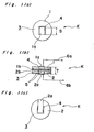
- Figs. l(a), l(b) and l(c) are a top plan view, a cross-sectional view and a bottom plan view of a main portion of a vibration sensor according to a first embodiment of the present invention, respectively;
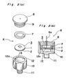
- Figs. 2 (a) and 2(b) are an exploded perspective view and a cross-sectional view of the vibration sensor of Fig. l(a), respectively;
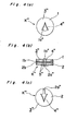
- Figs. 3(a), 3(b) and 3(c) are a top plan view, a cross-sectional view and a bottom plan view of a main portion of a vibration sensor according to a second embodiment of the present invention, respectively;
- Figs. 4(a), 4(b) and 4(c) are a top plan view, a cross-sectional view and a bottom plan view of a main portion of a vibration sensor according to a third embodiment of the present invention, respectively;
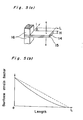
- Fig. 5(a) is a perspective view of a rectangular cantilever type vibrator of a bending vibration mode; and
- Fig. 5(b) is a graph explanatory of surface strain factors against lengths of a vibrating portion of the vibrator of Fig. 5(a).
- Before the description of the present invention proceeds, it is to noted that like parts are designated by like reference numerals throughout several views of the accompanying drawings.
- Referring now to the drawings, there is shown in Figs. 1(a) to l(c), a vibration sensor K according to a first embodiment of the present invention. As shown in Fig. l(b), the vibration sensor K includes a pair of disk-like
piezoelectric elements piezoelectric elements piezoelectric vibrator 3, with the inner electrodes lb and 2b being provided on inner faces of thepiezoelectric elements piezoelectric vibrator 3 has aU-shaped slit 4 formed at a central portion thereof by a laser processing machine, etc. and extending therethrough. A rectangular upper electrode la is provided on an outer face of thepiezoelectric element 1 remote from the inner electrode lb so as to be enclosed by theslit 4. Meanwhile, a substantially rectangularlower electrode 2a is provided on an outer face of thepiezoelectric element 2 remote from theinner electrode 2b so as to extend linearly and continuously from a portion enclosed by theslit 4 to a peripheral edge portion of thepiezoelectric element 2. Namely, the bondedpiezoelectric vibrator 3 has the upper electrode la and thelower electrode 2a provided on upper and lower faces thereof, respectively. - When a peripheral portion of the bonded
piezoelectric vibrator 3, extending from portions disposed peripherally of theslit 4 to a peripheral edge of the bondedpiezoelectric vibrator 3, is supported, as a supported portion, by supporting members, a rectangular portion of the bondedpiezoelectric vibrator 3, enclosed by theslit 4, functions as a so-calledcantilever type vibrator 5 of a bending vibration mode. An output voltage generated through vibration of thevibrator 5 of the bending vibration mode is applied between the upper electrode la and thelower electrode 2a of the bondedpiezoelectric vibrator 3 and is further taken out bylead wires lower electrode 2a. - Assuming that the
vibrator 5 of the bending vibration mode has a thickness T and a length S, a resonance frequency Fr of thevibrator 5 is proportional to a value of T/S 2. Accordingly, thevibrator 5 can be set at a • predetermined resonance frequency by properly determining values of the thickness T and the length S. - In the above described arrangement of the vibration sensor K, since the
vibrator 5 of the bending vibration mode is locally provided in the bondedpiezoelectric vibrator 3, variations of the resonance frequency of thevibrator 5 of the bending vibration mode, resulting from changes in clamping conditions of the supported portion of the bondedpiezoelectric vibrator 3, are kept minimal, so that the resonance frequency of thevibrator 5 of the bending vibration mode is made stable. Namely, variations of the resonance frequency of thevibrator 5 of the bending vibration mode, resulting from, for example, displacement of the supported portion of the bondedpiezoelectric vibrator 3 due to stresses produced mechanically or for other causes such as temperature variations, etc., are kept minimal, so that the resonance frequency of thevibrator 5 of the bending vibration mode is made stable. Meanwhile, in the vibration sensor K, since the supporting members are not required to be positioned so accurately, the vibration sensor K can be assembled easily. Furthermore, since thevibrator 5 of the bending vibration mode is locally provided in the bondedpiezoelectric vibrator 3, the bondedpiezoelectric vibrator 3 is not formed, at the upper and lower faces, with projections which are provided in conventional cantilever type vibrators, so that damage to the vibration sensor K through improper handling thereof can be advantageously eliminated. Moreover,-since adjustments for setting thevibrator 5 of the bending vibration mode at the predetermined resonance frequency can be easily made by trimming the vibrating portion with a laser processing machine without the need for partially grinding the vibrating portions in conventional vibration sensors, the vibration sensor K is suitable for mass production. - Referring now to Figs. 2 (a) and 2 (b), the vibration sensor K includes a metallic supporting
member 10 for supporting the bondedpiezoelectric vibrator 3, which has a male screw portion 11 formed at one end thereof and threadingly inserted into a vibrating member, astepped hole 12 formed at the other end thereof remote from the male screw portion 11, and afemale screw portion 13 formed at an inlet of thestepped hole 12. The vibration sensor K further includes an annular supportingmember 7 and aclamping member 8 having amale screw portion 9 engageable with thefemale screw portion 13 of the supportingmember 10. After the bondedpiezoelectric vibrator 3 has been inserted into the stepped hole 12.of the supportingmember 10 such that the lower face of the bondedpiezoelectric vibrator 3 is brought into contact with an annularintermediate bottom 12a of thestepped hole 12, the supportingmember 7 is clamped onto an annular peripheral portion of the upper face of the bondedpiezoelectric vibrator 3 by theclamping member 8 through engagement of 4 themale screw portion 9 of theclamping member 8 with the female screw,portion 13 of the supportingmember 10, whereby the bondedpiezoelectric vibrator 3 is fixedly supported. Since thelower electrode 2a provided on the lower face of the bondedpiezoelectric vibrator 3 is fixedly supported by the supportingmember 10, thelower electrode 2a is electrically connected to the supportingmember 10 and thus, the supportingmember 10 is used as one terminal for taking out the output voltage of thevibrator 5 of the bending vibration mode. Thelead wire 6a extending from the upper electrode la of the bondedpiezoelectric vibrator 3 is used as the other terminal for thevibrator 5 of the bending vibration mode. - Referring to Figs. 3(a) to 3(c), there is shown a vibration sensor K' according to a second embodiment of the present invention. The vibration sensor K' includes a bonded piezoelectric vibrator 3' having a pair of U-shaped slits 4' formed radially symmetrically in a side by side relationship with respect to each other such that a pair of rectangular vibrators 5' of a bending vibration mode are enclosed by the slits 4', respectively. The vibration sensor K' further includes a pair of upper electrodes la' and a pair of
lower electrodes 2a' which are, respectively, provided on upper and lower faces of the bonded piezoelectric vibrator 3' in the same manner as described in the vibration sensor K. In the vibration sensor K', when a resonance frequency of one vibrator 5' of the bending vibration mode is made equal to that of the other vibrator 5'; its detection sensitivity at a predetermined vibration frequency can be enhanced. Meanwhile, when the vibrators 5' of the bending vibration mode are, respectively, set at different resonance frequencies correlated to each other, its detection accuracy is improved. - Referring to Figs. 4(a) to 4(c), there is shown a vibration sensor K" according to a third embodiment of the present invention. The vibration sensor K" includes a bonded
piezoelectric vibrator 3" having a substantiallytriangular slit 4" formed at a central portion thereof such that avibrator 5" of a bending vibration mode, enclosed by theslit 4", is formed into a triangular shape. The vibration sensor K" further includes a triangular upper electrode 1a" and an arrow-shapedlower electrode 2a" which are, respectively, provided on upper and lower faces of the bonded piezoelectric vibrator 3'' in the same manner as described in the vibration sensor K. - Since other constructions of the vibration sensors K' and K" are similar to those of the vibration sensor K, description thereof is abbreviated. for brevity.
- Hereinbelow, a rectangular vibrator of a bending vibration mode having a cantilever configuration, will be described with reference to Figs. 5(a) and 5(b). As shown in Fig. 5(a), the vibrator includes a pair of rectangular
piezoelectric elements members 16 such that one side face-of.each of the supportingmembers 16 is flush with one end of the vibrator. Assuming that a length L of a vibrating portion of the vibrator for detecting vibrations of a vibrating member is measured from the other side face of each of the supportingmembers 16 remote from the one end of the vibrator towards the other end of the vibrator and the vibrating portion has a thickness H, surface strain factors at the vibrating portion are illustrated by the curved solid line in Fig. 5(b). Meanwhile, the linear broken line in Fig. 5(b) approximately illustrates the surface strain factors at the vibration portion by connecting opposite ends of the curved solid line in Fig. 5(b). It will be readily understood from Fig. 5(b) that the surface strain factors at the vibration portion of the vibrator of the bending vibration mode reach a maximum value at the time when the length L is zero, namely, at the starting-point of the length L. Consequently, when an extremely large force is applied to the vibrator, a portion of the vibrator, adjacent to the supportingmembers 16, is most readily damaged. - Accordingly, in the present invention, it is so arranged that the
slit 4" of the vibration sensor K'' is formed on the bondedpiezoelectric vibrator 3" by the use of a laser processing machine, etc. such that a vibrating portion of thevibrator 5" of the bending vibration mode for detecting vibrations of a vibrating member has an area proportional to the surface strain factors shown in Fig. 5(b): Namely, since a portion of the vibrating portion of thevibrator 5", which has a large surface strain factor, is increased in area while another portion of the vibrating portion of the vibrator 5'', which has a small surface strain factor, is decreased in area, the vibrating portion of thevibrator 5" has a uniform surface strain factor. Accordingly, when a force is applied to a whole of the vibrating portion, a portion of the vibrating portion, adjacent to the supporting members, can be more effectively prevented from being damaged than those of the conventional rectangular vibrators of the bending vibration mode. Furthermore, since the vibrating portion of thevibrator 5" has the uniform surface strain factor, operational characteristics of the vibration sensor K" can be kept stable for a long time. - Meanwhile, numerical control units are widely employed in machine tools such as a laser processing machine, etc. but, in some cases, enable only linear cutting and cutting of circular interpolation, the consequence of which is that considerably complicated programs are required for machining arbitrary curves. In such cases, when the vibrator of the bending vibration mode is so manufactured as to have a surface strain factor corresponding to that shown in the broken line in Fig. 5(b), the surface strain factor of the vibrator of the bending vibration mode can be made more uniform than those of the conventional vibrators of the • bending vibration mode.
- Moreover, when it is so arranged that, in order to increase mechanical strength of the bonded piezoelectric vibrator, the bonded piezoelectric vibrator is constituted by a plate-like piezoelectric element and a metallic plate each having a polarization axis aligned in a direction of thickness thereof or by a pair of plate-like piezoelectric elements each having a polarization axis aligned in a direction of thickness thereof in which direction a metallic plate is interposed therebetween, the same effect as described above can be obtained.
- In the case where the plate-like piezoelectric element is bonded to the mating metallic plate or the mating plate-like piezoelectric element by the use of organic adhesive in the bonded piezoelectric vibrator, the organic adhesive is carbonized through irradiation of laser beam thereto, so that the carbonized organic adhesive is caused to adhere to opposite wall faces of the slit, thereby incurring a high possibility that the inner electrodes disposed at the bonding faces of the bonded piezoelectric vibrator are short-circuited to the respective upper and lower electrodes of the bonded piezoelectric vibrator. In order to eliminate such a phenomenon, for example, glassy adhesive can be used as inorganic adhesive for bonding the plate-like piezoelectric element to the mating metallic plate or the mating plate-like piezoelectric element. The glassy adhesive has such advantages that it is not carbonized even in a molten state in contrast with the organic adhesive, with the result that the above-described short-circuit between the electrodes of the bonded piezoelectric vibrator does not take place. Furthermore, in place of the glassy adhesive, a thin film of solder can be employed for soldering the inner electrodes to each other. Moreover, when it is so arranged that the bonding faces of either one of the plate-like piezoelectric element and the metallic plate or either one of the plate-like piezoelectric elements, and the other one of the plate-like piezoelectric element and the metallic plate or the other one of the plate-like piezoelectric elements are, respectively, formed as an electrode on which gold is deposited, and as an electrode which is obtained by depositing silicon on a surface of gold such that eutectic bonding of gold and silicon takes place at temperatures of a few hundred degrees centigrade, whereby the plate-like piezoelectric element can be bonded to the mating metallic plate or the mating plate-like piezoelectric element.
- As is clear from the foregoing description, in accordance with the present invention, since the vibrator of the bending vibration mode is locally provided in the bonded piezoelectric vibrator, the portion of the piezoelectric vibrator, disposed peripherally of the vibrator of the bending vibration mode, can be clamped more securely than those of the conventional piezoelectric vibrators of the cantilever configuration, so that the resonance frequency of the vibrator of the bending vibration mode can be kept stable. -Furthermore, in accordance with the present invention, the vibration sensor is made suitable for mass production.
- Although the present invention has been fully described by way of example with reference to the accompanying drawings, it is to be noted here that various changes and modifications will be apparent to those skilled in the art. Therefore unless otherwise such changes and modifications depart from the scope of the present invention, they should be construed as included therein.
Claims (8)
Applications Claiming Priority (6)
| Application Number | Priority Date | Filing Date | Title |
|---|---|---|---|
| JP132732/82 | 1982-07-28 | ||
| JP57132732A JPS5923223A (en) | 1982-07-28 | 1982-07-28 | vibration sensor |
| JP180736/82 | 1982-10-14 | ||
| JP57180726A JPS5970923A (en) | 1982-10-14 | 1982-10-14 | vibration sensor |
| JP180726/82 | 1982-10-14 | ||
| JP57180736A JPS5970924A (en) | 1982-10-14 | 1982-10-14 | vibration sensor |
Publications (3)
| Publication Number | Publication Date |
|---|---|
| EP0100501A2 true EP0100501A2 (en) | 1984-02-15 |
| EP0100501A3 EP0100501A3 (en) | 1985-08-28 |
| EP0100501B1 EP0100501B1 (en) | 1989-02-08 |
Family
ID=27316567
Family Applications (1)
| Application Number | Title | Priority Date | Filing Date |
|---|---|---|---|
| EP83107244A Expired EP0100501B1 (en) | 1982-07-28 | 1983-07-23 | Vibration sensor |
Country Status (2)
| Country | Link |
|---|---|
| EP (1) | EP0100501B1 (en) |
| DE (1) | DE3379175D1 (en) |
Cited By (4)
| Publication number | Priority date | Publication date | Assignee | Title |
|---|---|---|---|---|
| GB2156523A (en) * | 1984-03-19 | 1985-10-09 | Draper Lab Charles S | Planar inertial sensor |
| US5003824A (en) * | 1989-12-26 | 1991-04-02 | Matsushita Electric Industrial Co., Ltd. | Vibration/acceleration sensor |
| US5053671A (en) * | 1987-11-16 | 1991-10-01 | Nissan Motor Company, Limited | Piezoelectric sensor for monitoring kinetic momentum |
| US5365799A (en) * | 1991-07-17 | 1994-11-22 | Kazuhiro Okada | Sensor for force/acceleration/magnetism using piezoelectric element |
Family Cites Families (4)
| Publication number | Priority date | Publication date | Assignee | Title |
|---|---|---|---|---|
| US2769867A (en) * | 1947-02-07 | 1956-11-06 | Sonotone Corp | Dielectrostrictive signal and energy transducers |
| NL7807172A (en) * | 1978-06-30 | 1980-01-03 | Philips Nv | Electroacoustic transducer driven by piezoelectric element - has diaphragm mounted on frame with device made from ceramic material stuck on it |
| FR2441959A1 (en) * | 1978-11-16 | 1980-06-13 | Suisse Horlogerie | PIEZOELECTRIC DIAPASON RESONATOR |
| FR2441960A1 (en) * | 1978-11-16 | 1980-06-13 | Suisse Horlogerie | PIEZOELECTRIC RESONATOR WORKING IN THICKNESS SHEAR |
-
1983
- 1983-07-23 EP EP83107244A patent/EP0100501B1/en not_active Expired
- 1983-07-23 DE DE8383107244T patent/DE3379175D1/en not_active Expired
Cited By (5)
| Publication number | Priority date | Publication date | Assignee | Title |
|---|---|---|---|---|
| GB2156523A (en) * | 1984-03-19 | 1985-10-09 | Draper Lab Charles S | Planar inertial sensor |
| US5053671A (en) * | 1987-11-16 | 1991-10-01 | Nissan Motor Company, Limited | Piezoelectric sensor for monitoring kinetic momentum |
| US5003824A (en) * | 1989-12-26 | 1991-04-02 | Matsushita Electric Industrial Co., Ltd. | Vibration/acceleration sensor |
| EP0434878A1 (en) * | 1989-12-26 | 1991-07-03 | Matsushita Electric Industrial Co., Ltd. | Vibration/acceleration sensor |
| US5365799A (en) * | 1991-07-17 | 1994-11-22 | Kazuhiro Okada | Sensor for force/acceleration/magnetism using piezoelectric element |
Also Published As
| Publication number | Publication date |
|---|---|
| DE3379175D1 (en) | 1989-03-16 |
| EP0100501B1 (en) | 1989-02-08 |
| EP0100501A3 (en) | 1985-08-28 |
Similar Documents
| Publication | Publication Date | Title |
|---|---|---|
| US4836023A (en) | Vibrational angular rate sensor | |
| US5081867A (en) | Semiconductor sensor | |
| US5811693A (en) | Force detector and acceleration detector and method of manufacturing the same | |
| US4658650A (en) | Vibration and acoustic wave detecting device employing a piezoelectric element | |
| US20030024328A1 (en) | Force detector and acceleration detector and method of manufacturing the same | |
| US4193647A (en) | Piezoelectric ceramic transducers with uniform resonant frequency | |
| EP0100501B1 (en) | Vibration sensor | |
| US4503350A (en) | Piezoelectric resonator device with a laminated structure | |
| US5539319A (en) | Surface potential electrometer | |
| US4441370A (en) | Vibration sensor | |
| US4178526A (en) | Piezoelectrically driven tuning fork resonator and mounting structure | |
| US7535158B2 (en) | Stress sensitive element | |
| JPH0256619B2 (en) | ||
| JPH0687835U (en) | Torque sensor | |
| US20030085637A1 (en) | Crystal element for piezo sensors | |
| JPS5970924A (en) | vibration sensor | |
| JPH0257252B2 (en) | ||
| US20260063661A1 (en) | Physical Quantity Sensor | |
| JP3038692B2 (en) | Bimorph vibrator and piezoelectric acceleration sensor | |
| JP2559708B2 (en) | Piezoelectric vibrator | |
| JPH0132453B2 (en) | ||
| JPS6033284B2 (en) | Electrical component manufacturing method | |
| RU1781620C (en) | Piezoelectric accelerometer | |
| JPS61266931A (en) | Pressure sensor | |
| JP2001133474A (en) | Acceleration sensor and method of manufacturing the same |
Legal Events
| Date | Code | Title | Description |
|---|---|---|---|
| PUAI | Public reference made under article 153(3) epc to a published international application that has entered the european phase |
Free format text: ORIGINAL CODE: 0009012 |
|
| AK | Designated contracting states |
Designated state(s): DE FR GB |
|
| PUAL | Search report despatched |
Free format text: ORIGINAL CODE: 0009013 |
|
| AK | Designated contracting states |
Designated state(s): DE FR GB |
|
| 17P | Request for examination filed |
Effective date: 19851217 |
|
| 17Q | First examination report despatched |
Effective date: 19870330 |
|
| GRAA | (expected) grant |
Free format text: ORIGINAL CODE: 0009210 |
|
| AK | Designated contracting states |
Kind code of ref document: B1 Designated state(s): DE FR GB |
|
| REF | Corresponds to: |
Ref document number: 3379175 Country of ref document: DE Date of ref document: 19890316 |
|
| ET | Fr: translation filed | ||
| PLBE | No opposition filed within time limit |
Free format text: ORIGINAL CODE: 0009261 |
|
| STAA | Information on the status of an ep patent application or granted ep patent |
Free format text: STATUS: NO OPPOSITION FILED WITHIN TIME LIMIT |
|
| 26N | No opposition filed | ||
| PGFP | Annual fee paid to national office [announced via postgrant information from national office to epo] |
Ref country code: GB Payment date: 19930528 Year of fee payment: 11 |
|
| PGFP | Annual fee paid to national office [announced via postgrant information from national office to epo] |
Ref country code: DE Payment date: 19930727 Year of fee payment: 11 |
|
| PGFP | Annual fee paid to national office [announced via postgrant information from national office to epo] |
Ref country code: FR Payment date: 19930729 Year of fee payment: 11 |
|
| PG25 | Lapsed in a contracting state [announced via postgrant information from national office to epo] |
Ref country code: GB Effective date: 19940723 |
|
| GBPC | Gb: european patent ceased through non-payment of renewal fee |
Effective date: 19940723 |
|
| PG25 | Lapsed in a contracting state [announced via postgrant information from national office to epo] |
Ref country code: FR Effective date: 19950331 |
|
| PG25 | Lapsed in a contracting state [announced via postgrant information from national office to epo] |
Ref country code: DE Effective date: 19950401 |
|
| REG | Reference to a national code |
Ref country code: FR Ref legal event code: ST |