EP0099276B1 - Procédé d'analyse de données diffusées, analyseur de réseau mettant en oeuvre un tel procédé, et équipement de réception utilisant un tel analyseur - Google Patents
Procédé d'analyse de données diffusées, analyseur de réseau mettant en oeuvre un tel procédé, et équipement de réception utilisant un tel analyseur Download PDFInfo
- Publication number
- EP0099276B1 EP0099276B1 EP83401159A EP83401159A EP0099276B1 EP 0099276 B1 EP0099276 B1 EP 0099276B1 EP 83401159 A EP83401159 A EP 83401159A EP 83401159 A EP83401159 A EP 83401159A EP 0099276 B1 EP0099276 B1 EP 0099276B1
- Authority
- EP
- European Patent Office
- Prior art keywords
- data
- mode
- analyzer
- analyzing
- analysis
- Prior art date
- Legal status (The legal status is an assumption and is not a legal conclusion. Google has not performed a legal analysis and makes no representation as to the accuracy of the status listed.)
- Expired
Links
- 238000000034 method Methods 0.000 title claims description 29
- 238000004458 analytical method Methods 0.000 claims description 55
- 230000015654 memory Effects 0.000 claims description 27
- 238000012545 processing Methods 0.000 claims description 25
- 230000005540 biological transmission Effects 0.000 claims description 12
- 238000012800 visualization Methods 0.000 claims description 10
- 238000005259 measurement Methods 0.000 claims description 9
- 230000006870 function Effects 0.000 claims description 7
- 230000002452 interceptive effect Effects 0.000 claims description 4
- 238000013500 data storage Methods 0.000 claims 1
- 230000003407 synthetizing effect Effects 0.000 claims 1
- 230000015572 biosynthetic process Effects 0.000 description 19
- 238000003786 synthesis reaction Methods 0.000 description 19
- 230000008569 process Effects 0.000 description 17
- 238000012360 testing method Methods 0.000 description 9
- 238000010586 diagram Methods 0.000 description 7
- 238000012544 monitoring process Methods 0.000 description 4
- 230000004044 response Effects 0.000 description 4
- 238000009792 diffusion process Methods 0.000 description 3
- 241000135309 Processus Species 0.000 description 2
- 238000003012 network analysis Methods 0.000 description 2
- 230000008520 organization Effects 0.000 description 2
- 241001080024 Telles Species 0.000 description 1
- 238000004364 calculation method Methods 0.000 description 1
- 230000008859 change Effects 0.000 description 1
- 239000002131 composite material Substances 0.000 description 1
- 238000011161 development Methods 0.000 description 1
- 238000012986 modification Methods 0.000 description 1
- 230000004048 modification Effects 0.000 description 1
- 230000000717 retained effect Effects 0.000 description 1
- 238000000926 separation method Methods 0.000 description 1
- 230000001360 synchronised effect Effects 0.000 description 1
- 238000010998 test method Methods 0.000 description 1
- 238000011282 treatment Methods 0.000 description 1
Images


Classifications
-
- H—ELECTRICITY
- H04—ELECTRIC COMMUNICATION TECHNIQUE
- H04N—PICTORIAL COMMUNICATION, e.g. TELEVISION
- H04N17/00—Diagnosis, testing or measuring for television systems or their details
- H04N17/004—Diagnosis, testing or measuring for television systems or their details for digital television systems
Definitions
- the invention relates to data broadcasting networks and more particularly to a method for analyzing the broadcast data and to a test tool, known as a "network analyzer", implementing such a method, suitable for conventional reception equipment. .
- the broadcasting of the data can be a broadcast by radio, a cable distribution, or a satellite broadcast. Given this diversity and the large number of reception points, it appeared the need for a test tool easy to integrate with the reception equipment, making it possible to carry out link quality measurements from the data received. and monitor the network, viewing the results.
- the subject of the invention is a method for analyzing broadcast data and a network analyzer meeting this need.
- the invention also relates to a network analyzer implementing such a method.
- teletext type data broadcasting networks The purpose of teletext type data broadcasting networks is to display, on a television receiver, texts made up of alphabetic and numeric characters, or simple graphics.
- the corresponding data are transmitted by the transmitters of television networks, either on the same channel as normal television programs and without altering the latter, or by using a special channel.
- Users must have a suitable television set and associated terminal equipment, for demodulation and decoding, from which they can control the appearance on the receiver of a page or of a succession of pages selected from the set of messages transmitted.
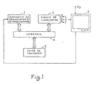
- a decoder whose input is coupled to the output S D of the broadcasting channel delivers on its output the broadcast data by separating the useful data from the other data possibly passing through the same broadcast channel.
- the decoder part comprises a demodulation and demultiplexing device 1 which separates the digital data transmitted by the television network from normal programs when these data are transmitted on a channel also used for a normal program .
- the decoder further comprises a digital data processing unit 2 coupled to the output of the demodulation and demultiplexing device 1 by an interface 4.
- the equipment comprises a display circuit 3 coupled to the output of the processing unit 2 via interface 4, which directly supplies color video signals, red R, green V, and blue B, controlling the display of data on the tube of a receiver 5.
- the network analyzer according to the invention is included in this terminal equipment to carry out on demand tests, measurements, or monitoring of the data transmitted by the network and received by the equipment; this analyzer directly controls the receiving tube to visualize in a synthetic form the information concerning the digital data acquired, after having subjected them to a processing which puts them in a form suitable for this display by following one of the operating modes recognized by the terminal for the display, ie conventionally the alphamosa ⁇ c mode, the alphageometric mode, or the alphaphotographic mode.
- the processing unit 2 of the team the terminal is programmed with data processing tasks present at the output of the demodulation and demultiplexing device, and tasks of coding the results of these processing tasks for the display of these results, via the circuit of visualization.
- the terminal equipment itself is then a tool for testing data, a tool for monitoring a data broadcasting network, or even a tool for measuring the quality of the level of data broadcasting.
- the network analyzer can operate by following a transparent mode of analysis and display of the data as received by the decoder. This type of network analysis is very useful in particular during the stages of development and fine-tuning of equipment in the distribution chain.
- the analyzer secondly comprises means for entering all the specific parameters of the data signal, and means for synthetic display of all of these parameters. This monitoring is carried out automatically by the use of the terminal control device, for example, a remote control keyboard.
- the network analyzer thirdly comprises measurement means, these measurements being carried out during measurement campaigns.
- the measurement points within the network will be chosen all the more easily to determine the representative sample of the network as each television set equipped with a suitable decoder constitutes a possible measurement point.
- process B react to the user's commands and exploit the information resulting from the analysis by process A to synthesize an image in response transmitted to the receiving tube.
- these two processes can be executed in parallel.
- the computing power of the processing unit 2 may be insufficient to properly carry out these two processes in parallel when the data rate received at the input of the demodulation device 1 is high.
- the means of implementing the network analysis are close to those conventionally used for receiving the transmitted data.
- the demodulation and demultiplexing device 1 comprises a demodulator 11 receiving the composite signal (video + data), and a control signal (window) for selecting the data to be demodulated.
- the output of this demodulator is connected to the input of a demultiplexer 12 performing the separation of the data signals.
- the demodulated and separate signals are then stored in a FIFO memory, 13, from which they are extracted, on command, by the processing unit 2.
- the output of the demultiplexer is coupled via the interface 4 to the bus 21 of the processing unit 2.
- This interface 4 mainly comprises a general data transmission bus 41 and an interface circuit 42.
- the processing unit further comprises a PROM program memory 22 with a capacity of 8K bytes for example , a processing unit MPU 23 constituted by a microprocessor of type 6809 for example, a random access memory RAM, 24, and a circuit for processing commands received from the keyboard 25 coupled to the bus 21.
- the command keyboard can transmit for example infrared IR signals.
- This display circuit comprises a character generator 31, coupled to the general bus 41 of the interface 4. This generator is also coupled to the bus 32 of the display unit, to which is coupled the display unit 33 which supplies the color components R, G, B applied to the tube, depending on the characters to be displayed.
- An extension game memory 34 and a refresh memory 35 are also coupled to the bus 32.
- the display unit 33 receives the frame synchronization signal SYT from the television set; the line synchronization signal SYL of this same television set is received at the control input of a phase loop 36 which supplies the clock signal H to the display unit. This display unit supplies a line signal S L to the phase loop 36.
- this general scheme could be that of a conventional decoder for teletext reception equipment, ANTIOPE for example.
- PROM memory 22 associated with the microprocessor 23 of the processing unit 2 controls the tasks and the transfers indicated schematically in FIG. 3.
- a task distributor 100 coordinates the sequence of the two processes and more precisely the sequence of the tasks which compose them.
- the programmable channel selector, or coupler 112 selects from the data it receives from the demodulator 11 those which must be retained, the selector comprising for this purpose a control input C 112 .
- These selected data present at the output of this selector are transmitted to the memory 13, of capacity 1 K bytes for example.
- the analysis task T A takes these data from the buffer memory 13 and analyzes them according to one of the three possible analysis modes. The flowchart for this analysis task is shown in Figure 4 described below.
- the data resulting from the analysis are transmitted to the RAM memory 24 (FIG. 2) either in a zone called the database 242, or in a zone called the page memory 241. This set of functions forms the process AT.
- process B it is a control keyboard 50 which allows dialogue with the operator and makes it possible to initiate the tasks to be carried out.
- a modulator-demodulator, known as a keyboard modem, 51 coupled to the keyboard ensures the recognition of the data entered by the keyboard or the return of questions requiring an operator response within the framework of an interactive dialogue.
- a keyboard memory 52 is coupled to this modem, this keyboard memory providing the data necessary for the task of managing the keyboard T c .
- This keyboard task is an automatic dialog with the user which transmits to the analysis task (of process A) or to the synthesis task T s (of process B) all the data that they need.
- the synthesis task T processes the data in memory either in the page memory 241, or in the database 242 on command of the operator via the keyboard task T c and a control memory 61.
- This synthesis task Ts provides the resulting data in FIFO memories 62 and 63, of the viewing unit respectively row memory 0 and ANTIOPE memory of 2K bytes according to the usual standard of the viewing system of the ANTIOPE standard, these data being called by a viewing task T v which converts them into color signals directly applicable to the viewing tube.
- the whole is of course managed by a general time base, not shown in FIG. 3.
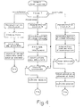
- FIG. 4 is the flow diagram of the analysis task in an embodiment of the network analyzer according to the invention. As indicated above, the analysis can be done according to three possible modes.
- the first is the so-called "transparent” mode.
- This mode is the mode in which the analyzer is located, for example when the 1 key on the keyboard is pressed.
- This mode which is the one implemented during initialization, does not require any particular information.
- the coupler 112 or channel selector is programmed to transmit the data corresponding to the usual data levels.
- a certain number of parameters are sought by the analysis task in the data received for recognition of the standard, protocol, logical channels or magazines present, their formats. , standards, etc.
- the results can be, for example the following: 4 magazines are present; the numbers of these magazines are 01, 02, 04 and OC.
- the procedural byte is 7E. There are 10 lines of data per frame that characterize the source, etc. These results are stored in data tables of the database during the "compilation of results" phase.
- the analysis task in transparent mode is then interruptible and ends if another analysis mode is requested.
- the second possible mode of analysis is a so-called “programmed” mode.
- the automaton assigned to the management of the coupler therefore fulfills a certain number of higher-level functions and discharges the calculation unit from part of the work of interpretation of the different layers of the diffusion protocol.
- the program can be, for example, a program for analyzing the attributes by analyzing the interpretation sequence, or a program for calculating error rates in order to achieve respectively results characteristic of the modalities of the dialogue with the display terminal or characteristics of the link for a given magazine.
- the first step is of course the adequate programming of the channel selector coupler 112 to transmit actually the data of the level to analyze.
- the analysis is synchronized with the standard received so that this standard can be recognized.
- the analyzer task processes the data corresponding to the selected magazine by analyzing the attributes of the various articles (or viewable pages) from the interpretation sequence.
- the results are compiled in the database. A test on the keyboard indicates whether another key has been pressed.
- This analysis mode is interrupted in favor of one of the other two or the analysis continues in the same mode depending on whether another key has been pressed or not.
- This analysis mode is linked to two possible synthesis modes which make it possible to synthesize in the form of an image the attributes of the pages or the errors detected as indicated below.
- the third possible mode is implemented to keep in memory all the data relating to a page of a magazine as they are transmitted before their interpretation by the display terminal.
- the first phase is that of programming the coupler so that it transmits all the data received, as it arrives.
- the analysis task performs synchronization on the selected magazine.
- the data is analyzed for the acquisition of the identification bytes of a given page. If these bytes are not those of the requested page, acquisition continues until the requested page is found. In this case, the data on this page, as received, is transmitted to the page memory (241 in FIG. 3), and the corresponding analysis task is then completed.
- This mode allows, after synthesis, to display the content of a page at the level of its code, before interpretation by the display terminal.
- This analysis mode is linked to a synthesis mode which makes it possible to highlight syntax errors at the level of the code itself as indicated below.
- the first task implemented is the keyboard task Tc, the flow diagram of which is shown in FIG. 5.
- This task recognizes the nature of the order given via the keyboard, from the key pressed, controls the positioning of the analysis task in the corresponding mode and establishes the control codes transmitted to the memory 61 (FIG. 3) for the establishment of the control program for the synthesis task T s .
- the user When the key 1, for example, is pressed, the user requests a transparent analysis, that is to say as indicated above, the analysis of all that is received.
- the keyboard task controls the positioning of the analyzer in transparent mode, mode I, then generates the command codes for the synthesis task, T s .
- the summary task establishes from the data the corresponding video code.
- the keyboard task can be interrupted.
- the keyboard task When the key 2 is pressed, as indicated in the flow diagram of FIG. 5, the user requests the analysis of the interpretation sequence, that is to say as indicated above, the analysis of the attributes of the different pages of a given magazine, the keyboard task sends a response message to the user in response to pressing the key to request the number of the magazine for which the user wishes a video summary.
- the keyboard task checks in the database that the corresponding magazine is present by checking that the requested magazine number exists (otherwise the keyboard task returns to its initial state), then places the analyzer in mode 2, that is to say - say in programmed mode for the analysis of the interpretation sequences.
- the keyboard task then generates command codes corresponding to the synthesis of an image associated with this analysis of the interpretation sequences, mode II synthesis.
- An image can then be reconstructed by the synthesis task from information in the database.
- a grid of squares representing the pages can be established, each type of page recognized by its attributes being colored in a different way, for example red for a cover page, blue for an index page, white for the numbered normal pages.
- the keyboard task When key 3 is pressed, the user requests an error rate analysis; as for the analysis of the sequences of interpretation, the keyboard task requests the number of the magazine concerned and checks that this magazine exists. If yes, the keyboard task controls the positioning of the analysis in programmed mode, mode 2, for the analysis of the error rate, the resulting data being stored in the database. For the synthesis of a video image corresponding to this mode, the keyboard task establishes the command codes for the corresponding synthesis, mode III. For example, a color scale graduating the average error rate per page is defined. The summary task increments an error counter each time a parity error is detected for a given page. The image is then formed from the grid whose squares represent the different pages of the magazine, each square being colored by the color of the scale corresponding to the average error rate measured for the corresponding page.
- the keyboard automaton When key 4 is pressed, the user requests direct viewing of the codes as they are transmitted.
- the keyboard automaton therefore also requests the number of the magazine to be considered, then the page number and verifies each time that the answers given by the user are consistent with the magazines and pages detected previously, during a phase d transparent analysis.
- the keyboard task then ensures the generation of control codes for the synthesis task, in mode IV, for directly viewing the codes of a video image. It is possible to perform additional processing in the synthesis task, for example to perform a video inversion or a color modification on the characters thus entered on which a parity error has been detected. It is also possible to perform a syntactic analysis to verify the consistency of the characters thus entered with the video code used, for example with the antiope code. If syntax errors are detected, the synthesis task affects the corresponding characters of a color change for example.
- the synthesis task T transmits the codes developed to memories 62, 63.
- the display task, T v takes the data in memory and converts it into signals intended to drive the display unit 5 (FIG. 1).
- This task is actually that of the host receiving equipment; it is the module responsible for interpreting the description language for videographic images (ANTIOPE in the example given).
- An additional key on the keyboard can allow the user to view in the normal form a determined videographic image, for example that for which an error rate analysis would have been requested.
- analysis loops for a series of successive pages can be automatically launched.
Landscapes
- Engineering & Computer Science (AREA)
- Health & Medical Sciences (AREA)
- Biomedical Technology (AREA)
- General Health & Medical Sciences (AREA)
- Multimedia (AREA)
- Signal Processing (AREA)
- Testing, Inspecting, Measuring Of Stereoscopic Televisions And Televisions (AREA)
- Computer And Data Communications (AREA)
- Television Systems (AREA)
- Data Exchanges In Wide-Area Networks (AREA)
Applications Claiming Priority (2)
| Application Number | Priority Date | Filing Date | Title |
|---|---|---|---|
| FR8210711A FR2529041A1 (fr) | 1982-06-18 | 1982-06-18 | Procede d'analyse de donnees diffusees, analyseur de reseau mettant en oeuvre un tel procede et equipement de reception utilisant un tel analyseur |
| FR8210711 | 1982-06-18 |
Publications (2)
| Publication Number | Publication Date |
|---|---|
| EP0099276A1 EP0099276A1 (fr) | 1984-01-25 |
| EP0099276B1 true EP0099276B1 (fr) | 1985-12-11 |
Family
ID=9275174
Family Applications (1)
| Application Number | Title | Priority Date | Filing Date |
|---|---|---|---|
| EP83401159A Expired EP0099276B1 (fr) | 1982-06-18 | 1983-06-07 | Procédé d'analyse de données diffusées, analyseur de réseau mettant en oeuvre un tel procédé, et équipement de réception utilisant un tel analyseur |
Country Status (6)
| Country | Link |
|---|---|
| US (1) | US4550407A (en:Method) |
| EP (1) | EP0099276B1 (en:Method) |
| JP (1) | JPS5916479A (en:Method) |
| CA (1) | CA1208759A (en:Method) |
| DE (1) | DE3361483D1 (en:Method) |
| FR (1) | FR2529041A1 (en:Method) |
Families Citing this family (18)
| Publication number | Priority date | Publication date | Assignee | Title |
|---|---|---|---|---|
| US4965825A (en) | 1981-11-03 | 1990-10-23 | The Personalized Mass Media Corporation | Signal processing apparatus and methods |
| US7831204B1 (en) | 1981-11-03 | 2010-11-09 | Personalized Media Communications, Llc | Signal processing apparatus and methods |
| USRE47642E1 (en) | 1981-11-03 | 2019-10-08 | Personalized Media Communications LLC | Signal processing apparatus and methods |
| US4630108A (en) * | 1984-03-26 | 1986-12-16 | A. C. Nielsen Company | Preprogrammed over-the-air marketing research system |
| US7373587B1 (en) * | 1990-06-25 | 2008-05-13 | Barstow David R | Representing sub-events with physical exertion actions |
| US5189630A (en) * | 1991-01-15 | 1993-02-23 | Barstow David R | Method for encoding and broadcasting information about live events using computer pattern matching techniques |
| ES2038923B1 (es) * | 1991-12-19 | 1997-02-16 | Ict Electronics S A | Instrumento portatil para analisis de comunicaciones digitales a dos mbit/s. |
| US5383178A (en) * | 1992-03-26 | 1995-01-17 | Hewlett-Packard Company | Network commentator |
| CA2136567C (en) * | 1994-11-24 | 2001-01-30 | John Charles Maycock | Apparatus and method for remote monitoring of video signals |
| FR2741975B1 (fr) * | 1995-11-30 | 1998-01-09 | Aeg Schneider Automation | Systeme d'entrees-sorties d'automate programmable |
| US5850388A (en) * | 1996-08-02 | 1998-12-15 | Wandel & Goltermann Technologies, Inc. | Protocol analyzer for monitoring digital transmission networks |
| US5850386A (en) * | 1996-11-01 | 1998-12-15 | Wandel & Goltermann Technologies, Inc. | Protocol analyzer for monitoring digital transmission networks |
| US6295092B1 (en) | 1998-07-30 | 2001-09-25 | Cbs Corporation | System for analyzing television programs |
| EP1146749A1 (en) * | 2000-04-07 | 2001-10-17 | Canal+ Technologies Société Anonyme | Apparatus and method for testing applications |
| US7006151B2 (en) * | 2001-04-18 | 2006-02-28 | Sarnoff Corporation | Video streams for closed caption testing and the like |
| US20060075212A1 (en) * | 2002-12-31 | 2006-04-06 | Zeroplus Technology Co., Ltd. | Programmable logic analyzer data analyzing method |
| AU2002364532A1 (en) * | 2002-12-31 | 2004-07-22 | Zeroplus Technology Co., Ltd | Programmable logic analyzer data analyzing method |
| JP4462979B2 (ja) * | 2004-03-26 | 2010-05-12 | 株式会社アドバンテスト | ネットワークアナライザ、伝送トラッキング測定方法、ネットワーク解析方法、プログラムおよび記録媒体 |
Family Cites Families (3)
| Publication number | Priority date | Publication date | Assignee | Title |
|---|---|---|---|---|
| US4052719A (en) * | 1973-07-30 | 1977-10-04 | Independent Broadcasting Authority | Television receiver system having facility for storage and display of character information selected from digitally encoded broadcast transmissions |
| FR2457048A1 (fr) * | 1979-05-16 | 1980-12-12 | Telediffusion Fse | Systeme de videotex muni de moyens de protection contre les erreurs de transmission |
| US4479146A (en) * | 1982-03-08 | 1984-10-23 | Discovision Associates | Vertical code verifier |
-
1982
- 1982-06-18 FR FR8210711A patent/FR2529041A1/fr active Granted
-
1983
- 1983-06-07 EP EP83401159A patent/EP0099276B1/fr not_active Expired
- 1983-06-07 DE DE8383401159T patent/DE3361483D1/de not_active Expired
- 1983-06-14 US US06/504,305 patent/US4550407A/en not_active Expired - Fee Related
- 1983-06-15 CA CA000430449A patent/CA1208759A/en not_active Expired
- 1983-06-16 JP JP58108537A patent/JPS5916479A/ja active Pending
Also Published As
| Publication number | Publication date |
|---|---|
| US4550407A (en) | 1985-10-29 |
| FR2529041B1 (en:Method) | 1984-11-30 |
| EP0099276A1 (fr) | 1984-01-25 |
| FR2529041A1 (fr) | 1983-12-23 |
| JPS5916479A (ja) | 1984-01-27 |
| CA1208759A (en) | 1986-07-29 |
| DE3361483D1 (en) | 1986-01-23 |
Similar Documents
| Publication | Publication Date | Title |
|---|---|---|
| EP0099276B1 (fr) | Procédé d'analyse de données diffusées, analyseur de réseau mettant en oeuvre un tel procédé, et équipement de réception utilisant un tel analyseur | |
| EP0089873B1 (fr) | Dispositif et appareil de test d'équipements électroniques, notamment de télévision | |
| FR2529044A1 (fr) | Procedes et dispositifs de telecommunications visuelles, notamment a l'usage des sourds | |
| EP0702810B1 (fr) | Systeme et procede de dialogue interactif entre un utilisateur et un serveur telematique | |
| EP0089871B1 (fr) | Dispositif de génération de signaux de test d'équipements électroniques | |
| JPH0569356B2 (en:Method) | ||
| CN110609774B (zh) | 一种基于视频图像识别的服务器故障辅助诊断系统及方法 | |
| CN112188259B (zh) | 用于音视频同步测试和校正的方法、装置及电子设备 | |
| CN110458126A (zh) | 一种受电弓状态监测方法及装置 | |
| CN109803096A (zh) | 一种基于脉冲信号的显示方法和系统 | |
| CN106407078A (zh) | 基于信息交互的客户端性能监控装置及方法 | |
| CN109511010A (zh) | 视频处理方法、视频处理装置、电子设备及存储介质 | |
| CN111461253A (zh) | 一种自动化特征提取系统及方法 | |
| CN118093794B (zh) | 一种新型的图形数据转换和可视化方法及系统 | |
| FR2524239A1 (fr) | Equipement de mesure de voies numeriques multiplexees par paquet dans un signal notamment analogique | |
| CN112312207A (zh) | 智能电视终端与移动终端流量打通的方法、装置及设备 | |
| WO1994005119A1 (fr) | Dispositif de controle et de maintenance a distance de reseaux cables | |
| CN113242470B (zh) | 一种应用于外贸营销的视频发布方法及装置 | |
| CN114598901A (zh) | 一种数据分析装置、方法及计算机存储介质 | |
| CN117177012A (zh) | 视频播出监测方法、系统、设备及存储介质 | |
| FR2816793A1 (fr) | Dispositif de traitement d'information multimedia | |
| CN118762067B (zh) | 眼动点映射方法、装置、边缘计算设备和计算机可读存储介质 | |
| FR2850824A1 (fr) | Procede de commande et de conversion de contenu et systeme d'utilisation de contenu | |
| EP0446334B1 (fr) | Dispositif de programmation d'enregistrement par reconnaissance de signaux de reference | |
| CN119728928A (zh) | 基于虚拟终端的可视化监控方法、装置及电子设备 |
Legal Events
| Date | Code | Title | Description |
|---|---|---|---|
| PUAI | Public reference made under article 153(3) epc to a published international application that has entered the european phase |
Free format text: ORIGINAL CODE: 0009012 |
|
| AK | Designated contracting states |
Designated state(s): AT BE CH DE GB IT LI LU NL SE |
|
| 17P | Request for examination filed |
Effective date: 19840609 |
|
| RBV | Designated contracting states (corrected) |
Designated state(s): DE GB NL |
|
| GRAA | (expected) grant |
Free format text: ORIGINAL CODE: 0009210 |
|
| AK | Designated contracting states |
Designated state(s): DE GB NL |
|
| REF | Corresponds to: |
Ref document number: 3361483 Country of ref document: DE Date of ref document: 19860123 |
|
| PGFP | Annual fee paid to national office [announced via postgrant information from national office to epo] |
Ref country code: NL Payment date: 19860630 Year of fee payment: 4 |
|
| PLBE | No opposition filed within time limit |
Free format text: ORIGINAL CODE: 0009261 |
|
| STAA | Information on the status of an ep patent application or granted ep patent |
Free format text: STATUS: NO OPPOSITION FILED WITHIN TIME LIMIT |
|
| 26N | No opposition filed | ||
| PG25 | Lapsed in a contracting state [announced via postgrant information from national office to epo] |
Ref country code: NL Effective date: 19880101 |
|
| NLV4 | Nl: lapsed or anulled due to non-payment of the annual fee | ||
| PG25 | Lapsed in a contracting state [announced via postgrant information from national office to epo] |
Ref country code: DE Effective date: 19880301 |
|
| GBPC | Gb: european patent ceased through non-payment of renewal fee | ||
| PG25 | Lapsed in a contracting state [announced via postgrant information from national office to epo] |
Ref country code: GB Free format text: LAPSE BECAUSE OF NON-PAYMENT OF DUE FEES Effective date: 19881122 |