EP0099276B1 - Method of analysing broadcast data, network analyzer for carrying out such a method, and receiver equipment using such an analyzer - Google Patents
Method of analysing broadcast data, network analyzer for carrying out such a method, and receiver equipment using such an analyzer Download PDFInfo
- Publication number
- EP0099276B1 EP0099276B1 EP83401159A EP83401159A EP0099276B1 EP 0099276 B1 EP0099276 B1 EP 0099276B1 EP 83401159 A EP83401159 A EP 83401159A EP 83401159 A EP83401159 A EP 83401159A EP 0099276 B1 EP0099276 B1 EP 0099276B1
- Authority
- EP
- European Patent Office
- Prior art keywords
- data
- mode
- analyzer
- analyzing
- analysis
- Prior art date
- Legal status (The legal status is an assumption and is not a legal conclusion. Google has not performed a legal analysis and makes no representation as to the accuracy of the status listed.)
- Expired
Links
Images


Classifications
-
- H—ELECTRICITY
- H04—ELECTRIC COMMUNICATION TECHNIQUE
- H04N—PICTORIAL COMMUNICATION, e.g. TELEVISION
- H04N17/00—Diagnosis, testing or measuring for television systems or their details
- H04N17/004—Diagnosis, testing or measuring for television systems or their details for digital television systems
Definitions
- the invention relates to data broadcasting networks and more particularly to a method for analyzing the broadcast data and to a test tool, known as a "network analyzer", implementing such a method, suitable for conventional reception equipment. .
- the broadcasting of the data can be a broadcast by radio, a cable distribution, or a satellite broadcast. Given this diversity and the large number of reception points, it appeared the need for a test tool easy to integrate with the reception equipment, making it possible to carry out link quality measurements from the data received. and monitor the network, viewing the results.
- the subject of the invention is a method for analyzing broadcast data and a network analyzer meeting this need.
- the invention also relates to a network analyzer implementing such a method.
- teletext type data broadcasting networks The purpose of teletext type data broadcasting networks is to display, on a television receiver, texts made up of alphabetic and numeric characters, or simple graphics.
- the corresponding data are transmitted by the transmitters of television networks, either on the same channel as normal television programs and without altering the latter, or by using a special channel.
- Users must have a suitable television set and associated terminal equipment, for demodulation and decoding, from which they can control the appearance on the receiver of a page or of a succession of pages selected from the set of messages transmitted.
- a decoder whose input is coupled to the output S D of the broadcasting channel delivers on its output the broadcast data by separating the useful data from the other data possibly passing through the same broadcast channel.
- the decoder part comprises a demodulation and demultiplexing device 1 which separates the digital data transmitted by the television network from normal programs when these data are transmitted on a channel also used for a normal program .
- the decoder further comprises a digital data processing unit 2 coupled to the output of the demodulation and demultiplexing device 1 by an interface 4.
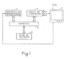
- the equipment comprises a display circuit 3 coupled to the output of the processing unit 2 via interface 4, which directly supplies color video signals, red R, green V, and blue B, controlling the display of data on the tube of a receiver 5.
- the network analyzer according to the invention is included in this terminal equipment to carry out on demand tests, measurements, or monitoring of the data transmitted by the network and received by the equipment; this analyzer directly controls the receiving tube to visualize in a synthetic form the information concerning the digital data acquired, after having subjected them to a processing which puts them in a form suitable for this display by following one of the operating modes recognized by the terminal for the display, ie conventionally the alphamosa ⁇ c mode, the alphageometric mode, or the alphaphotographic mode.
- the processing unit 2 of the team the terminal is programmed with data processing tasks present at the output of the demodulation and demultiplexing device, and tasks of coding the results of these processing tasks for the display of these results, via the circuit of visualization.
- the terminal equipment itself is then a tool for testing data, a tool for monitoring a data broadcasting network, or even a tool for measuring the quality of the level of data broadcasting.
- the network analyzer can operate by following a transparent mode of analysis and display of the data as received by the decoder. This type of network analysis is very useful in particular during the stages of development and fine-tuning of equipment in the distribution chain.
- the analyzer secondly comprises means for entering all the specific parameters of the data signal, and means for synthetic display of all of these parameters. This monitoring is carried out automatically by the use of the terminal control device, for example, a remote control keyboard.
- the network analyzer thirdly comprises measurement means, these measurements being carried out during measurement campaigns.
- the measurement points within the network will be chosen all the more easily to determine the representative sample of the network as each television set equipped with a suitable decoder constitutes a possible measurement point.
- process B react to the user's commands and exploit the information resulting from the analysis by process A to synthesize an image in response transmitted to the receiving tube.
- these two processes can be executed in parallel.
- the computing power of the processing unit 2 may be insufficient to properly carry out these two processes in parallel when the data rate received at the input of the demodulation device 1 is high.
- the means of implementing the network analysis are close to those conventionally used for receiving the transmitted data.
- the demodulation and demultiplexing device 1 comprises a demodulator 11 receiving the composite signal (video + data), and a control signal (window) for selecting the data to be demodulated.
- the output of this demodulator is connected to the input of a demultiplexer 12 performing the separation of the data signals.
- the demodulated and separate signals are then stored in a FIFO memory, 13, from which they are extracted, on command, by the processing unit 2.
- the output of the demultiplexer is coupled via the interface 4 to the bus 21 of the processing unit 2.
- This interface 4 mainly comprises a general data transmission bus 41 and an interface circuit 42.
- the processing unit further comprises a PROM program memory 22 with a capacity of 8K bytes for example , a processing unit MPU 23 constituted by a microprocessor of type 6809 for example, a random access memory RAM, 24, and a circuit for processing commands received from the keyboard 25 coupled to the bus 21.
- the command keyboard can transmit for example infrared IR signals.
- This display circuit comprises a character generator 31, coupled to the general bus 41 of the interface 4. This generator is also coupled to the bus 32 of the display unit, to which is coupled the display unit 33 which supplies the color components R, G, B applied to the tube, depending on the characters to be displayed.
- An extension game memory 34 and a refresh memory 35 are also coupled to the bus 32.
- the display unit 33 receives the frame synchronization signal SYT from the television set; the line synchronization signal SYL of this same television set is received at the control input of a phase loop 36 which supplies the clock signal H to the display unit. This display unit supplies a line signal S L to the phase loop 36.
- this general scheme could be that of a conventional decoder for teletext reception equipment, ANTIOPE for example.
- PROM memory 22 associated with the microprocessor 23 of the processing unit 2 controls the tasks and the transfers indicated schematically in FIG. 3.
- a task distributor 100 coordinates the sequence of the two processes and more precisely the sequence of the tasks which compose them.
- the programmable channel selector, or coupler 112 selects from the data it receives from the demodulator 11 those which must be retained, the selector comprising for this purpose a control input C 112 .
- These selected data present at the output of this selector are transmitted to the memory 13, of capacity 1 K bytes for example.
- the analysis task T A takes these data from the buffer memory 13 and analyzes them according to one of the three possible analysis modes. The flowchart for this analysis task is shown in Figure 4 described below.
- the data resulting from the analysis are transmitted to the RAM memory 24 (FIG. 2) either in a zone called the database 242, or in a zone called the page memory 241. This set of functions forms the process AT.
- process B it is a control keyboard 50 which allows dialogue with the operator and makes it possible to initiate the tasks to be carried out.
- a modulator-demodulator, known as a keyboard modem, 51 coupled to the keyboard ensures the recognition of the data entered by the keyboard or the return of questions requiring an operator response within the framework of an interactive dialogue.
- a keyboard memory 52 is coupled to this modem, this keyboard memory providing the data necessary for the task of managing the keyboard T c .
- This keyboard task is an automatic dialog with the user which transmits to the analysis task (of process A) or to the synthesis task T s (of process B) all the data that they need.
- the synthesis task T processes the data in memory either in the page memory 241, or in the database 242 on command of the operator via the keyboard task T c and a control memory 61.
- This synthesis task Ts provides the resulting data in FIFO memories 62 and 63, of the viewing unit respectively row memory 0 and ANTIOPE memory of 2K bytes according to the usual standard of the viewing system of the ANTIOPE standard, these data being called by a viewing task T v which converts them into color signals directly applicable to the viewing tube.
- the whole is of course managed by a general time base, not shown in FIG. 3.
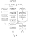
- FIG. 4 is the flow diagram of the analysis task in an embodiment of the network analyzer according to the invention. As indicated above, the analysis can be done according to three possible modes.
- the first is the so-called "transparent” mode.
- This mode is the mode in which the analyzer is located, for example when the 1 key on the keyboard is pressed.
- This mode which is the one implemented during initialization, does not require any particular information.
- the coupler 112 or channel selector is programmed to transmit the data corresponding to the usual data levels.
- a certain number of parameters are sought by the analysis task in the data received for recognition of the standard, protocol, logical channels or magazines present, their formats. , standards, etc.
- the results can be, for example the following: 4 magazines are present; the numbers of these magazines are 01, 02, 04 and OC.
- the procedural byte is 7E. There are 10 lines of data per frame that characterize the source, etc. These results are stored in data tables of the database during the "compilation of results" phase.
- the analysis task in transparent mode is then interruptible and ends if another analysis mode is requested.
- the second possible mode of analysis is a so-called “programmed” mode.
- the automaton assigned to the management of the coupler therefore fulfills a certain number of higher-level functions and discharges the calculation unit from part of the work of interpretation of the different layers of the diffusion protocol.
- the program can be, for example, a program for analyzing the attributes by analyzing the interpretation sequence, or a program for calculating error rates in order to achieve respectively results characteristic of the modalities of the dialogue with the display terminal or characteristics of the link for a given magazine.
- the first step is of course the adequate programming of the channel selector coupler 112 to transmit actually the data of the level to analyze.
- the analysis is synchronized with the standard received so that this standard can be recognized.
- the analyzer task processes the data corresponding to the selected magazine by analyzing the attributes of the various articles (or viewable pages) from the interpretation sequence.
- the results are compiled in the database. A test on the keyboard indicates whether another key has been pressed.
- This analysis mode is interrupted in favor of one of the other two or the analysis continues in the same mode depending on whether another key has been pressed or not.
- This analysis mode is linked to two possible synthesis modes which make it possible to synthesize in the form of an image the attributes of the pages or the errors detected as indicated below.
- the third possible mode is implemented to keep in memory all the data relating to a page of a magazine as they are transmitted before their interpretation by the display terminal.
- the first phase is that of programming the coupler so that it transmits all the data received, as it arrives.
- the analysis task performs synchronization on the selected magazine.
- the data is analyzed for the acquisition of the identification bytes of a given page. If these bytes are not those of the requested page, acquisition continues until the requested page is found. In this case, the data on this page, as received, is transmitted to the page memory (241 in FIG. 3), and the corresponding analysis task is then completed.
- This mode allows, after synthesis, to display the content of a page at the level of its code, before interpretation by the display terminal.
- This analysis mode is linked to a synthesis mode which makes it possible to highlight syntax errors at the level of the code itself as indicated below.
- the first task implemented is the keyboard task Tc, the flow diagram of which is shown in FIG. 5.
- This task recognizes the nature of the order given via the keyboard, from the key pressed, controls the positioning of the analysis task in the corresponding mode and establishes the control codes transmitted to the memory 61 (FIG. 3) for the establishment of the control program for the synthesis task T s .
- the user When the key 1, for example, is pressed, the user requests a transparent analysis, that is to say as indicated above, the analysis of all that is received.
- the keyboard task controls the positioning of the analyzer in transparent mode, mode I, then generates the command codes for the synthesis task, T s .
- the summary task establishes from the data the corresponding video code.
- the keyboard task can be interrupted.
- the keyboard task When the key 2 is pressed, as indicated in the flow diagram of FIG. 5, the user requests the analysis of the interpretation sequence, that is to say as indicated above, the analysis of the attributes of the different pages of a given magazine, the keyboard task sends a response message to the user in response to pressing the key to request the number of the magazine for which the user wishes a video summary.
- the keyboard task checks in the database that the corresponding magazine is present by checking that the requested magazine number exists (otherwise the keyboard task returns to its initial state), then places the analyzer in mode 2, that is to say - say in programmed mode for the analysis of the interpretation sequences.
- the keyboard task then generates command codes corresponding to the synthesis of an image associated with this analysis of the interpretation sequences, mode II synthesis.
- An image can then be reconstructed by the synthesis task from information in the database.
- a grid of squares representing the pages can be established, each type of page recognized by its attributes being colored in a different way, for example red for a cover page, blue for an index page, white for the numbered normal pages.
- the keyboard task When key 3 is pressed, the user requests an error rate analysis; as for the analysis of the sequences of interpretation, the keyboard task requests the number of the magazine concerned and checks that this magazine exists. If yes, the keyboard task controls the positioning of the analysis in programmed mode, mode 2, for the analysis of the error rate, the resulting data being stored in the database. For the synthesis of a video image corresponding to this mode, the keyboard task establishes the command codes for the corresponding synthesis, mode III. For example, a color scale graduating the average error rate per page is defined. The summary task increments an error counter each time a parity error is detected for a given page. The image is then formed from the grid whose squares represent the different pages of the magazine, each square being colored by the color of the scale corresponding to the average error rate measured for the corresponding page.
- the keyboard automaton When key 4 is pressed, the user requests direct viewing of the codes as they are transmitted.
- the keyboard automaton therefore also requests the number of the magazine to be considered, then the page number and verifies each time that the answers given by the user are consistent with the magazines and pages detected previously, during a phase d transparent analysis.
- the keyboard task then ensures the generation of control codes for the synthesis task, in mode IV, for directly viewing the codes of a video image. It is possible to perform additional processing in the synthesis task, for example to perform a video inversion or a color modification on the characters thus entered on which a parity error has been detected. It is also possible to perform a syntactic analysis to verify the consistency of the characters thus entered with the video code used, for example with the antiope code. If syntax errors are detected, the synthesis task affects the corresponding characters of a color change for example.
- the synthesis task T transmits the codes developed to memories 62, 63.
- the display task, T v takes the data in memory and converts it into signals intended to drive the display unit 5 (FIG. 1).
- This task is actually that of the host receiving equipment; it is the module responsible for interpreting the description language for videographic images (ANTIOPE in the example given).
- An additional key on the keyboard can allow the user to view in the normal form a determined videographic image, for example that for which an error rate analysis would have been requested.
- analysis loops for a series of successive pages can be automatically launched.
Description
L'invention se rapporte aux réseaux de diffusion de données et plus particulièrement à un procédé d'analyse des données diffusées et à un outil de test, dit « analyseur de réseau •, mettant en oeuvre un tel procédé, adapté aux équipements classiques de réception.The invention relates to data broadcasting networks and more particularly to a method for analyzing the broadcast data and to a test tool, known as a "network analyzer", implementing such a method, suitable for conventional reception equipment. .
Dans un réseau de diffusion de données, réseau de télétexte « ANTIOPE » par exemple, la diffusion des données peut être une diffusion par voie hertzienne, une distribution par câble, ou une diffusion par satellite. Compte tenu de cette diversité et du grand nombre de points de réception, il est apparu le besoin d'un outil de test facile à intégrer à l'équipement de réception, permettant d'effectuer des mesures de qualité de liaison à partir des données reçues et de surveiller le réseau, en visualisant les résultats.In a data broadcasting network, for example the “ANTIOPE” teletext network, the broadcasting of the data can be a broadcast by radio, a cable distribution, or a satellite broadcast. Given this diversity and the large number of reception points, it appeared the need for a test tool easy to integrate with the reception equipment, making it possible to carry out link quality measurements from the data received. and monitor the network, viewing the results.
L'invention a pour objet un procédé d'analyse de données diffusées et un analyseur de réseau répondant à ce besoin.The subject of the invention is a method for analyzing broadcast data and a network analyzer meeting this need.
Suivant l'invention, un procédé d'analyse de données diffusées, codées suivant une structure organisée en plusieurs niveaux et destinées à être interprétées par un terminal de visualisation vidéographique, est caractérisé en ce que :
- - dans une première phase, l'opérateur commande la sélection des données d'un niveau déterminé et les analyse suivant l'un ou l'autre de plusieurs modes d'analyse, soit ,un mode dit transparent, pour extraire les paramètres relatifs aux caractéristiques de la transmission présents dans les données transmises, soit un mode, dit programmé, pour mesurer des paramètres relatifs aux conditions de la transmission, soit un mode, dit de capture, pour mettre en mémoire ces données elles-mêmes avant tout traitement ou interprétation ;
- - dans une seconde phase, les résultats de l'analyse sont codés en suivant la norme du terminal de visualisation vidéographique, sous forme d'images synthétiques caractérisant les paramètres extraits ou mesurés, ou les données mises en mémoire avant interprétation ;
- - et dans une dernière phase les résultats de l'analyse, codés suivant cette norme vidéographique, sont interprétés et visualisés.
- - in a first phase, the operator controls the selection of the data of a determined level and analyzes it according to one or the other of several analysis modes, that is, a so-called transparent mode, to extract the parameters relating to the characteristics of the transmission present in the transmitted data, either a so-called programmed mode for measuring parameters relating to the conditions of the transmission, or a so-called capture mode for storing these data themselves before any processing or interpretation ;
- - in a second phase, the results of the analysis are coded according to the standard of the video display terminal, in the form of synthetic images characterizing the parameters extracted or measured, or the data stored in memory before interpretation;
- - and in a last phase the results of the analysis, coded according to this video standard, are interpreted and displayed.
L'invention a également pour objet un analyseur de réseau mettant en oeuvre un tel procédé.The invention also relates to a network analyzer implementing such a method.
L'invention sera mieux comprise et d'autres caractéristiques apparaîtront à l'aide de la description qui suit en référence aux figures annexées :
- la figure 1 est un schéma d'organisation général d'un équipement de réception pour un réseau de diffusion de données ;
- la figure 2 est un schéma plus détaillé d'un mode de réalisation de l'équipement de réception dans lequel est prévu l'analyseur de réseau ;
- la figure 3 représente un schéma fonctionnel des tâches réalisées par l'analyseur de réseau ;
- la figure 4 est l'organigramme des fonctions d'analyse de cet analyseur ;
- la figure 5 est l'organigramme de la tâche clavier de cet analyseur.
- FIG. 1 is a general organization diagram of reception equipment for a data broadcasting network;
- FIG. 2 is a more detailed diagram of an embodiment of the reception equipment in which the network analyzer is provided;
- FIG. 3 represents a functional diagram of the tasks performed by the network analyzer;
- FIG. 4 is the flow chart of the analysis functions of this analyzer;
- FIG. 5 is the flow diagram of the keyboard task of this analyzer.
Les réseaux de diffusion de données du type télétexte ont pour objet de permettre la visualisation, sur un récepteur de télévision, de textes constitués de caractères alphabétiques et numériques, ou de graphismes simples. Les données correspondantes sont transmises par les émetteurs des réseaux de télévision, soit sur le même canal que les programmes normaux de télévision et sans altérer ces derniers, soit en recourant à un canal spécial. Les utilisateurs doivent disposer d'un téléviseur adapté et d'un équipement terminal associé, pour la démodulation et le décodage, à partir duquel ils peuvent commander l'apparition sur le récepteur d'une page ou d'une succession de pages sélectionnées dans l'ensemble des messages transmis.The purpose of teletext type data broadcasting networks is to display, on a television receiver, texts made up of alphabetic and numeric characters, or simple graphics. The corresponding data are transmitted by the transmitters of television networks, either on the same channel as normal television programs and without altering the latter, or by using a special channel. Users must have a suitable television set and associated terminal equipment, for demodulation and decoding, from which they can control the appearance on the receiver of a page or of a succession of pages selected from the set of messages transmitted.
La structure générale d'un équipement terminal d'un réseau de diffusion de données du type télétexte où les données sont transmises par paquets dans un signal multiplexé contenant ces données et le signal vidéo classique, est donnée ci-après en référence à la figure 1.The general structure of a terminal equipment of a teletext type data broadcasting network where the data is transmitted in packets in a multiplexed signal containing this data and the conventional video signal, is given below with reference to FIG. 1 .
Un décodeur dont l'entrée est couplée à la sortie SD de la voie de diffusion délivre sur sa sortie les données diffusées en séparant les données utiles des autres données transitant éventuellement par la même voie de diffusion.A decoder whose input is coupled to the output S D of the broadcasting channel delivers on its output the broadcast data by separating the useful data from the other data possibly passing through the same broadcast channel.
Dans un équipement terminal pour un réseau de télétexte, la partie décodeur comporte un dispositif de démodulation et de démultiplexage 1 qui sépare les données numériques transmises par le réseau de télévision des programmes normaux lorsque ces données sont transmises sur un canal également utilisé pour un programme normal. Le décodeur comporte en outre une unité de traitement des données numériques 2 couplée à la sortie du dispositif de démodulation et de démultiplexage 1 par une interface 4. Enfin l'équipement comporte un circuit de visualisation 3 couplé à la sortie de l'unité de traitement 2 par l'interface 4, qui fournit directement les signaux vidéo de couleur, rouge R, vert V, et bleu B, commandant l'affichage des données sur le tube d'un récepteur 5.In terminal equipment for a teletext network, the decoder part comprises a demodulation and
L'analyseur de réseau suivant l'invention est inclus dans cet équipement terminal pour réaliser à la demande des tests, des mesures, ou une surveillance des données transmises par le réseau et reçues par l'équipement ; cet analyseur commande directement le tube récepteur pour visualiser sous une forme synthétique les informations concernant les données numériques acquises, après leur avoir fait subir un traitement qui les met dans une forme adaptée à cet affichage en suivant l'un des modes de fonctionnement reconnus par le terminal pour l'affichage, c'est-à-dire classiquement le mode alphamosaï- que, le mode alphagéométrique, ou le mode alphaphotographique.The network analyzer according to the invention is included in this terminal equipment to carry out on demand tests, measurements, or monitoring of the data transmitted by the network and received by the equipment; this analyzer directly controls the receiving tube to visualize in a synthetic form the information concerning the digital data acquired, after having subjected them to a processing which puts them in a form suitable for this display by following one of the operating modes recognized by the terminal for the display, ie conventionally the alphamosaïc mode, the alphageometric mode, or the alphaphotographic mode.
A cet effet, l'unité de traitement 2 de l'équipement terminal est programmée avec des tâches de traitement des données présentes à la sortie du dispositif de démodulation et de démultiplexage, et des tâches de codage des résultats de ces tâches de traitement pour l'affichage de ces résultats, par l'intermédiaire du circuit de visualisation.To this end, the
L'équipement terminal lui-même est alors un outil de test des données, un outil de surveillance d'un réseau de diffusion de données, ou encore un outil de mesure de la qualité du niveau de diffusion de données.The terminal equipment itself is then a tool for testing data, a tool for monitoring a data broadcasting network, or even a tool for measuring the quality of the level of data broadcasting.
En ce qui concerne l'aspect outil de test du matériel, l'analyseur de réseau peut fonctionner en suivant un mode transparent d'analyse et d'affichage des données telles qu'elles sont reçues par le décodeur. Ce type d'analyse de réseau est très utile en particulier lors des étapes de développement et de mise au point d'un équipement de la chaîne de diffusion.With regard to the hardware test tool aspect, the network analyzer can operate by following a transparent mode of analysis and display of the data as received by the decoder. This type of network analysis is very useful in particular during the stages of development and fine-tuning of equipment in the distribution chain.
Pour la surveillance d'un réseau, l'analyseur comporte en second lieu des moyens de saisie de tous les paramètres spécifiques du signal de données, et des moyens de visualisation synthétique de l'ensemble de ces paramètres. Cette surveillance est réalisée automatiquement par l'utilisation du dispositif de commande du terminal, par exemple, un clavier de télécommande.For monitoring a network, the analyzer secondly comprises means for entering all the specific parameters of the data signal, and means for synthetic display of all of these parameters. This monitoring is carried out automatically by the use of the terminal control device, for example, a remote control keyboard.
Enfin, pour la mesure de la qualité du niveau de diffusion de données, l'analyseur de réseau comporte en troisième lieu des moyens de mesure, ces mesures étant réalisées au cours de campagnes de mesures. Les points de mesure à l'intérieur du réseau seront choisis d'autant plus facilement pour déterminer l'échantillon représentatif du réseau que chaque téléviseur équipé d'un décodeur adapté constitue un point de mesure possible.Finally, for measuring the quality of the level of data dissemination, the network analyzer thirdly comprises measurement means, these measurements being carried out during measurement campaigns. The measurement points within the network will be chosen all the more easily to determine the representative sample of the network as each television set equipped with a suitable decoder constitutes a possible measurement point.
La description qui suit donne un exemple de procédé d'analyse de données diffusées précisant quelques-unes des possibilités offertes par un tel équipement convenablement programmé.The following description gives an example of a method for analyzing disseminated data specifying some of the possibilities offered by such suitably programmed equipment.
D'un point de vue fonctionnel les tâches de l'analyseur de réseau peuvent être regroupées en deux groupes de tâches :
- Les premières, groupées en un processus qui sera dit « processus A •, réalisent les fonctions d'analyse proprement dite et de gestion de l'interface avec le circuit de réception.
- The first, grouped into a process which will be called "process A •, perform the analysis functions proper and manage the interface with the reception circuit.
Les secondes, groupées en un processus qui sera dit « processus B •, réagissent aux commandes de l'utilisateur et exploitent les informations issues de l'analyse par le processus A pour synthétiser une image en réponse transmise au tube récepteur.The seconds, grouped into a process which will be called “process B •, react to the user's commands and exploit the information resulting from the analysis by process A to synthesize an image in response transmitted to the receiving tube.
Fonctionnellement, ces deux processus peuvent être exécutés en parallèle. Mais la puissance de calcul de l'unité de traitement 2 peut être insuffisante pour réaliser convenablement ces deux processus en parallèle lorsque le débit d'informations reçu à l'entrée du dispositif de démodulation 1 est élevé.Functionally, these two processes can be executed in parallel. However, the computing power of the
La description qui suit concerne une solution dans laquelle ces deux processus sont exécutés séquentiellement ; ce qui permet de conserver une certaine indépendance entre les traitements des données reçues et leurs débits. Cette description n'est nullement limitative.The following description relates to a solution in which these two processes are executed sequentially; which allows to maintain a certain independence between the processing of the data received and their data rates. This description is in no way limiting.
Les moyens de mise en oeuvre de l'analyse de réseau sont voisins de ceux utilisés classiquement pour la réception des données transmises.The means of implementing the network analysis are close to those conventionally used for receiving the transmitted data.
La figure 2 représente en détails ces moyens. Le dispositif de démodulation et de démultiplexage 1 comporte un démodulateur 11 recevant le signal composite (vidéo + données), et un signal de commande (fenêtre) pour la sélection des données à démoduler. La sortie de ce démodulateur est reliée à l'entrée d'un démultiplexeur 12 effectuant la séparation des signaux de données. Les signaux démodulés et séparés sont alors mis en mémoire dans une mémoire FIFO, 13, de laquelle ils sont extraits, sur commande, par l'unité de traitement 2. Pour cela, la sortie du démultiplexeur est couplée via l'interface 4 au bus 21 de l'unité de traitement 2. Cette interface 4 comporte principalement un bus général de transmission de données 41 et un circuit d'interface 42. L'unité de traitement comporte en outre une mémoire de programme PROM 22 de capacité 8K octets par exemple, une unité de traitement MPU 23 constituée par un microprocesseur de type 6809 par exemple, une mémoire à accès aléatoire RAM, 24, et un circuit de traitement des commandes reçues du clavier 25 couplés au bus 21. Le clavier de commande peut émettre par exemple des signaux infra-rouge IR.Figure 2 shows in detail these means. The demodulation and
Pour l'affichage, les éléments de l'unité de traitement interviennent via l'interface 4 et le circuit de visualisation 3. Ce circuit de visualisation comporte un générateur de caractères 31, couplé au bus général 41 de l'interface 4. Ce générateur est par ailleurs couplé au bus 32 de l'unité de visualisation, auquel est couplée l'unité de visualisation 33 qui fournit les composantes de couleurs R, V, B appliquées au tube, fonction des caractères à afficher. Une mémoire jeu d'extension 34 et une mémoire de rafraîchissement 35 sont également couplées au bus 32. L'unité de visualisation 33 reçoit le signal de synchronisation trame SYT du téléviseur ; le signal de synchronisation ligne SYL de ce même téléviseur est reçu à l'entrée de commande d'une boucle de phase 36 qui fournit le signal d'horloge H à l'unité de visualisation. Cette unité de visualisation fournit un signal de ligne SL à la boucle de phase 36.For the display, the elements of the processing unit intervene via the
Sans autre précision sur les différents sous- ensembles, ce schéma général pourrait être celui d'un décodeur classique pour un équipement de réception de télétexte, ANTIOPE par exemple.Without further details on the different subsets, this general scheme could be that of a conventional decoder for teletext reception equipment, ANTIOPE for example.
Ce terminal devient un analyseur de données diffusées si l'on précise que :
- - la mémoire de
programme 22 comporte un certain nombre de programmes de traitement particuliers destinés à prendre en compte des demandes de traitement lors d'un dialogue avec l'utilisateur dans le cadre d'une procédure de test, interactive ou non, à analyser les données diffusées, à effectuer une synthèse des résultats de cette analyse ; - - la mémoire RAM, 24, a une capacité et une organisation telles qu'elle peut contenir les données nécessaires à ces traitements particuliers ;
- -
le démultiplexeur 12 qui normalement ne transmet que les informations utiles comporte un coupleur programmable pour transmettre les données correspondant à l'un ou l'autre des niveaux de la norme de diffusion de données susceptibles d'être analysés, par exemple les séquences d'interprétation lorsque le traitement consiste à vérifier ces séquences ; - - le circuit de visualisation comporte un automate de visualisation qui permet d'afficher dans une forme conventionnelle les résultats de tests obtenus après synthèse.
- the
program memory 22 includes a certain number of particular processing programs intended to take into account processing requests during a dialogue with the user within the framework of a test procedure, interactive or not, to analyze the disseminated data, to synthesize the results of this analysis; - - the RAM memory, 24, has a capacity and a organization as it may contain the data necessary for these particular treatments;
- the
demultiplexer 12 which normally only transmits useful information comprises a programmable coupler for transmitting the data corresponding to one or the other of the levels of the data dissemination standard capable of being analyzed, for example the sequences of interpretation when processing consists of verifying these sequences; - the display circuit comprises a display automaton which makes it possible to display in a conventional form the test results obtained after synthesis.
Avec un tel équipement, l'utilisateur peut accéder, via le clavier de commande à trois types de services :
- Une analyse de la procédure et du protocole de transmission.
- An analysis of the transmission procedure and protocol.
Des mesures de taux d'erreur.Error rate measurements.
Un contrôle du réseau.Network control.
Pour cela la mémoire PROM 22 associée au microprocesseur 23 de l'unité de traitement 2 commande les tâches et les transferts indiqués schématiquement sur la figure 3.For this, the
Un distributeur de tâches 100 coordonne l'enchaînement des deux processus et plus précisément l'enchaînement des tâches qui les composent.A
Dans le processus « A », le sélecteur de voies programmable, ou coupleur 112 sélectionne parmi les données qu'il reçoit du démodulateur 11 celles qui doivent être retenues, le sélecteur comportant à cet effet une entrée de commande C112. Ces données sélectionnées présentes à la sortie de ce sélecteur sont transmises à la mémoire 13, de capacité 1 K octets par exemple. La tâche d'analyse TA, prend ces données dans la mémoire tampon 13 et les analyse suivant l'un des trois modes d'analyse possibles. L'organigramme de cette tâche d'analyse est représenté sur la figure 4 décrite ci-après. Selon le mode envisagé, les données résultant de l'analyse sont transmises à la mémoire RAM 24 (figure 2) soit dans une zone dite base de données 242, soit dans une zone dite mémoire de pages 241. Cet ensemble de fonctions forme le processus A.In process "A", the programmable channel selector, or
Dans le processus B, c'est un clavier de commande 50 qui permet le dialogue avec l'opérateur et permet d'engager les tâches à réaliser. Un modulateur-démodulateur, dit modem clavier, 51 couplé au clavier assure la reconnaissance des données introduites par le clavier ou le retour de questions nécessitant une réponse de l'opérateur dans le cadre d'un dialogue interactif. Une mémoire clavier 52 est couplée à ce modem, cette mémoire clavier fournissant les données nécessaires à la tâche de gestion du clavier Tc. Cette tâche clavier est un automate de dialogue avec l'utilisateur qui transmet à la tâche d'analyse (du processus A) ou à la tâche de synthèse Ts (du processus B) l'ensemble des données qui leur sont nécessaires. La tâche de synthèse T traite les données en mémoire soit dans la mémoire de page 241, soit dans la base de données 242 sur commande de l'opérateur via la tâche clavier Tc et une mémoire de commande 61. Cette tâche de synthèse Ts fournit les données résultantes à des mémoires FIFO 62 et 63, de l'unité de visualisation respectivement mémoire de rangée 0 et mémoire ANTIOPE de 2K octets suivant la norme habituelle du système de visualisation de la norme ANTIOPE, ces données étant appelées par une tâche de visualisation Tv qui les convertit en signaux de couleur directement applicables au tube de visualisation.In process B, it is a
L'ensemble est bien sûr géré par une base de temps générale, non représentée sur la figure 3.The whole is of course managed by a general time base, not shown in FIG. 3.
La figure 4 est l'organigramme de la tâche d'analyse dans un mode de réalisation de l'analyseur de réseau suivant l'invention. Comme indiqué ci-dessus, l'analyse peut être faite suivant trois modes possibles.FIG. 4 is the flow diagram of the analysis task in an embodiment of the network analyzer according to the invention. As indicated above, the analysis can be done according to three possible modes.
Le premier est le mode dit « transparent • . C'est le mode dans lequel se trouve l'analyseur lorsque par exemple la touche 1 du clavier est enfoncée. Ce mode, qui est celui mis en oeuvre lors de l'initialisation, ne nécessite pas d'information particulière. Dans ce mode, le coupleur 112 ou sélecteur de voies est programmé pour transmettre les données correspondant aux niveaux de données habituels. Après la phase de programmation du coupleur et la phase acquisition des données, un certain nombre de paramètres sont recherchés par la tâche d'analyse dans les données reçues pour la reconnaissance du standard, du protocole, des voies logiques ou magazines présents, de leurs formats, normes, etc. Les résultats peuvent être, par exemple les suivants : 4 magazines sont présents ; les numéros de ces magazines sont 01, 02, 04 et OC. L'octet de procédure est 7E. Il y a 10 lignes de données par trame qui caractérisent la source, etc. Ces résultats sont rangés dans des tables de données de la base de données durant la phase « compilation des résultats •. La tâche analyse en mode transparent est alors interruptible et se termine si un autre mode d'analyse est demandé.The first is the so-called "transparent" mode. This is the mode in which the analyzer is located, for example when the 1 key on the keyboard is pressed. This mode, which is the one implemented during initialization, does not require any particular information. In this mode, the
Le second mode possible d'analyse est un mode dit « programmé •. Dans ce mode au lieu de prendre en compte toutes les données et d'analyser un certain nombre de caractères automatiquement, seulement certaines données sont considérées et traitées suivant un programme défini. L'automate affecté à la gestion du coupleur remplit donc un certain nombre de fonctions de niveau supérieur et décharge l'unité de calcul d'une partie du travail d'interprétation des différentes couches du protocoie de diffusion. Le programme peut être par exemple un programme d'analyse des attributs par analyse de la séquence d'interprétation, ou un programme de calcul des taux d'erreurs pour aboutir respectivement à des résultats caractéristiques des modalités du dialogue avec le terminal de visualisation ou caractéristiques de la liaison pour un magazine donné. Dans ce mode, la première étape est bien entendu la programmation adéquate du coupleur sélecteur de voies 112 pour transmettre effectivement les données du niveau à analyser. Dans une deuxième étape, une synchronisation de l'analyse sur le standard reçu est réalisée de façon que ce standard puisse être reconnu. Lorsque cette synchronisation est réalisée, la tâche analyseur traite les données correspondant au magazine sélectionné en analysant les attributs des différents articles (ou pages visualisables) à partir de la séquence d'interprétation. Exemple : type de page : couverture, page de garde, etc. ; nombre de pages ; numéro de page...- ; ou en calculant par exemple des taux d'erreurs par page. Dans la phase suivante les résultats sont compilés dans la base de données. Un test sur le clavier permet de savoir si une autre touche a été enfoncée. Ce mode d'analyse est interrompu au profit de l'un des deux autres ou l'analyse se poursuit suivant le même mode suivant qu'une autre touche a été enfoncée ou pas. Ce mode d'analyse est lié à deux modes de synthèse possibles qui permettent de synthétiser sous forme d'une image les attributs des pages ou les erreurs détectées comme indiqué ci-après.The second possible mode of analysis is a so-called “programmed” mode. In this mode, instead of taking all the data into account and analyzing a certain number of characters automatically, only certain data are considered and processed according to a defined program. The automaton assigned to the management of the coupler therefore fulfills a certain number of higher-level functions and discharges the calculation unit from part of the work of interpretation of the different layers of the diffusion protocol. The program can be, for example, a program for analyzing the attributes by analyzing the interpretation sequence, or a program for calculating error rates in order to achieve respectively results characteristic of the modalities of the dialogue with the display terminal or characteristics of the link for a given magazine. In this mode, the first step is of course the adequate programming of the
Le troisième mode possible dit mode « capture est mis en oeuvre pour conserver en mémoire toutes les données relatives à une page d'un magazine telles qu'elles sont transmises avant leur interprétation par le terminal de visualisation. Pour ce mode comme pour les précédents, la première phase est celle de la programmation du coupleur afin qu'il transmette toutes les données reçues, comme elles arrivent. Dans une deuxième phase la tâche analyse réalise la synchronisation sur le magazine sélectionné. Lorsque cette synchronisation est réalisée, les données sont analysées pour l'acquisition des octets d'identification d'une page donnée. Si ces octets ne sont pas ceux de la page demandée l'acquisition se poursuit jusqu'à ce que la page demandée soit trouvée. Dans ce cas, les données de cette page, telles qu'elles sont reçues, sont transmises à la mémoire de page (241 sur la figure 3), et la tâche analyse correspondante est alors terminée. Ce mode permet après synthèse de visualiser le contenu d'une page au niveau de son code, avant interprétation par le terminal de visualisation. Ce mode d'analyse est lié à un mode de synthèse qui permet de mettre en évidence les erreurs de syntaxe au niveau du code proprement dit comme indiqué ci-après.The third possible mode known as “capture mode” is implemented to keep in memory all the data relating to a page of a magazine as they are transmitted before their interpretation by the display terminal. For this mode as for the previous ones, the first phase is that of programming the coupler so that it transmits all the data received, as it arrives. In a second phase, the analysis task performs synchronization on the selected magazine. When this synchronization is carried out, the data is analyzed for the acquisition of the identification bytes of a given page. If these bytes are not those of the requested page, acquisition continues until the requested page is found. In this case, the data on this page, as received, is transmitted to the page memory (241 in FIG. 3), and the corresponding analysis task is then completed. This mode allows, after synthesis, to display the content of a page at the level of its code, before interpretation by the display terminal. This analysis mode is linked to a synthesis mode which makes it possible to highlight syntax errors at the level of the code itself as indicated below.
Dans le processus B la première tâche mise en oeuvre est la tâche clavier Tc dont l'organigramme est représenté sur la figure 5. Cette tâche reconnaît la nature de l'ordre donné par l'intermédiaire du clavier, à partir de la touche enfoncée, commande le positionnement de la tâche analyse sur le mode correspondant et établit les codes de commande transmis à la mémoire 61 (figure 3) pour l'établissement du programme de commande de la tâche de synthèse Ts.In process B, the first task implemented is the keyboard task Tc, the flow diagram of which is shown in FIG. 5. This task recognizes the nature of the order given via the keyboard, from the key pressed, controls the positioning of the analysis task in the corresponding mode and establishes the control codes transmitted to the memory 61 (FIG. 3) for the establishment of the control program for the synthesis task T s .
Lorsque la touche 1, par exemple, est enfoncée, l'utilisateur demande une analyse transparente, c'est-à-dire comme indiqué ci-dessus l'analyse de tout ce qui est reçu. La tâche clavier commande le positionnement de l'analyseur en mode transparent, mode I, puis génère les codes de commande pour la tâche de synthèse, Ts. Cette tâche de synthèse dans ce mode « dit mode 1 ≫ consiste à lire dans les tables de la base de données 242 (figure 3) les données qui y ont été stockées et à les coder pour former une image de ces données en suivant le code de description de l'image vidéographique classique. A titre d'exemple, il est possible d'affecter à chaque magazine possible un carré dans une grille formée dans l'image et de colorer ces carrés lorsque les magazines correspondants sont présents. La tâche synthèse établit à partir des données le code vidéographique correspondant.When the
Lorsque la touche 1 n'est plus enfoncée, la tâche clavier peut être interrompue.When the 1 key is no longer pressed, the keyboard task can be interrupted.
Lorsque la touche 2 est enfoncée, comme indiqué dans l'organigramme de la figure 5, l'utilisateur demande l'analyse de la séquence d'interprétation, c'est-à-dire comme indiqué ci-dessus, l'analyse des attributs des différentes pages d'un magazine donné, la tâche clavier émet en réponse à l'enfoncement de la touche un message en retour vers l'utilisateur pour demander le numéro du magazine pour lequel l'utilisateur souhaite une synthèse vidéographique. La tâche clavier contrôle dans la base de données que le magazine correspondant est bien présent en vérifiant que le numéro de magazine demandé existe (sinon la tâche clavier reprend son état initial), puis positionne l'analyseur en mode 2, c'est-à-dire en mode programmé pour l'analyse des séquences d'interprétation. La tâche clavier génère alors des codes de commande correspondant à la synthèse d'une image associée à cette analyse des séquences d'interprétation, synthèse mode II. Une image peut alors être reconstituée par la tâche de synthèse à partir des informations dans la base de données. Par exemple, une grille de carrés représentant les pages peut être établie, chaque type de page reconnu par ses attributs étant coloré d'une manière différente, par exemple rouge pour une page de couverture, bleu pour une page d'index, blanc pour les pages normales numérotées.When the
Lorsque la touche 3 est enfoncée, l'utilisateur demande une analyse de taux d'erreur ; comme pour l'analyse des séquences d'interprétation, la tâche clavier demande le numéro du magazine concerné et vérifie que ce magazine existe bien. Si oui, la tâche clavier commande le positionnement de l'analyse en mode programmé, mode 2, pour l'analyse du taux d'erreur, les données résultantes étant mises en mémoire dans la base de données. Pour la synthèse d'une image vidéographique correspondant à ce mode, la-tâche clavier établit les codes de commande pour la synthèse correspondante, mode III. Par exemple, une échelle colorimétrique graduant le taux moyen d'erreur par page est définie. La tâche synthèse incrémente un compteur d'erreur chaque fois qu'une erreur de parité est détectée pour une page déterminée. L'image est alors formée à partir de la grille dont les carrés représentent les différentes pages du magazine, chaque carré étant coloré par la couleur de l'échelle correspondant au taux d'erreur moyen mesuré pour la page correspondante.When key 3 is pressed, the user requests an error rate analysis; as for the analysis of the sequences of interpretation, the keyboard task requests the number of the magazine concerned and checks that this magazine exists. If yes, the keyboard task controls the positioning of the analysis in programmed mode,
Lorsque la touche 4 est enfoncée, l'utilisateur demande la visualisation directe des codes tels qu'ils sont transmis. L'automate du clavier demande donc également le numéro du magazine à considérer, puis le numéro de la page et vérifie à chaque fois que les réponses données par l'utilisateur sont cohérentes avec les magazines et pages détectés précédemment, lors d'une phase d'analyse transparente. La tâche clavier assure alors la génération des codes de commande pour la tâche synthèse, en mode IV, pour regarder directement les codes d'une image vidéographique. Il est possible de réaliser un traitement supplémentaire dans la tâche synthèse, par exemple pour effectuer une inversion vidéo ou une modification de couleur sur les caractères ainsi saisis sur lesquels une erreur de parité a été détectée. Il est également possible de réaliser une analyse syntaxique pour vérifier la cohérence des caractères ainsi saisis avec le code vidéographique utilisé, par exemple avec le code antiope. Si des erreurs de syntaxe sont détectées, la tâche synthèse affecte les caractères correspondants d'un changement de couleur par exemple.When key 4 is pressed, the user requests direct viewing of the codes as they are transmitted. The keyboard automaton therefore also requests the number of the magazine to be considered, then the page number and verifies each time that the answers given by the user are consistent with the magazines and pages detected previously, during a phase d transparent analysis. The keyboard task then ensures the generation of control codes for the synthesis task, in mode IV, for directly viewing the codes of a video image. It is possible to perform additional processing in the synthesis task, for example to perform a video inversion or a color modification on the characters thus entered on which a parity error has been detected. It is also possible to perform a syntactic analysis to verify the consistency of the characters thus entered with the video code used, for example with the antiope code. If syntax errors are detected, the synthesis task affects the corresponding characters of a color change for example.
La tâche de synthèse T transmet les codes élaborés aux mémoires 62, 63.The synthesis task T transmits the codes developed to
La tâche visualisation, Tv, prend les données en mémoire et les convertit en signaux destinés à piloter l'organe de visualisation 5 (figure 1). Cette tâche est en fait celle de l'équipement de réception hôte ; c'est le module chargé d'interpréter le langage de description des images vidéographi- ques (ANTIOPE dans l'exemple donné). Une touche supplémentaire sur le clavier, peut permettre à l'utilisateur la visualisation sous la forme normale d'une image vidéographique déterminée, par exemple celle pour laquelle aurait été demandée une anlyse de taux d'erreur.The display task, T v , takes the data in memory and converts it into signals intended to drive the display unit 5 (FIG. 1). This task is actually that of the host receiving equipment; it is the module responsible for interpreting the description language for videographic images (ANTIOPE in the example given). An additional key on the keyboard can allow the user to view in the normal form a determined videographic image, for example that for which an error rate analysis would have been requested.
L'invention n'est pas limitée au mode de réalisation précisément décrit ci-dessus qui peut faire l'objet de variantes. En particulier, des boucles d'analyse pour une suite de pages successives peuvent être automatiquement lancées. Par exemple, un index : « auto a une valeur 1 pour un rafraîchissement en temps réel des données calculées, et une valeur n pour un rafraîchissement toutes les n pages successives transmises d'un même article (une page donnée d'un magazine).The invention is not limited to the embodiment precisely described above which can be subject to variants. In particular, analysis loops for a series of successive pages can be automatically launched. For example, an index: “auto has a
Par ailleurs, d'autres traitements peuvent être effectués sur les données reçues et les données caractéristiques captées ou calculées lors de ces traitements peuvent être visualisées suivant un code quelconque pourvu que des images synthétiques de ces données soient formées sur le terminal de visualisation.Furthermore, other processing can be carried out on the data received and the characteristic data captured or calculated during these processing can be displayed according to any code provided that synthetic images of this data are formed on the display terminal.
Claims (10)
Applications Claiming Priority (2)
| Application Number | Priority Date | Filing Date | Title |
|---|---|---|---|
| FR8210711A FR2529041A1 (en) | 1982-06-18 | 1982-06-18 | METHOD FOR ANALYZING DIFFUSE DATA, NETWORK ANALYZER USING SUCH A METHOD AND RECEPTION EQUIPMENT USING SUCH ANALYZER |
| FR8210711 | 1982-06-18 |
Publications (2)
| Publication Number | Publication Date |
|---|---|
| EP0099276A1 EP0099276A1 (en) | 1984-01-25 |
| EP0099276B1 true EP0099276B1 (en) | 1985-12-11 |
Family
ID=9275174
Family Applications (1)
| Application Number | Title | Priority Date | Filing Date |
|---|---|---|---|
| EP83401159A Expired EP0099276B1 (en) | 1982-06-18 | 1983-06-07 | Method of analysing broadcast data, network analyzer for carrying out such a method, and receiver equipment using such an analyzer |
Country Status (6)
| Country | Link |
|---|---|
| US (1) | US4550407A (en) |
| EP (1) | EP0099276B1 (en) |
| JP (1) | JPS5916479A (en) |
| CA (1) | CA1208759A (en) |
| DE (1) | DE3361483D1 (en) |
| FR (1) | FR2529041A1 (en) |
Families Citing this family (18)
| Publication number | Priority date | Publication date | Assignee | Title |
|---|---|---|---|---|
| US4965825A (en) | 1981-11-03 | 1990-10-23 | The Personalized Mass Media Corporation | Signal processing apparatus and methods |
| USRE47642E1 (en) | 1981-11-03 | 2019-10-08 | Personalized Media Communications LLC | Signal processing apparatus and methods |
| US7831204B1 (en) | 1981-11-03 | 2010-11-09 | Personalized Media Communications, Llc | Signal processing apparatus and methods |
| US4630108A (en) * | 1984-03-26 | 1986-12-16 | A. C. Nielsen Company | Preprogrammed over-the-air marketing research system |
| US7373587B1 (en) * | 1990-06-25 | 2008-05-13 | Barstow David R | Representing sub-events with physical exertion actions |
| US5189630A (en) * | 1991-01-15 | 1993-02-23 | Barstow David R | Method for encoding and broadcasting information about live events using computer pattern matching techniques |
| ES2038923B1 (en) * | 1991-12-19 | 1997-02-16 | Ict Electronics S A | PORTABLE INSTRUMENT FOR ANALYSIS OF DIGITAL COMMUNICATIONS AT TWO MBIT / S. |
| US5383178A (en) * | 1992-03-26 | 1995-01-17 | Hewlett-Packard Company | Network commentator |
| CA2136567C (en) * | 1994-11-24 | 2001-01-30 | John Charles Maycock | Apparatus and method for remote monitoring of video signals |
| FR2741975B1 (en) * | 1995-11-30 | 1998-01-09 | Aeg Schneider Automation | PROGRAMMABLE CONTROLLER INPUT-OUTPUT SYSTEM |
| US5850388A (en) * | 1996-08-02 | 1998-12-15 | Wandel & Goltermann Technologies, Inc. | Protocol analyzer for monitoring digital transmission networks |
| US5850386A (en) * | 1996-11-01 | 1998-12-15 | Wandel & Goltermann Technologies, Inc. | Protocol analyzer for monitoring digital transmission networks |
| US6295092B1 (en) | 1998-07-30 | 2001-09-25 | Cbs Corporation | System for analyzing television programs |
| EP1146749A1 (en) * | 2000-04-07 | 2001-10-17 | Canal+ Technologies Société Anonyme | Apparatus and method for testing applications |
| US7034863B2 (en) * | 2001-04-18 | 2006-04-25 | Sarnoff Corporation | Video streams for closed caption testing and the like |
| US20060075212A1 (en) * | 2002-12-31 | 2006-04-06 | Zeroplus Technology Co., Ltd. | Programmable logic analyzer data analyzing method |
| CN1788207A (en) * | 2002-12-31 | 2006-06-14 | 孕龙科技股份有限公司 | Method for data analysing of programmable logic analysing device |
| JP4462979B2 (en) * | 2004-03-26 | 2010-05-12 | 株式会社アドバンテスト | Network analyzer, transmission tracking measurement method, network analysis method, program, and recording medium |
Family Cites Families (3)
| Publication number | Priority date | Publication date | Assignee | Title |
|---|---|---|---|---|
| US4052719A (en) * | 1973-07-30 | 1977-10-04 | Independent Broadcasting Authority | Television receiver system having facility for storage and display of character information selected from digitally encoded broadcast transmissions |
| FR2457048A1 (en) * | 1979-05-16 | 1980-12-12 | Telediffusion Fse | VIDEOTEX SYSTEM PROVIDED WITH PROTECTION AGAINST TRANSMISSION ERRORS |
| US4479146A (en) * | 1982-03-08 | 1984-10-23 | Discovision Associates | Vertical code verifier |
-
1982
- 1982-06-18 FR FR8210711A patent/FR2529041A1/en active Granted
-
1983
- 1983-06-07 DE DE8383401159T patent/DE3361483D1/en not_active Expired
- 1983-06-07 EP EP83401159A patent/EP0099276B1/en not_active Expired
- 1983-06-14 US US06/504,305 patent/US4550407A/en not_active Expired - Fee Related
- 1983-06-15 CA CA000430449A patent/CA1208759A/en not_active Expired
- 1983-06-16 JP JP58108537A patent/JPS5916479A/en active Pending
Also Published As
| Publication number | Publication date |
|---|---|
| US4550407A (en) | 1985-10-29 |
| CA1208759A (en) | 1986-07-29 |
| FR2529041A1 (en) | 1983-12-23 |
| DE3361483D1 (en) | 1986-01-23 |
| EP0099276A1 (en) | 1984-01-25 |
| JPS5916479A (en) | 1984-01-27 |
| FR2529041B1 (en) | 1984-11-30 |
Similar Documents
| Publication | Publication Date | Title |
|---|---|---|
| EP0099276B1 (en) | Method of analysing broadcast data, network analyzer for carrying out such a method, and receiver equipment using such an analyzer | |
| US20230012732A1 (en) | Video data processing method and apparatus, device, and medium | |
| CN110581898A (en) | internet of things data terminal system based on 5G and edge calculation | |
| EP0089873B1 (en) | Device and apparatus for testing electronic equipment, particularly television equipment | |
| FR2590099A1 (en) | METHOD FOR TRANSMITTING A HIGH DEFINITION IMAGE THROUGH A NARROW BAND COMMUNICATION CHANNEL | |
| FR2529044A1 (en) | VISUAL TELECOMMUNICATIONS METHODS AND DEVICES, ESPECIALLY FOR THE USE OF THE DEAF | |
| CN109803096A (en) | A kind of display methods and system based on pulse signal | |
| CN109120954A (en) | Video messaging method for pushing, device, computer equipment and storage medium | |
| CN110458126A (en) | A kind of pantograph state monitoring method and device | |
| FR2511826A1 (en) | METHOD AND APPARATUS FOR TRANSMITTING DIGITAL INFORMATION BY TELEVISION CHANNEL | |
| CN110609774B (en) | Server fault auxiliary diagnosis system and method based on video image recognition | |
| CN112312207B (en) | Method, device and equipment for getting through traffic between smart television terminal and mobile terminal | |
| CN114640884A (en) | Online video playing quality analysis method, system and computer storage medium | |
| CN112188259A (en) | Method and device for audio and video synchronization test and correction and electronic equipment | |
| CN114339197A (en) | Video playing test method, device and equipment | |
| CN113923443A (en) | Network video recorder testing method and device and computer readable storage medium | |
| KR20220086195A (en) | Interactive authoring system and method of augmented reality content | |
| CN111461253A (en) | Automatic feature extraction system and method | |
| FR2816793A1 (en) | Multimedia data processor in which the internal information structure and content data is produced in layers which can be resolved into parts | |
| CN112929753B (en) | Set top box data acquisition system | |
| CN117119259B (en) | Scene analysis-based special effect self-synthesis system | |
| US11393507B1 (en) | Automatic log creation of video recording of a device under test | |
| CN213818025U (en) | Set top box operation monitoring system | |
| FR2850824A1 (en) | CONTENT CONTROL AND CONVERSION METHOD AND CONTENT USE SYSTEM | |
| CN114598901A (en) | Data analysis device and method and computer storage medium |
Legal Events
| Date | Code | Title | Description |
|---|---|---|---|
| PUAI | Public reference made under article 153(3) epc to a published international application that has entered the european phase |
Free format text: ORIGINAL CODE: 0009012 |
|
| AK | Designated contracting states |
Designated state(s): AT BE CH DE GB IT LI LU NL SE |
|
| 17P | Request for examination filed |
Effective date: 19840609 |
|
| RBV | Designated contracting states (corrected) |
Designated state(s): DE GB NL |
|
| GRAA | (expected) grant |
Free format text: ORIGINAL CODE: 0009210 |
|
| AK | Designated contracting states |
Designated state(s): DE GB NL |
|
| REF | Corresponds to: |
Ref document number: 3361483 Country of ref document: DE Date of ref document: 19860123 |
|
| PGFP | Annual fee paid to national office [announced via postgrant information from national office to epo] |
Ref country code: NL Payment date: 19860630 Year of fee payment: 4 |
|
| PLBE | No opposition filed within time limit |
Free format text: ORIGINAL CODE: 0009261 |
|
| STAA | Information on the status of an ep patent application or granted ep patent |
Free format text: STATUS: NO OPPOSITION FILED WITHIN TIME LIMIT |
|
| 26N | No opposition filed | ||
| PG25 | Lapsed in a contracting state [announced via postgrant information from national office to epo] |
Ref country code: NL Effective date: 19880101 |
|
| NLV4 | Nl: lapsed or anulled due to non-payment of the annual fee | ||
| PG25 | Lapsed in a contracting state [announced via postgrant information from national office to epo] |
Ref country code: DE Effective date: 19880301 |
|
| GBPC | Gb: european patent ceased through non-payment of renewal fee | ||
| PG25 | Lapsed in a contracting state [announced via postgrant information from national office to epo] |
Ref country code: GB Free format text: LAPSE BECAUSE OF NON-PAYMENT OF DUE FEES Effective date: 19881122 |