EP0099249A1 - Active clinchers and wire stitchers incorporating same - Google Patents
Active clinchers and wire stitchers incorporating same Download PDFInfo
- Publication number
- EP0099249A1 EP0099249A1 EP83303970A EP83303970A EP0099249A1 EP 0099249 A1 EP0099249 A1 EP 0099249A1 EP 83303970 A EP83303970 A EP 83303970A EP 83303970 A EP83303970 A EP 83303970A EP 0099249 A1 EP0099249 A1 EP 0099249A1
- Authority
- EP
- European Patent Office
- Prior art keywords
- clincher
- ear
- staple
- active
- ears
- Prior art date
- Legal status (The legal status is an assumption and is not a legal conclusion. Google has not performed a legal analysis and makes no representation as to the accuracy of the status listed.)
- Granted
Links
Images


Classifications
-
- B—PERFORMING OPERATIONS; TRANSPORTING
- B42—BOOKBINDING; ALBUMS; FILES; SPECIAL PRINTED MATTER
- B42B—PERMANENTLY ATTACHING TOGETHER SHEETS, QUIRES OR SIGNATURES OR PERMANENTLY ATTACHING OBJECTS THERETO
- B42B4/00—Permanently attaching together sheets, quires or signatures by discontinuous stitching with filamentary material, e.g. wire
Definitions
- This invention relates to active clinchers for bending over the ends of staple legs to form clinches and to wire stitchers for use in binding sets or signatures of sheets or documents incorporating such clinchers.
- Stitchers take various well known forms. There are those (called staplers) which use pre-formed staples, those using pre-cut lengths of wire which are formed in the machine and those in which the staples are formed from a continuous wire wound on a spool from which pieces are cut and formed in the machine. In each case the legs of the formed staple or stitch are driven through the set until the crown of the staple lies against one face of the set and the ends of the staple legs are bent over against the opposite face of the set to form clinches.
- the present invention is concerned with stitchers of all the above kinos.
- the invention is concerned with stitchers for binding sheets into sets which have active clinchers, that is to say clinchers having ears which are positively driven to bend the staple legs against the set.
- stitchers having active clinc h ers are shown in US Patents Nos. 2954749, 298772, 3894317, and 3986533 anc EPO Application No 0013163.
- the clincher describee in the said EPC Application No 0013153 has ears which are driven through a combined pivoting and translatind: movement between a retracted position below the surface ir; which their sioe and end edges are respectively inclined towards and away from eather other in the staple driving direction to a position in which the side edges are generally parallel and the end edges project slightly beyond the clamping surface but are preferably still inclined away from each other by a small angle so as to slightly overlinch the staple.
- the present invention however is particularly concerned with active clinchers of the kind having a support surface for an article to be stapled and a clincher ear which is pivotally mounted on a support including said support surface and rotatable by an actuator so as to engage and bend the staple leg.
- an active clincher according to the invention is characterised in that the clincher ear is pivotally mounted so as to be movable by said actuator normally to said support surface during and/or following the end part of the rotational movement of the ear.
- the ear net only has a rotational movement for bending the staple leg but also has a translational movement for flattening the staple leg positively against the underside of the article.
- the clincher ear is pivoted on a axle passing through a slotted hole in the clincher ear, this slotted hole being so arranged as to extend generally normally to said support surface at the end of the rotational movement of the ear. Since the hole will be at an angle tc the direction of movement of the actuator during the preceding part of the rotational movement of the ear the translating motion of the ear will not occur until to at or near the end of the rotational movement.
- the clincher has a pair of said ears for acting on a conventional two-legged staple.
- the invention is defined as having a clincher ear which is rotatable about an axis which is fixed in position during clinching so as to engage and bend the staple leg, being mounted so as to be movable towards the crown of a staple being clinched during and/or following the end part of the rotational movement of the ear.
- a wire stitcher for binding a set of sheets having a driver for driving a staple through a said set and an active clincher as described above having two clincher ears for bending over the enas of the staple legs to form clinches, said clincher being movable for clamping a set to be bound between the driver and said support surface of the clincher.
- Such a stitcher may be incorporated with a sheet stitcher/compiler as part of a finisher for a photocopier and such a finisher may form part of the photocopier or take tne forrr of a separate unit.
- FIG. 1 there is shown a finisher 70 incorporating a stitcher 100 according to this invention.
- the finisher is adapted to be arranged at the output of a photocopier represented in the drawing by the output nip rolls 64. 56 thereof.
- the apparatus generally designated 100 is equally well adapted for use with any* number of devices in which cut sheets of material are delivered or compilec in a stack.
- the finisher 7G comprises a compiler tray 71 having a base or support surface 72 inclined downwardly in the direction of sheet travel towards a registration corner defined by registration fences 74, 75 extending along the lower edge and one side of the tray. Above the upper end of the support surface is arranged the pair of output feed rolls 64. 65 of the photocopier. From the feed rolls 64, 65 a sheet is directed by a guide plate 78 towards the tray 71.
- a corner registration device 79 such as a paddle wheel like that described in US Patent No 3669447, is arrangec over the surface 72 to urge the sheets S into the registration corner to position them to receive a stitch from the apparatus 100.
- the registration fence 74 is rotatable about an axis 74a so that it may be retracted for ejection of bounc sets SS into a collection tray 79. Any suitable ejection mechanism, such as drive rollers, may be employed.
- the stitcher 100 may take any suitable form but a preferred form thereof is aescribed and illustratec in our copending European Application Nc 0013164.
- the stitcher 100 comprises a stitcher head 101, a spool 102 ( Figure 1) from which wire W is supplied to the head 101 and an active clincher 201 according to the invention.
- the head 101 includes a wire advancing and cutting mechanism generally indicated at 163 for presenting lengths of cut wire to the stitcher head, an anvil 104 for supporting the wire, a former 105 including two elements at opposite sides respectively of the driver for forming the wire into a generally U-shape about the anvil and a driver 106 for driving the formed staple through the set SS.
- the clincher 201 comprises a clincher housing or support 202 having a clamping surface 203 by which a set SS may be clamped against the underside of the stitcher head 101 and containing clinch ears 210 arranged to receive and act upon staple legs driven through the set and into the housing through a slot in the surface 203.
- the clincher 201 is shown in its operative position with a set SS positioned against the head 101 which is fixed in position above the compiler tray 71. It will be understood, however, that during compilation of tne set, the clincher is lowered so that the clamping surface 203 is below the support the surface of the compiler tray 71 of the finisher. During a stitching operation the clincher 291 is raisec to lift the set SS against the underside of the head 101 and clamp it in position. Variations ir set thic K ness are accommodated by the drive mechanism 210 by which the cincher housing is raised to lift the set against the underside of the stitcher head anc clamp it into position to receive a stitch.
- This mechanism comprises a force applying ring 205 whicr lifts the housing 202 wie a compression spring 206, being moved through a fixed distance by a lever 207 (see Figure 2).
- the spring 206 is positioned between the force applying ring 205 and shoulder 208 of the housing 202.
- the lever 207 which is arranged to pivot about axis 209, is actuated by a cam 219 and the clincher housing 202 is supported and guided by a pair of arms 211 pivotally connectec between the housing 202 and the frame of the stitcher.
- the lever 237 carries a cam follower 270 intermediate the force ring 205 and pivot axis 209 which is controlled by a face cam 219 the centre-line of the guideway of which is shown by the dash-dot line 219a.
- the cam 270 is mounted on a cam shaft 218.
- Tne mechanism 210 in addition to accommocating varying set thickness. varies the clamping pressure applied to the set as a function of set thickness. Thus, the thinner the set the less the compression of spring 206 and the less the clamping force applied.
- the clincher ears 204 are mounted on the housing 202 so that they are always presented to the set in the same relation regardless of the set thickness. The drive to the clincher ears 204 is described below.
- the wire advancing and cutting mechanism 103 comprises movable wire and cutting blocks 120, 121 and an inhibitor member 124 positioned by the clincher 201 in dependence on the thickness of the set SS.
- the blocks 120, 121 include wire diodes 122, 123 which grip the wire only against movement of the respective block in the direction opposite the wire advancing direction. Thus, the diodes grip the wire when the blocks are moved to the left but allow each block to be movea to the right along the wire while the other block holds the wire.
- the blocks 120 and 121 are positioned as shown in dotted lines in Figure 1.
- the advancing block 120 is moved to the left, diode 122 gripping the wire, to advance the wire passed the rest or start-of-cycle position of the cutter 125 by a distance made up of a constant crown length plus twice clinch length) plus the set thickness, anc the cutter block 121 is retracted from its rest position by a distance equal to the set thic K ness.
- These movements and thus the length of wire W presented to the stitcner head 101 for severing by the cutter 125 is oeterminec by the inhibitor member 124 which limits the movement of blocks 120, 121 according to the thickness of the set.
- the blocks 120, 121 are shown in full lines in their final positions at the end of a wire advancing movement.
- the cutter block 121 returns to its rest position pulling the wire with it - so that the wire end is always in the same position at the start of a feed cycle - and the advancing block 120 traverses bac K along the wire to its rest position.
- the advancing block 120 and the cutter block 121 are both mounted for horizontal sliding movement on a guide rail (not shown).
- the wire advancing direction is from right to left and the cutter 125 is pivotally mounted on the left-hand end 127 of the cutter block which forms a shear face.
- the cutter is actuated by a projection 109 on the former 105 as described below and is returned to its inactive position following an operating cycle by a tension spring not shown,.
- the blocks 120, 121 have bores through which the wire W is threaded and which incorporate the wire dicres 122, 123.
- the diodes comprise a cavity along the bore which conteins a roller lightly loaded by a spring.
- the face of the cavity opposite the core is inclined so that the cavity tapers in the wire advancing direction and the spring urges the roller into engagement with the wire.
- the inhibitor member 124 is mounted for vertical sliding movement with the clincher housing 202 as schematically illustrated in Figure 2.
- the inhibitor member 124 has two opposed 45° faces which are engaged by 45° faces 138, 139 respectively on the advancing block 120 and the cutter block 121. Using 45° faces, the relationship between the position of the clincher housing and the inhibitor 124 is linear and 1:1.
- the inhibitor member 124 may be directly connected to the closher housing 202 as schematically represented in Figure 2, other arrangements are possible.
- the inhibitor member 124 is carried on an arm 143 pivoted to the stitcher head at 144 and :s positioned by means of an actuator 145 mounted on one of the clincher housing guide arms 211.
- the actuator is adjustable for correctly setting the mechanism ano comprises a belt 146 threaded through a bracket 147 and locked into position by a nut 148. While the clincher is retreted. the innibitor is supported by a limit stop 149.
- the length of wire presented tc the stitcher hear 101 by the mechanism 103 is cut, formed and driven in the following manner. while the april 104, which is pivotally mounted at 107 and biased to its start-of-cycle position by a spring 108 as shown in Figure 3, is held against movement.
- the driver 106 is moved downwardly against the wire to clamp it in position on the anvil.
- the former elements 105 then start moving downwardly.
- Initial movement of the former operates the cutter 125 through actuator 109 to sever the required wire length and further movement thereof shapes the wire about the anvil 104 into a generaly U-shase
- the formers have guide grooves 110 along their inner faces.
- the former At the end of a forming operating the former is in its lower limit position with the lower ends of the former elements 105 below tne underside of anvil 104 and adiacent the set.
- the driver 108 is now driven downwardly, pivoting the anvil about its axis 107. to drive the formed staple.
- the anvil includes a sisping surface 104a.
- the anvil surface 104a forms a support for the crown of the staple.
- the former elements 105 serve to support the legs of the staple in the grooves 110 during the driving movement.
- the anvil must be held against movement during the cutting and forming stage but be pushed out of the way during the driving stage.
- This may be achieved by using a spring 108 ( Figure 3) which is strong enough to hold the anvil stationary during cutting and forming.
- this requires that the force available to drive the driver must be sufficient also to overcome the resistances of the spring.
- the anvil be held locked in position during the cutting and forming stage and released by the former 105 at the end of its travel whereby only a relatively light spring 108 is requirea which is sufficient to return the anvil to its start-of-cycle position and to ensure that the anvil supports the staple crown during the driving stage.
- FIG. 4 One way of achieving this is shown in Figure 4 in which the anvil is geometrically locked in position during the cutting and forming steps by arranging the pivot axis 107 above the line of pressure engagement between driver and anvii. the loc K being released by a projection 190 on the former engaging an actuator surface 170 on the anvil support area.
- the stitcher has a two stage driver action in which following wire feed a first stage motion operates to grip the wire W against the anvil 10 4 during cutting and forming and a second stage motion acts following forming to effect driving of the formed staple.
- a mechanism suitable for this operation based on pivoted motions which first holds the wire against the anvil and then provides the driving motion will form one continuous input lever travel described in our copending European Application No. 0013165.
- the ends of the staple legs are turned over and wiped flat against the underside of the set by the clincher ears 204.
- the clincher 201 and Its operation is described more fully below. However it should be noted that the clincher is operated so that the staple legs having passed through the set move through air and meet no further resistance during driver travel. This is achieved by arranging the clincher ears 204 out of the paths of the staple legs during driver travel.
- the clincher ears 204 are pivotall ⁇ mounted on the clincher housing 202 by means of axles 220 which pass through slotted holes 212 in the ears.
- Figure 5 shows the clincher ears in their inactive or start-of-cycle postions prior to the start of the clinching operation, in which position they are out of the paths of the staple legs.
- Figure 6 shows the positions of the ears at the end of a clinching operation. The ears are driven between these positions by an actuator 223 is arranged for vertical sliding movement in the clincher housing, i.e. normally to the surface 203, so as to rotate the clincher ears about the axles 220 from the position shown in Figure 5 to that shown in Figure 6. During this rotational movement the upper surfaces 204a of the clincher ears wipe against the staple legs and bend them over against the bottom of the set.
- the slotted holes 212 permit the ears to be translated in the direction of actuator movement normal to the surface 203 so as to ensure that the ends of the staple legs are positively and firmly pressed flat against the underside of the set.
- Grooves are provided in the upper surfaces 204a of the clincher ears to receive and guide the staple legs during bending thereof. These grooves should be wide enough tc accommodate normal leg wanaer. it being understood that normal leg wanaer is that whicf will occur except in the case of malformed or maverick staples or mis-feeas.
- the actuator 223 has a head 224. which engages the undersides 204b of the clincher ears 204, mounted or an actuator roc 213 which extends out through the bottom of the housing 202 anc is acted upon by a cam crive 250 as shown in Figure 4.
- a cam crive 250 as shown in Figure 4.
- the clincher rod 213 is driven by an edge or ramp cam 250 mounted on the same drive shaft 218 as, and alongside, the cam 219 which drives the force-ring lever 207.
- the drive to the clincher rod from the cam 250 is effectea by a roller follower 251 mounted on one end of a crank arm 252 pivoted to a bracket 253 depending outwardly from the clincher housing 202.
- the other end of the crank arm carries a stop 254 which engages the bottom end of the clincher rod 213. As shown, the stop 254 is adjustable to permit setting of the clincher ear movement.
- the clincher ears 204 are biassed to their open retracted position by a spring schematically represented in Figure 4 at 255.
- the cam shaft 218 is driven in synchronism with the head 101 drive and the cam 250 is disposed so that the clincher rod is driven only after the formed staple has been completely driven tnrough the set. It will be noted that by using a drive arrangement as snown with tne face carr 250. variations in set thickness are accommodated without affecting the timing (except to an insignificant degree caused by slight variations in the position of the cam follower 251 to cam 250, of the clincher ear movement relative to that of the driver.
- the actuator rod 213 is in two relatively movable parts 213a and 213b. It will also be seen that despite the simplified representation of a spring 255 in Figure 4, there are two compression springs 255a and 255b.
- the spring 255a biases the two parts 213a and 213b of the actuator rod apart, being mounted between flanges 256. 257 on the actuator rod parts 213a and 213b respectively.
- the spring 255b biasses the actuator rod 213 to its retracted position, being mounted betweer a fixed flange 258 in the housing 202 and the flange 256.
- the spring 255a is stronger than the spring 255b so that during clinching movement of the rod 213 the spring 255b is compressed with the actuator rod parts 213a. 213b solidly joined by the spring 255a. At the end of the clinching cyxcle further movement of the rod part 213b by the cam drive 250 will be accommodated by. the spring 255a, which defines the clinching force.
- Tne undersides 204b of the clincher ears 204 are partly curved in order to provide a smooth rotational movement of the ears and include flat portions engaged by the actuator head 224 at the end of the rotational movement of the ears and during their translational movement.
- the slotted holes 212 in the ears are arranged and dimensioned so that the ears translate at the enc of rotational movements thereof but it will be understood that by having the axles 220 loosely fitted within the holes 212 translation of the ears 204 will occur during the end part of their rotational movements.
- Nose portions 222 provioed in the clincher ears 204 are engaged by the head 224 of the actuator 223 as it is retracted at the end of a clinching operation to return the clincher ears to their inactive positions. Retraction of the actuator is, of course, effected by the springs 255a and 255b as the cam drive 250 releases the actuator rod 213.
- Figures 5 and 6 illustrate the principle of operation of a clincher according to the invention.
- the clincher ears would be closer together or longer so that in the position shown in Figure 6 the adjacent ends of the ears are closely spaced. This is necessary in order to act positively and firmly on the staple legs and support the turned-over portions (clinches) of the staple legs througnout their lengths.
Abstract
Description
- This invention relates to active clinchers for bending over the ends of staple legs to form clinches and to wire stitchers for use in binding sets or signatures of sheets or documents incorporating such clinchers.
- Stitchers take various well known forms. There are those (called staplers) which use pre-formed staples, those using pre-cut lengths of wire which are formed in the machine and those in which the staples are formed from a continuous wire wound on a spool from which pieces are cut and formed in the machine. In each case the legs of the formed staple or stitch are driven through the set until the crown of the staple lies against one face of the set and the ends of the staple legs are bent over against the opposite face of the set to form clinches. The present invention is concerned with stitchers of all the above kinos.
- More particularly the invention is concerned with stitchers for binding sheets into sets which have active clinchers, that is to say clinchers having ears which are positively driven to bend the staple legs against the set. Examples of stitchers having active clinchers are shown in US Patents Nos. 2954749, 298772, 3894317, and 3986533 anc EPO Application No 0013163. The clincher describee in the said EPC Application No 0013153 has ears which are driven through a combined pivoting and translatind: movement between a retracted position below the surface ir; which their sioe and end edges are respectively inclined towards and away from eather other in the staple driving direction to a position in which the side edges are generally parallel and the end edges project slightly beyond the clamping surface but are preferably still inclined away from each other by a small angle so as to slightly overlinch the staple. The present invention however is particularly concerned with active clinchers of the kind having a support surface for an article to be stapled and a clincher ear which is pivotally mounted on a support including said support surface and rotatable by an actuator so as to engage and bend the staple leg. It has been found that due to tolerance variations in the clincher and the driver of the stitcher. which increase during the life of the machine, such active clinchers will often produce either an open clinch in which the protruding legs of the staple are not bent flat against the bottom of the set or a buckled crown in which the legs have been distorted upwardly rather than being smoothly bent around the bottom of the set. Although such problems can to some extent be alleviated by building the clincher to close tolerances, these tend to change during the life of the device so that the problem is still presented.
- It is an object of the present invention to alleviate the above problem and to this end an active clincher according to the invention is characterised in that the clincher ear is pivotally mounted so as to be movable by said actuator normally to said support surface during and/or following the end part of the rotational movement of the ear. Thus the ear net only has a rotational movement for bending the staple leg but also has a translational movement for flattening the staple leg positively against the underside of the article.
- In a preferred form the clincher ear is pivoted on a axle passing through a slotted hole in the clincher ear, this slotted hole being so arranged as to extend generally normally to said support surface at the end of the rotational movement of the ear. Since the hole will be at an angle tc the direction of movement of the actuator during the preceding part of the rotational movement of the ear the translating motion of the ear will not occur until to at or near the end of the rotational movement.
- In a preferred form the clincher has a pair of said ears for acting on a conventional two-legged staple.
- From a different aspect the invention is defined as having a clincher ear which is rotatable about an axis which is fixed in position during clinching so as to engage and bend the staple leg, being mounted so as to be movable towards the crown of a staple being clinched during and/or following the end part of the rotational movement of the ear.
- There is also provided according to the invention a wire stitcher for binding a set of sheets having a driver for driving a staple through a said set and an active clincher as described above having two clincher ears for bending over the enas of the staple legs to form clinches, said clincher being movable for clamping a set to be bound between the driver and said support surface of the clincher. Such a stitcher may be incorporated with a sheet stitcher/compiler as part of a finisher for a photocopier and such a finisher may form part of the photocopier or take tne forrr of a separate unit.
- In order that the invention may be more readily understood, reference will now be made to the accompanying drawings in which:-
- Figure 1 is a schematic side elevation of a finisher for a photocopier having a stitcher incorporating an active clincher according to this invention,
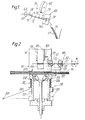
- Figure 2 is a schematic view illustrating the principles of one embodiment of stitcher suitable for use in the finisher of Figure 1,
- Figure 3 is scrap view of the stitcher shown in Figure I illustrating schematically the relationship of various parts of the stitcher,
- Figure 4 is a side elevation of the stitcher showing the drive for the clincher, and
- Figures 5 and 6 are like cross-sectional views of tne clincher showing the clincher ears in the positions assumed at the start and end of the clinching operation respectively.
- Referring to Figure 1 there is shown a
finisher 70 incorporating astitcher 100 according to this invention. The finisher is adapted to be arranged at the output of a photocopier represented in the drawing by the output nip rolls 64. 56 thereof. Although particularly well suited for use with a photocopier. the apparatus generally designated 100 is equally well adapted for use with any* number of devices in which cut sheets of material are delivered or compilec in a stack. - The finisher 7G comprises a
compiler tray 71 having a base orsupport surface 72 inclined downwardly in the direction of sheet travel towards a registration corner defined byregistration fences tray 71. Acorner registration device 79, such as a paddle wheel like that described in US Patent No 3669447, is arrangec over thesurface 72 to urge the sheets S into the registration corner to position them to receive a stitch from theapparatus 100. Theregistration fence 74 is rotatable about an axis 74a so that it may be retracted for ejection of bounc sets SS into acollection tray 79. Any suitable ejection mechanism, such as drive rollers, may be employed. - The
stitcher 100 may take any suitable form but a preferred form thereof is aescribed and illustratec in our copending European Application Nc 0013164. As shown in Figure 2, thestitcher 100 comprises astitcher head 101, a spool 102 (Figure 1) from which wire W is supplied to thehead 101 and anactive clincher 201 according to the invention. Thehead 101 includes a wire advancing and cutting mechanism generally indicated at 163 for presenting lengths of cut wire to the stitcher head, ananvil 104 for supporting the wire, a former 105 including two elements at opposite sides respectively of the driver for forming the wire into a generally U-shape about the anvil and adriver 106 for driving the formed staple through the set SS. Theclincher 201 comprises a clincher housing orsupport 202 having aclamping surface 203 by which a set SS may be clamped against the underside of thestitcher head 101 and containingclinch ears 210 arranged to receive and act upon staple legs driven through the set and into the housing through a slot in thesurface 203. - In Figure 2 the
clincher 201 is shown in its operative position with a set SS positioned against thehead 101 which is fixed in position above thecompiler tray 71. It will be understood, however, that during compilation of tne set, the clincher is lowered so that theclamping surface 203 is below the support the surface of the compiler tray 71 of the finisher. During a stitching operation the clincher 291 is raisec to lift the set SS against the underside of thehead 101 and clamp it in position. Variations ir set thicKness are accommodated by thedrive mechanism 210 by which the cincher housing is raised to lift the set against the underside of the stitcher head anc clamp it into position to receive a stitch. This mechanism comprises aforce applying ring 205 whicr lifts thehousing 202 wie acompression spring 206, being moved through a fixed distance by a lever 207 (see Figure 2). Thespring 206 is positioned between theforce applying ring 205 andshoulder 208 of thehousing 202. Thelever 207, which is arranged to pivot aboutaxis 209, is actuated by acam 219 and theclincher housing 202 is supported and guided by a pair ofarms 211 pivotally connectec between thehousing 202 and the frame of the stitcher. The lever 237 carries acam follower 270 intermediate theforce ring 205 andpivot axis 209 which is controlled by aface cam 219 the centre-line of the guideway of which is shown by the dash-dot line 219a. Thecam 270 is mounted on acam shaft 218. -
Tne mechanism 210 in addition to accommocating varying set thickness. varies the clamping pressure applied to the set as a function of set thickness. Thus, the thinner the set the less the compression ofspring 206 and the less the clamping force applied. Theclincher ears 204 are mounted on thehousing 202 so that they are always presented to the set in the same relation regardless of the set thickness. The drive to theclincher ears 204 is described below. - The wire advancing and cutting mechanism 103 comprises movable wire and
cutting blocks inhibitor member 124 positioned by theclincher 201 in dependence on the thickness of the set SS. Theblocks wire diodes blocks block 120 is moved to the left,diode 122 gripping the wire, to advance the wire passed the rest or start-of-cycle position of thecutter 125 by a distance made up of a constant crown length plus twice clinch length) plus the set thickness, anc thecutter block 121 is retracted from its rest position by a distance equal to the set thicKness. These movements and thus the length of wire W presented to thestitcner head 101 for severing by thecutter 125 is oeterminec by theinhibitor member 124 which limits the movement ofblocks blocks cutter block 121 returns to its rest position pulling the wire with it - so that the wire end is always in the same position at the start of a feed cycle - and the advancingblock 120 traverses bacK along the wire to its rest position. - The advancing
block 120 and thecutter block 121 are both mounted for horizontal sliding movement on a guide rail (not shown). In Figure 2, the wire advancing direction is from right to left and thecutter 125 is pivotally mounted on the left-hand end 127 of the cutter block which forms a shear face. The cutter is actuated by aprojection 109 on the former 105 as described below and is returned to its inactive position following an operating cycle by a tension spring not shown,. Theblocks wire dicres inhibitor member 124 is mounted for vertical sliding movement with theclincher housing 202 as schematically illustrated in Figure 2. Theinhibitor member 124 has two opposed 45° faces which are engaged by 45° faces 138, 139 respectively on the advancingblock 120 and thecutter block 121. Using 45° faces, the relationship between the position of the clincher housing and theinhibitor 124 is linear and 1:1. - While the
inhibitor member 124 may be directly connected to theclosher housing 202 as schematically represented in Figure 2, other arrangements are possible. Thus, as shown in Figure 7, theinhibitor member 124 is carried on anarm 143 pivoted to the stitcher head at 144 and :s positioned by means of anactuator 145 mounted on one of the clincher housing guidearms 211. As shown the actuator is adjustable for correctly setting the mechanism ano comprises abelt 146 threaded through abracket 147 and locked into position by anut 148. While the clincher is retreted. the innibitor is supported by alimit stop 149. - The length of wire presented tc the stitcher hear 101 by the mechanism 103 is cut, formed and driven in the following manner. while the april 104, which is pivotally mounted at 107 and biased to its start-of-cycle position by a
spring 108 as shown in Figure 3, is held against movement. thedriver 106 is moved downwardly against the wire to clamp it in position on the anvil. Theformer elements 105 then start moving downwardly. Initial movement of the former operates thecutter 125 throughactuator 109 to sever the required wire length and further movement thereof shapes the wire about theanvil 104 into a generaly U-shase In order to accommodate the wire during this operation the formers haveguide grooves 110 along their inner faces. At the end of a forming operating the former is in its lower limit position with the lower ends of theformer elements 105 below tne underside ofanvil 104 and adiacent the set. Thedriver 108 is now driven downwardly, pivoting the anvil about itsaxis 107. to drive the formed staple. As seen in Figure 3 the anvil includes asisping surface 104a. During the driving operation theanvil surface 104a forms a support for the crown of the staple. Similarly theformer elements 105 serve to support the legs of the staple in thegrooves 110 during the driving movement. - It will be realised from the foregoing that the anvil must be held against movement during the cutting and forming stage but be pushed out of the way during the driving stage. This may be achieved by using a spring 108 (Figure 3) which is strong enough to hold the anvil stationary during cutting and forming. However, this requires that the force available to drive the driver must be sufficient also to overcome the resistances of the spring. It is preferred therefore that the anvil be held locked in position during the cutting and forming stage and released by the former 105 at the end of its travel whereby only a relatively
light spring 108 is requirea which is sufficient to return the anvil to its start-of-cycle position and to ensure that the anvil supports the staple crown during the driving stage. One way of achieving this is shown in Figure 4 in which the anvil is geometrically locked in position during the cutting and forming steps by arranging thepivot axis 107 above the line of pressure engagement between driver and anvii. the locK being released by aprojection 190 on the former engaging anactuator surface 170 on the anvil support area. - As described above, the stitcher has a two stage driver action in which following wire feed a first stage motion operates to grip the wire W against the anvil 104 during cutting and forming and a second stage motion acts following forming to effect driving of the formed staple. A mechanism suitable for this operation based on pivoted motions which first holds the wire against the anvil and then provides the driving motion will form one continuous input lever travel described in our copending European Application No. 0013165.
- The ends of the staple legs are turned over and wiped flat against the underside of the set by the
clincher ears 204. Theclincher 201 and Its operation is described more fully below. However it should be noted that the clincher is operated so that the staple legs having passed through the set move through air and meet no further resistance during driver travel. This is achieved by arranging theclincher ears 204 out of the paths of the staple legs during driver travel. - The
clincher ears 204 are pivotall\ mounted on theclincher housing 202 by means ofaxles 220 which pass through slottedholes 212 in the ears. - Figure 5 shows the clincher ears in their inactive or start-of-cycle postions prior to the start of the clinching operation, in which position they are out of the paths of the staple legs. Figure 6 shows the positions of the ears at the end of a clinching operation. The ears are driven between these positions by an
actuator 223 is arranged for vertical sliding movement in the clincher housing, i.e. normally to thesurface 203, so as to rotate the clincher ears about theaxles 220 from the position shown in Figure 5 to that shown in Figure 6. During this rotational movement theupper surfaces 204a of the clincher ears wipe against the staple legs and bend them over against the bottom of the set. As shown in Figure 6, during the enc part of the movement of theears 204, the slottedholes 212 permit the ears to be translated in the direction of actuator movement normal to thesurface 203 so as to ensure that the ends of the staple legs are positively and firmly pressed flat against the underside of the set. - Grooves (not shown) are provided in the
upper surfaces 204a of the clincher ears to receive and guide the staple legs during bending thereof. These grooves should be wide enough tc accommodate normal leg wanaer. it being understood that normal leg wanaer is that whicf will occur except in the case of malformed or maverick staples or mis-feeas. - The
actuator 223 has ahead 224. which engages theundersides 204b of theclincher ears 204, mounted or anactuator roc 213 which extends out through the bottom of thehousing 202 anc is acted upon by acam crive 250 as shown in Figure 4. As illustrated in Figure 4 theclincher rod 213 is driven by an edge orramp cam 250 mounted on thesame drive shaft 218 as, and alongside, thecam 219 which drives the force-ring lever 207. The drive to the clincher rod from thecam 250 is effectea by aroller follower 251 mounted on one end of acrank arm 252 pivoted to abracket 253 depending outwardly from theclincher housing 202. The other end of the crank arm carries astop 254 which engages the bottom end of theclincher rod 213. As shown, thestop 254 is adjustable to permit setting of the clincher ear movement. Theclincher ears 204 are biassed to their open retracted position by a spring schematically represented in Figure 4 at 255. Thecam shaft 218 is driven in synchronism with thehead 101 drive and thecam 250 is disposed so that the clincher rod is driven only after the formed staple has been completely driven tnrough the set. It will be noted that by using a drive arrangement as snown with tne facecarr 250. variations in set thickness are accommodated without affecting the timing (except to an insignificant degree caused by slight variations in the position of thecam follower 251 tocam 250, of the clincher ear movement relative to that of the driver. - Although schematically illustrated in Figure 2 as being a solid member, it will be seen from Figures 5 and 6 that the
actuator rod 213 is in two relativelymovable parts 213a and 213b. It will also be seen that despite the simplified representation of aspring 255 in Figure 4, there are twocompression springs spring 255a biases the twoparts 213a and 213b of the actuator rod apart, being mounted betweenflanges 256. 257 on theactuator rod parts 213a and 213b respectively. Thespring 255b biasses theactuator rod 213 to its retracted position, being mounted betweer a fixedflange 258 in thehousing 202 and theflange 256. Thespring 255a is stronger than thespring 255b so that during clinching movement of therod 213 thespring 255b is compressed with the actuator rod parts 213a. 213b solidly joined by thespring 255a. At the end of the clinching cyxcle further movement of therod part 213b by thecam drive 250 will be accommodated by. thespring 255a, which defines the clinching force. -
Tne undersides 204b of theclincher ears 204 are partly curved in order to provide a smooth rotational movement of the ears and include flat portions engaged by theactuator head 224 at the end of the rotational movement of the ears and during their translational movement. The slottedholes 212 in the ears are arranged and dimensioned so that the ears translate at the enc of rotational movements thereof but it will be understood that by having theaxles 220 loosely fitted within theholes 212 translation of theears 204 will occur during the end part of their rotational movements. -
Nose portions 222 provioed in theclincher ears 204 are engaged by thehead 224 of theactuator 223 as it is retracted at the end of a clinching operation to return the clincher ears to their inactive positions. Retraction of the actuator is, of course, effected by thesprings actuator rod 213. - It is to be understood that although Figures 5 and 6 illustrate the principle of operation of a clincher according to the invention. in practice the clincher ears would be closer together or longer so that in the position shown in Figure 6 the adjacent ends of the ears are closely spaced. This is necessary in order to act positively and firmly on the staple legs and support the turned-over portions (clinches) of the staple legs througnout their lengths.
- Whilst a specific embodiment of the invention has been described above it will be understood that various modifications may be made to the specific details referred to herein without departing from the scope of the invention as defined in the appended claims. For example it will be understood that while in the embodiment described the stitcher head is fixed, the clincher could be fixed and the clamping means be formed by the sheet receiving surface of the head itself.
Claims (6)
Applications Claiming Priority (2)
| Application Number | Priority Date | Filing Date | Title |
|---|---|---|---|
| GB8219713 | 1982-07-07 | ||
| GB8219713 | 1982-07-07 |
Publications (2)
| Publication Number | Publication Date |
|---|---|
| EP0099249A1 true EP0099249A1 (en) | 1984-01-25 |
| EP0099249B1 EP0099249B1 (en) | 1986-04-30 |
Family
ID=10531538
Family Applications (1)
| Application Number | Title | Priority Date | Filing Date |
|---|---|---|---|
| EP83303970A Expired EP0099249B1 (en) | 1982-07-07 | 1983-07-07 | Active clinchers and wire stitchers incorporating same |
Country Status (5)
| Country | Link |
|---|---|
| US (1) | US4546910A (en) |
| EP (1) | EP0099249B1 (en) |
| JP (1) | JPS5952697A (en) |
| CA (1) | CA1208401A (en) |
| DE (1) | DE3363272D1 (en) |
Families Citing this family (19)
| Publication number | Priority date | Publication date | Assignee | Title |
|---|---|---|---|---|
| JPH0628844B2 (en) * | 1986-05-28 | 1994-04-20 | キヤノン株式会社 | Stapling device in the finisher device |
| DE3855369T2 (en) * | 1987-12-28 | 1996-11-07 | Max Co Ltd | Electric stapler |
| DE3903133A1 (en) * | 1988-02-04 | 1989-08-31 | Amada Co | WORKPIECE WORKABILITY DETECTION METHOD AND METHOD FOR MACHINING A WORKPIECE BY MEANS OF A CHIP MACHINING MACHINE USING THIS METHOD |
| JPH0215378U (en) * | 1988-07-14 | 1990-01-31 | ||
| US4898314A (en) * | 1988-10-20 | 1990-02-06 | International Business Machines Corporation | Method and apparatus for stitcher wire loading |
| US5004142A (en) * | 1989-01-23 | 1991-04-02 | Swingline Inc. | Guide anvil including movable clinching wings for stapler |
| US5106066A (en) * | 1990-11-01 | 1992-04-21 | Eastman Kodak Company | Stapling system feed mechanism |
| US5133493A (en) * | 1990-11-01 | 1992-07-28 | Eastman Kodak Company | Stapling system having noise reducing work clamp |
| US5586710A (en) * | 1992-11-13 | 1996-12-24 | Roll Systems, Inc. | Power stapler |
| DE4303503A1 (en) * | 1993-02-06 | 1994-08-11 | Kodak Ag | Stapler for stapling sheets together |
| JP2923938B2 (en) * | 1995-02-03 | 1999-07-26 | マックス株式会社 | Spelling abnormality detection mechanism in stapler |
| DE19607296A1 (en) * | 1996-02-27 | 1997-08-28 | Kodak Ag | Stitching device for fastening stack-shaped sheets |
| US6044872A (en) * | 1998-10-09 | 2000-04-04 | Stephens; Donald R. | Fence clip installer |
| US6237828B1 (en) | 1998-10-27 | 2001-05-29 | Roll Systems, Inc. | Stapler and guide assembly for same |
| US6547230B2 (en) * | 2001-03-20 | 2003-04-15 | Toshiba Tec Kabushiki Kaisha | Stapler with variable staple english |
| GB2376912B (en) * | 2001-06-27 | 2003-04-09 | Isaberg Rapid Ab | Clinching mechanism for staplers |
| JP4232371B2 (en) * | 2002-01-11 | 2009-03-04 | マックス株式会社 | stapler |
| WO2005030442A2 (en) * | 2003-09-26 | 2005-04-07 | Duff William G | Staple forming apparatus |
| US10773414B2 (en) * | 2016-11-12 | 2020-09-15 | Udaykumar Chhabildas PATEL | Servo controlled stitching apparatus and method thereof |
Citations (9)
| Publication number | Priority date | Publication date | Assignee | Title |
|---|---|---|---|---|
| DE82392C (en) * | ||||
| US603438A (en) * | 1898-05-03 | The nonnis peters co | ||
| US670624A (en) * | 1900-12-07 | 1901-03-26 | Cottrell C B & Sons Co | Paper folding and stapling machine. |
| US1675779A (en) * | 1926-07-17 | 1928-07-03 | Morrison Stitcher Corp | Clincher for wire-stapling machines |
| AT127538B (en) * | 1929-11-20 | 1932-03-25 | Otto Luetolf | Method and stapling head for stapling folded sheets to ribbons. |
| EP0013165A1 (en) * | 1978-12-29 | 1980-07-09 | Xerox Corporation | Improvements in wire stitchers |
| EP0013163A1 (en) * | 1978-12-29 | 1980-07-09 | Xerox Corporation | Active clinchers and wire stitchers incorporating same |
| EP0013159A1 (en) * | 1978-12-29 | 1980-07-09 | Xerox Corporation | Improvements in wire stitchers |
| EP0013164B1 (en) * | 1978-12-29 | 1984-09-12 | Xerox Corporation | Wire stitchers and methods of binding sets of sheets |
Family Cites Families (9)
| Publication number | Priority date | Publication date | Assignee | Title |
|---|---|---|---|---|
| US2964749A (en) * | 1955-06-15 | 1960-12-20 | Gen Mills Inc | Attaching electrical components |
| US2902689A (en) * | 1957-07-01 | 1959-09-08 | Gen Mills Inc | Component attaching machine |
| US2987729A (en) * | 1959-02-10 | 1961-06-13 | Melpar Inc | Stapling device |
| US3669447A (en) * | 1970-09-09 | 1972-06-13 | Xerox Corp | Sheet propelling apparatus |
| US3804317A (en) * | 1971-11-24 | 1974-04-16 | J Gelzer | Wiping anvil assembly for bending component leads |
| CH549443A (en) * | 1973-03-26 | 1974-05-31 | Grapha Holding Ag | METHOD AND STAPLER FOR THE PRODUCTION OF EYE STAPLES IN THE STAPLER OF A WIRE STAPLING MACHINE AND FOR STAPLING FOLDED SHEETS WITH THE EYELET STAPLES. |
| US3986533A (en) * | 1975-11-26 | 1976-10-19 | Usm Corporation | Mechanism for clinching leads inwardly or outwardly |
| US4194666A (en) * | 1978-06-26 | 1980-03-25 | Xerox Corporation | Staple clinching mechanism |
| US4389011A (en) * | 1978-12-29 | 1983-06-21 | Xerox Corporation | Stitching machine |
-
1983
- 1983-07-05 US US06/511,033 patent/US4546910A/en not_active Expired - Lifetime
- 1983-07-06 CA CA000431951A patent/CA1208401A/en not_active Expired
- 1983-07-07 DE DE8383303970T patent/DE3363272D1/en not_active Expired
- 1983-07-07 JP JP58124041A patent/JPS5952697A/en active Granted
- 1983-07-07 EP EP83303970A patent/EP0099249B1/en not_active Expired
Patent Citations (9)
| Publication number | Priority date | Publication date | Assignee | Title |
|---|---|---|---|---|
| DE82392C (en) * | ||||
| US603438A (en) * | 1898-05-03 | The nonnis peters co | ||
| US670624A (en) * | 1900-12-07 | 1901-03-26 | Cottrell C B & Sons Co | Paper folding and stapling machine. |
| US1675779A (en) * | 1926-07-17 | 1928-07-03 | Morrison Stitcher Corp | Clincher for wire-stapling machines |
| AT127538B (en) * | 1929-11-20 | 1932-03-25 | Otto Luetolf | Method and stapling head for stapling folded sheets to ribbons. |
| EP0013165A1 (en) * | 1978-12-29 | 1980-07-09 | Xerox Corporation | Improvements in wire stitchers |
| EP0013163A1 (en) * | 1978-12-29 | 1980-07-09 | Xerox Corporation | Active clinchers and wire stitchers incorporating same |
| EP0013159A1 (en) * | 1978-12-29 | 1980-07-09 | Xerox Corporation | Improvements in wire stitchers |
| EP0013164B1 (en) * | 1978-12-29 | 1984-09-12 | Xerox Corporation | Wire stitchers and methods of binding sets of sheets |
Also Published As
| Publication number | Publication date |
|---|---|
| CA1208401A (en) | 1986-07-29 |
| US4546910A (en) | 1985-10-15 |
| JPH0585358B2 (en) | 1993-12-07 |
| JPS5952697A (en) | 1984-03-27 |
| EP0099249B1 (en) | 1986-04-30 |
| DE3363272D1 (en) | 1986-06-05 |
Similar Documents
| Publication | Publication Date | Title |
|---|---|---|
| EP0099249B1 (en) | Active clinchers and wire stitchers incorporating same | |
| US5806750A (en) | Automatic stapling device | |
| US4378085A (en) | Stapler apparatus having a mechanism for bending and cutting staple legs in accordance with the thickness of the work piece | |
| US6036074A (en) | Staple clinching mechanism in stapler | |
| US5460314A (en) | Stapler with improved stapling precision | |
| CA1143101A (en) | Stitchers | |
| EP0389599B1 (en) | Device for stapling a stack of sheets | |
| EP0013163B1 (en) | Active clinchers and wire stitchers incorporating same | |
| CA1143102A (en) | Stitchers | |
| US4358040A (en) | Stitchers | |
| EP2111957B1 (en) | Staple feeding mechanism in stapler | |
| EP0013164B1 (en) | Wire stitchers and methods of binding sets of sheets | |
| US4389011A (en) | Stitching machine | |
| EP1220737B1 (en) | Stapler for forming staples to various sizes | |
| JPH11207652A (en) | Staple device | |
| US4369908A (en) | Stitchers | |
| US4358042A (en) | Wire stitchers | |
| US4416046A (en) | Method of binding sheets using stitchers | |
| US6641023B2 (en) | Anti-reversing device in a staple magazine | |
| JP3975354B2 (en) | Return mechanism in stapler | |
| JP4304971B2 (en) | Paper thickness adjustment mechanism in an electric stapler | |
| JPH061336Y2 (en) | Buckling prevention device for stapler | |
| GB2112452A (en) | Securing bottom end stop to fastener chain | |
| KR20070050462A (en) | Stapler | |
| JP2000190250A (en) | Automatic stapler device |
Legal Events
| Date | Code | Title | Description |
|---|---|---|---|
| PUAI | Public reference made under article 153(3) epc to a published international application that has entered the european phase |
Free format text: ORIGINAL CODE: 0009012 |
|
| AK | Designated contracting states |
Designated state(s): DE FR GB |
|
| 17P | Request for examination filed |
Effective date: 19840710 |
|
| GRAA | (expected) grant |
Free format text: ORIGINAL CODE: 0009210 |
|
| AK | Designated contracting states |
Kind code of ref document: B1 Designated state(s): DE FR GB |
|
| REF | Corresponds to: |
Ref document number: 3363272 Country of ref document: DE Date of ref document: 19860605 |
|
| ET | Fr: translation filed | ||
| PLBE | No opposition filed within time limit |
Free format text: ORIGINAL CODE: 0009261 |
|
| STAA | Information on the status of an ep patent application or granted ep patent |
Free format text: STATUS: NO OPPOSITION FILED WITHIN TIME LIMIT |
|
| 26N | No opposition filed | ||
| PGFP | Annual fee paid to national office [announced via postgrant information from national office to epo] |
Ref country code: GB Payment date: 19990707 Year of fee payment: 17 |
|
| PGFP | Annual fee paid to national office [announced via postgrant information from national office to epo] |
Ref country code: FR Payment date: 19990709 Year of fee payment: 17 |
|
| PGFP | Annual fee paid to national office [announced via postgrant information from national office to epo] |
Ref country code: DE Payment date: 19990712 Year of fee payment: 17 |
|
| PG25 | Lapsed in a contracting state [announced via postgrant information from national office to epo] |
Ref country code: GB Free format text: LAPSE BECAUSE OF NON-PAYMENT OF DUE FEES Effective date: 20000707 |
|
| GBPC | Gb: european patent ceased through non-payment of renewal fee |
Effective date: 20000707 |
|
| PG25 | Lapsed in a contracting state [announced via postgrant information from national office to epo] |
Ref country code: FR Free format text: LAPSE BECAUSE OF NON-PAYMENT OF DUE FEES Effective date: 20010330 |
|
| REG | Reference to a national code |
Ref country code: FR Ref legal event code: ST |
|
| PG25 | Lapsed in a contracting state [announced via postgrant information from national office to epo] |
Ref country code: DE Free format text: LAPSE BECAUSE OF NON-PAYMENT OF DUE FEES Effective date: 20010501 |