EP0099134B1 - Fluid control valve apparatus - Google Patents
Fluid control valve apparatus Download PDFInfo
- Publication number
- EP0099134B1 EP0099134B1 EP19830106966 EP83106966A EP0099134B1 EP 0099134 B1 EP0099134 B1 EP 0099134B1 EP 19830106966 EP19830106966 EP 19830106966 EP 83106966 A EP83106966 A EP 83106966A EP 0099134 B1 EP0099134 B1 EP 0099134B1
- Authority
- EP
- European Patent Office
- Prior art keywords
- valve
- chamber
- pilot
- logic
- valve body
- Prior art date
- Legal status (The legal status is an assumption and is not a legal conclusion. Google has not performed a legal analysis and makes no representation as to the accuracy of the status listed.)
- Expired
Links
Images


Classifications
-
- F—MECHANICAL ENGINEERING; LIGHTING; HEATING; WEAPONS; BLASTING
- F16—ENGINEERING ELEMENTS AND UNITS; GENERAL MEASURES FOR PRODUCING AND MAINTAINING EFFECTIVE FUNCTIONING OF MACHINES OR INSTALLATIONS; THERMAL INSULATION IN GENERAL
- F16K—VALVES; TAPS; COCKS; ACTUATING-FLOATS; DEVICES FOR VENTING OR AERATING
- F16K31/00—Actuating devices; Operating means; Releasing devices
- F16K31/12—Actuating devices; Operating means; Releasing devices actuated by fluid
- F16K31/14—Actuating devices; Operating means; Releasing devices actuated by fluid for mounting on, or in combination with, hand-actuated valves
- F16K31/143—Actuating devices; Operating means; Releasing devices actuated by fluid for mounting on, or in combination with, hand-actuated valves the fluid acting on a piston
-
- F—MECHANICAL ENGINEERING; LIGHTING; HEATING; WEAPONS; BLASTING
- F16—ENGINEERING ELEMENTS AND UNITS; GENERAL MEASURES FOR PRODUCING AND MAINTAINING EFFECTIVE FUNCTIONING OF MACHINES OR INSTALLATIONS; THERMAL INSULATION IN GENERAL
- F16K—VALVES; TAPS; COCKS; ACTUATING-FLOATS; DEVICES FOR VENTING OR AERATING
- F16K17/00—Safety valves; Equalising valves, e.g. pressure relief valves
- F16K17/02—Safety valves; Equalising valves, e.g. pressure relief valves opening on surplus pressure on one side; closing on insufficient pressure on one side
- F16K17/04—Safety valves; Equalising valves, e.g. pressure relief valves opening on surplus pressure on one side; closing on insufficient pressure on one side spring-loaded
- F16K17/10—Safety valves; Equalising valves, e.g. pressure relief valves opening on surplus pressure on one side; closing on insufficient pressure on one side spring-loaded with auxiliary valve for fluid operation of the main valve
-
- F—MECHANICAL ENGINEERING; LIGHTING; HEATING; WEAPONS; BLASTING
- F15—FLUID-PRESSURE ACTUATORS; HYDRAULICS OR PNEUMATICS IN GENERAL
- F15B—SYSTEMS ACTING BY MEANS OF FLUIDS IN GENERAL; FLUID-PRESSURE ACTUATORS, e.g. SERVOMOTORS; DETAILS OF FLUID-PRESSURE SYSTEMS, NOT OTHERWISE PROVIDED FOR
- F15B13/00—Details of servomotor systems ; Valves for servomotor systems
- F15B13/02—Fluid distribution or supply devices characterised by their adaptation to the control of servomotors
- F15B13/04—Fluid distribution or supply devices characterised by their adaptation to the control of servomotors for use with a single servomotor
- F15B13/0401—Valve members; Fluid interconnections therefor
- F15B13/0405—Valve members; Fluid interconnections therefor for seat valves, i.e. poppet valves
-
- F—MECHANICAL ENGINEERING; LIGHTING; HEATING; WEAPONS; BLASTING
- F15—FLUID-PRESSURE ACTUATORS; HYDRAULICS OR PNEUMATICS IN GENERAL
- F15B—SYSTEMS ACTING BY MEANS OF FLUIDS IN GENERAL; FLUID-PRESSURE ACTUATORS, e.g. SERVOMOTORS; DETAILS OF FLUID-PRESSURE SYSTEMS, NOT OTHERWISE PROVIDED FOR
- F15B13/00—Details of servomotor systems ; Valves for servomotor systems
- F15B13/02—Fluid distribution or supply devices characterised by their adaptation to the control of servomotors
- F15B13/04—Fluid distribution or supply devices characterised by their adaptation to the control of servomotors for use with a single servomotor
- F15B13/042—Fluid distribution or supply devices characterised by their adaptation to the control of servomotors for use with a single servomotor operated by fluid pressure
- F15B13/043—Fluid distribution or supply devices characterised by their adaptation to the control of servomotors for use with a single servomotor operated by fluid pressure with electrically-controlled pilot valves
- F15B13/0431—Fluid distribution or supply devices characterised by their adaptation to the control of servomotors for use with a single servomotor operated by fluid pressure with electrically-controlled pilot valves the electrical control resulting in an on-off function
-
- F—MECHANICAL ENGINEERING; LIGHTING; HEATING; WEAPONS; BLASTING
- F16—ENGINEERING ELEMENTS AND UNITS; GENERAL MEASURES FOR PRODUCING AND MAINTAINING EFFECTIVE FUNCTIONING OF MACHINES OR INSTALLATIONS; THERMAL INSULATION IN GENERAL
- F16K—VALVES; TAPS; COCKS; ACTUATING-FLOATS; DEVICES FOR VENTING OR AERATING
- F16K31/00—Actuating devices; Operating means; Releasing devices
- F16K31/12—Actuating devices; Operating means; Releasing devices actuated by fluid
- F16K31/122—Actuating devices; Operating means; Releasing devices actuated by fluid the fluid acting on a piston
-
- F—MECHANICAL ENGINEERING; LIGHTING; HEATING; WEAPONS; BLASTING
- F15—FLUID-PRESSURE ACTUATORS; HYDRAULICS OR PNEUMATICS IN GENERAL
- F15B—SYSTEMS ACTING BY MEANS OF FLUIDS IN GENERAL; FLUID-PRESSURE ACTUATORS, e.g. SERVOMOTORS; DETAILS OF FLUID-PRESSURE SYSTEMS, NOT OTHERWISE PROVIDED FOR
- F15B2211/00—Circuits for servomotor systems
- F15B2211/30—Directional control
- F15B2211/305—Directional control characterised by the type of valves
- F15B2211/3056—Assemblies of multiple valves
- F15B2211/30565—Assemblies of multiple valves having multiple valves for a single output member, e.g. for creating higher valve function by use of multiple valves like two 2/2-valves replacing a 5/3-valve
- F15B2211/30575—Assemblies of multiple valves having multiple valves for a single output member, e.g. for creating higher valve function by use of multiple valves like two 2/2-valves replacing a 5/3-valve in a Wheatstone Bridge arrangement (also half bridges)
-
- F—MECHANICAL ENGINEERING; LIGHTING; HEATING; WEAPONS; BLASTING
- F15—FLUID-PRESSURE ACTUATORS; HYDRAULICS OR PNEUMATICS IN GENERAL
- F15B—SYSTEMS ACTING BY MEANS OF FLUIDS IN GENERAL; FLUID-PRESSURE ACTUATORS, e.g. SERVOMOTORS; DETAILS OF FLUID-PRESSURE SYSTEMS, NOT OTHERWISE PROVIDED FOR
- F15B2211/00—Circuits for servomotor systems
- F15B2211/30—Directional control
- F15B2211/32—Directional control characterised by the type of actuation
- F15B2211/329—Directional control characterised by the type of actuation actuated by fluid pressure
-
- Y—GENERAL TAGGING OF NEW TECHNOLOGICAL DEVELOPMENTS; GENERAL TAGGING OF CROSS-SECTIONAL TECHNOLOGIES SPANNING OVER SEVERAL SECTIONS OF THE IPC; TECHNICAL SUBJECTS COVERED BY FORMER USPC CROSS-REFERENCE ART COLLECTIONS [XRACs] AND DIGESTS
- Y10—TECHNICAL SUBJECTS COVERED BY FORMER USPC
- Y10S—TECHNICAL SUBJECTS COVERED BY FORMER USPC CROSS-REFERENCE ART COLLECTIONS [XRACs] AND DIGESTS
- Y10S251/00—Valves and valve actuation
- Y10S251/90—Valves with o-rings
-
- Y—GENERAL TAGGING OF NEW TECHNOLOGICAL DEVELOPMENTS; GENERAL TAGGING OF CROSS-SECTIONAL TECHNOLOGIES SPANNING OVER SEVERAL SECTIONS OF THE IPC; TECHNICAL SUBJECTS COVERED BY FORMER USPC CROSS-REFERENCE ART COLLECTIONS [XRACs] AND DIGESTS
- Y10—TECHNICAL SUBJECTS COVERED BY FORMER USPC
- Y10T—TECHNICAL SUBJECTS COVERED BY FORMER US CLASSIFICATION
- Y10T137/00—Fluid handling
- Y10T137/8593—Systems
- Y10T137/87169—Supply and exhaust
- Y10T137/87193—Pilot-actuated
- Y10T137/87209—Electric
Landscapes
- Engineering & Computer Science (AREA)
- General Engineering & Computer Science (AREA)
- Mechanical Engineering (AREA)
- Physics & Mathematics (AREA)
- Fluid Mechanics (AREA)
- Fluid-Driven Valves (AREA)
- Safety Valves (AREA)
- Fluid-Pressure Circuits (AREA)
Description
- This invention relates to fluid control valve apparatus equipped with logic valve means operative in response to pilot pressure signals, and more particularly it is concerned with a fluid control valve apparatus of the type described which has particular utility in controlling a supply of hydraulic fluid to a hydraulic actuator in a hydraulic fluid circuit for a hydraulic construction machine, such as a hydraulic excavator.
- In hydraulic construction machines, such as hydraulic excavators, of the prior art, it has hitherto been usual practice to use fluid control valve apparatus of the type including spool type directional control valves for controlling a supply of hydraulic fluid to the hydraulic actuator. This type of directional control valves have suffered the disadvantage that, since a sliding gap is necessary between the spool valve body and the valve casing, internal leaks of the fluid through this gap might be unavoidable and, when the actuator is a cylinder, inadvertent displacement of the cylinder by gravity might occur.
- In view of the aforesaid disadvantage of the spool type directional control valves, proposals have in recent years been made to use poppet type logic valves to constitute fluid control valve apparatus with an eye to the advantage offered by them that internal leaks of the fluid can be eliminated.
- Generally, the poppet type logic valves proposed for use to constitute fluid control valve apparatus each comprise a poppet type valve body located for movement in a valve chamber defined in a valve housing, and a conical surface portion is formed on a forward end of the valve body. The conical surface portion is brought into fluidtight contact with a valve seat formed in the valve housing when the valve body moves in a valve closing direction, to bring first and second hydraulic fluid chambers out of communication with each other. This brings a first main port formed in the first hydraulic fluid chamber out of communication with a second main port formed in the second hydraulic fluid chamber. A pilot chamber is defined between an end of the valve body opposite to the conical surface portion and the inner surface of an end cover of the valve housing, and a pilot pressure signal is applied through a pilot port formed in the end cover to the pilot chamber which has a spring mounted therein, so that the valve body is urged by the pilot pressure signal and the biasing force of the spring to move to a position in which the valve body closes the logic valve.
- When the pilot pressure signal is at a reservoir pressure level (zero or substantially zero), a flow of pressurized fluid from the first main port to the second main port acts on the pressure receiving area of the valve body which corresponds to the diameter of the valve body and forces same to move upwardly to bring the first and second main ports into communication with each other. A flow of pressurized fluid from the second main port to the first main port acts on the annular pressure receiving area of the valve body which corresponds to the difference between the diameter of the valve body and the diameter of the valve seat and forces same to move upwardly to bring the first and second main ports into communication with each other.
- When the pilot pressure valve reaches a predetermined high pressure level or the pilot port is blocked, forcing of the valve body to move upwardly by the pressure at the first and second main ports is interrupted, thereby bringing the first and second main ports out of communication with each other.
- When the fluid control valve apparatus equipped with logic valves of the aforesaid construction is used in a hydraulic fluid circuit including a hydraulic actuator for controlling a supply of hydraulic fluid to the hydraulic actuator, the first and second main ports are connected to main circuit lines thereof, and the pilot port is connected through a pilot valve to shuttle valves connected to the main circuit lines and a reservoir, so that the pilot port is able to selectively introduce into the pilot chamber as a pilot pressure signal either a highest pressure in the hydraulic fluid circuit or a reservoir pressure. When the hydraulic actuator is connected to a hydraulic pump in an open circuit, the logic valves used are four in number. A fluid control valve apparatus comprising four logic valves is disclosed, for example, in JP-A-57-43063.
- In the fluid control valve apparatus of the aforesaid construction, when the logic valve is to be opened, the pilot valve is actuated to introduce a reservoir pressure into the pilot port as a pilot pressure signal. This causes the main circuit line pressure in the first main port or second main port to force the valve body to move upwardly to bring the valve to an open position. When the logic valve is to be closed, the pilot valve is actuated to introduce into the pilot port as a pilot pressure signal a highest pressure in the hydraulic pressure circuit. As a result, a force tending to urge the valve body to move downwardly by the pressure in the pilot chamber overcomes a force tending to move the valve body upwardly by the main circuit line pressure in the first main port or second main port, to thereby bring the valve to a closed position.
- As described hereinabove, in fluid control valve apparatus of the prior art, the logic valve is opened or closed depending on the relative magnitudes of the force tending to force the valve body to move upwardly by a pilot pressure signal and the force tending to force the valve body to move downwardly by a pressure in the first main port or second main port. Thus, the logic valve is of construction that the operation is essentially susceptible to the influences exerted by a variation in the pressure in the first main port or second main port. Also in the fluid control valve apparatus in the aforesaid specific connection, the first main port or second main port of the logic valves has a main circuit line pressure of the hydraulic fluid circuit applied thereto which has a value tending to undergo a variation of high magnitude depending on the operating condition of the hydraulic actuator. Thus, the operation of the logic valves would be influenced by a variation in main circuit line pressure. For example, assume that the main circuit line pressure introduced into the first and second main ports reaches a highest level of the pressure prevailing in the hydraulic fluid circuit and the highest pressure is introduced as a pilot pressure signal into the pilot port which has been brought out of communication with the reservoir when the valve is to be closed. Then the speed at which the valve is closed would become extremely low, showing poor responsiveness, since the valve body is operated only by being downwardly moved by the spring installed in the pilot chamber. Also, when the reservoir pressure is introduced into the pilot port as a pilot pressure signal to open the valve where the main circuit line pressure introduced into the main port is extremely high or when the highest circuit pressure is introduced into the pilot port as a pilot pressure signal to close the valve where the main circuit line pressure introduced into the main port is extremely low, the difference in pressure between the pressure in the main port and the pressure introduced into the pilot port as a pilot pressure signal becomes great, so that the speed at which the valve is opened or closed would become extremely high and the flow rate of the hydraulic fluid would show a sudden change, thereby giving a great shock to the hydraulic fluid circuit and the actuator. Particularly, when the speed at which the valve is closed becomes extremely high, the valve body would be thrown against the valve body, so that the conical surface portion of the valve body might be damaged by the valve seat. Also, abrupt blocking of communication between the first main port and second main port might apply a surge pressure to the first or second main port due to the water hammer phenomenon, thereby exerting injurious influences on the hydraulic fluid circuit or actuator.
- The fluid control valve apparatus of this construction has suffered an additional disadvantage in that since a high pressure is introduced from the hydraulic fluid circuit to the pilot port of the logic valves, the high pressure would also be applied to a pilot line and the latter would tend to suffer damage.
- A main object of the invention is to provide a fluid control valve apparatus including logic valve means wherein a pressure in the main port exerts substantially no influences on the movement of the valve body in valve opening and valve closing operation, so that no uncontrolled acceleration and deceleration are caused to occur in the operation of the valve body by a variation in the pressure in the main port.
- Another object of the invention is to provide a fluid control valve apparatus including logic valve means wherein the valve has good responsiveness to a signal for opening or closing the valve, and damage to the valve body and production of a surge pressure and a shock which might be caused during its movement in valve closing and opening directions can be minimized.
- Still another object of the invention is to provide a fluid control valve apparatus including logic valve means wherein damage to the pilot line difficultly occurs.
- According to the invention, there is provided a fluid control valve apparatus comprising logic valve means comprising a valve housing, a first valve chamber defined in the valve housing, a valve body arranged in the first valve chamber for fluidtight movement in an axial direction, the valve body including opposite end portions and a conical surface portion, a valve seat adapted to be brought into fluidtight sealing contact with the conical surface portion of the valve body when the valve body moves in a valve closing direction, a first hydraulic fluid chamber and a second hydraulic fluid chamber defined in the valve housing and adapted to be brought into communication with each other when the conical surface portion of the valve body is released from contact with the valve seat and brought out of communication with each other when the conical surface portion of the valve body is brought into contact with the valve seat, and a first pilot chamber defined in the valve housing adjacent one end portion of the valve body and operative to force the valve body to move in the valve closing direction by a first pilot pressure signal received therein, characterised in that the logic valve means further comprises a second valve chamber defined in the valve housing, a valve body extension formed by extending the other end portion of the valve body through the first hydraulic fluid chamber and arranged in the second valve chamber for fluidtight movement in an axial direction, and a second pilot chamber defined in the valve housing adjacent an end of the valve body extension and operative to force the valve body extension to move in a valve opening direction by a second pilot pressure signal received therein, the second pilot chamber being independent of the first pilot chamber with respect to hydraulic pressures.
- Preferably, the logic valve means comprises damper means located adjacent the end of the valve body extension for abutting engagement with the end immediately before the valve body is brought into contact with the valve seat.
- Preferably, the fluid control valve apparatus further comprises a sleeve comprising a sleeve body defining the first valve chamber and a positioning flange located adjacent the first pilot chamber, the sleeve body being loosely fitted in the valve housing and the flange being fluidtightly arranged in the valve chamber through seal rings interposed between side surfaces of the flange and the valve housing.
- Preferably, the valve seat of the logic valve means is in the form of a conical convex surface having a greater vertical angle than the conical surface portion of the valve body, and the difference in vertical angle between them is in a predetermined range.
- Preferably, the fluid control valve apparatus further comprises logic valve control means comprising reference pressure setting means for applying a substantially constant reference pressure at all times to the first pilot chamber of the logic valve means as a first pilot pressure signal, and switch means for applying to the second pilot chamber of the logic valve means as a second pilot pressure signal a first predetermined pressure higher than the reference pressure when the valve is to be opened and applying to the second pilot chamber of the logic valve means as a second pilot pressure signal a second predetermined pressure lower than the reference pressure when the valve is to be closed.
- Preferably, the switch means comprises a first on-off valve and a second on-off valve comprising high-speed, solenoid-operated on-off valves, and the logic valve control means further comprises pulse producing means providing pulse outputs to electromagnetic means of each of the solenoid-operated on-off valves.
- Preferably, the fluid control valve apparatus further comprises logic valve control means comprising first switch means for applying a first predetermined pressure of a relatively high level as a first pilot pressure signal to the first pilot chamber of the logic valve means when the logic valve means is to be closed, and applying a second predetermined pressure of a relatively low level to the first pilot chamber with a slight time lag when the logic valve means is to be opened, and second switch means for applying a third predetermined pressure of a relatively low level to the second pilot chamber of the logic valve means as a second pilot pressure signal when the logic valve means is to be closed and applying a fourth predetermined pressure of a relatively high level to the second pilot chamber when the logic valve means is to be opened.
-
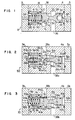
- Fig. 1 is a sectional view of a logic valve of the fluid control valve apparatus comprising a preferred embodiment of the invention;
- Fig. 2 is a sectional view of a logic valve of the fluid control valve apparatus comprising another preferred embodiment;
- Fig. 3 is a sectional view of a logic valve of the fluid control valve apparatus comprising still another preferred embodiment;
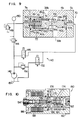
- Fig. 4 is a sectional view of a modification of the logic valve shown in Fig. 1 which is provided with damper means;
- Fig. 5 is a sectional view of a modification of the logic valve shown in Fig. 1, in which the sleeve and seal means of the logic valve are modified;
- Fig. 6 is a view, on an enlarged scale, of the flange of the sleeve of the logic valve shown in Fig. 5 and its surroundings;
- Fig. 7 is a sectional view of a modification of the logic valve shown in Fig. 1 in which the valve seat is modified;
- Fig. 8 is a view, on an enlarged scale, of the conical surface portion of the valve body and the valve seat portion shown in Fig. 7;
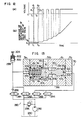
- Fig. 9 is a circuit diagram showing one example of the logic valve control means of the fluid control valve apparatus according to the invention, showing the logic valve control means in combination with the logic valve shown in Fig. 3;
- Fig. 10 is a sectional view of a high-speed, solenoid-operated on-off valve suitable for use as switch means of the logic valve control means of the fluid control valve apparatus according to the invention;
- Fig. 11 is a circuit diagram showing one example of the control means for four logic valves connected to a hydraulic fluid circuit comprising the logic valve control means shown in Fig. 9 as a basic component and using the high-speed, solenoid-operated on-off valves shown in Fig. 10 as switch means;
- Fig. 12 is a graph showing the magnitude of displacement of the valve body in relation to the duration of a pulse supplied to one logic valve in the control means shown in Fig. 11;
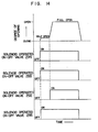
- Fig. 13 is a circuit diagram showing another example of the logic valve control means of the fluid control valve apparatus according to the invention, showing the logic valve control means in combination with the logic valve shown in Fig. 3; and
- Fig. 14 is a time chart showing the timing of signals supplied to the solenoid-operated on-off valves of the control means shown in Fig. 13.
- Referring to Fig. 1, a logic valve of a preferred embodiment of the fluid control valve apparatus in conformity with the invention is generally designated by the
reference numeral 2. Thelogic valve 2 comprises avalve housing 4 includingend covers valve housing 4 to define a first valve chamber 8 by its inner peripheral surface. A portion of avalve body 10 is arranged in the first valve chamber 8 for liquid- tight movement in an axial direction. Thevalve body 10 is formed with a conical surface portion 12 which is brought into fluidtight contact with a 'valve seat 14 formed in thevalve housing 4. A first hydraulic fluid chamber 16 and a secondhydraulic fluid chamber 18 are also defined in thevalve housing 4. The first and secondhydraulic fluid chambers 16 and 18 are brought into communication with each other when the conical surface portion 12 of thevalve body 10 is out of contact with thevalve seat 14 and out of communication with each other when the conical surface portion 12 is in contact with thevalve seat 14. A pilot chamber 20 is defined between an inner surface of theend cover 3 and one end portion of thevalve body 10 and has a spring 22 mounted therein. The pilot chamber 20 has introduced thereinto a first pilot pressure signal through apilot port 24 formed in theend cover 3. The spring 22 and the pilot pressure signal act to force thevalve body 10 to move in a valve closing direction. - The
valve body 10 extends at the other end portion through the first hydraulic fluid chamber 16 to provide avalve body extension 26 which is arranged for fluidtight movement in an axial direction in a second valve chamber 28 also defined in thevalve housing 4. Asecond pilot chamber 30 independent of the first pilot chamber 20 with respect to hydraulic pressures is defined between an end of the valve body extension 28 'and an inner surface of theend cover 5 and has a second pilot pressure signal introduced thereinto through asecond pilot port 32 formed in theend cover 5. The portion of thevalve body 10 located in the first hydraulic fluid chamber 16 is formed with ataper 34 to compensate for a force exerted by the hydraulic fluid. The first and secondhydraulic fluid chambers 16 and 18 are in communication with first and secondmain ports valve housing 4, and connected with a main hydraulic fluid circuit through themain ports valve body 10 and the second valve chamber 28 and thevalve body extension 26 respectively to avoid leaks of the fluid. - The valve chambers 8 and 28 and the
valve seat 14 have diameters Di, D2 and d, respectively, which have a relation D,=D2=d. Thus, pressures in the first hydraulic fluid chamber 16 and secondhydraulic fluid chamber 18 exert no influences on the movement of the valve body, and the movement of thevalve body 10 either in the valve opening direction or valve closing direction is decided by the relative magnitudes of the pressure in the first pilot chamber 20, the biasing force of the spring 22 and the pressure in thesecond pilot chamber 30. That is, when the valve is to be opened, a higher pilot pressure signal is introduced through thesecond pilot port 32 than through thefirst pilot port 24 to move thevalve body 10 in the valve opening direction to bring the first and secondhydraulic fluid chambers 16 and 18 into communication with each other. When the valve is to be closed, a higher pilot pressure signal is introduced through thefirst pilot port 24 than through thesecond pilot port 32 to move thevalve body 10 in the valve closing direction to bring the conical surface portion 12 into contact with thevalve seat 14, to thereby bring the first and secondhydraulic fluid chambers 16 and 18 out of communication with each other. A concrete example of logic valve control means for causing the aforesaid operation to be performed is subsequently to be described. In the embodiment shown and described hereinabove, the movement of thevalve body 10 is controlled only by pressures in the first andsecond pilot chambers 20 and 30, and pressures in the first and secondhydraulic fluid chambers 16 and 18 are not concerned in the movement of thevalve body 10. Thus, by setting the magnitudes of the first and second pilot pressure signals at suitable levels, it is possible to avoid the valve opening speed and valve closing- speed becoming too high or too low. By avoiding the valve opening speed and valve closing speed becoming too high or too low, it is possible to improve the responsiveness of the logic valve in a valve opening or closing operation; by avoiding the valve opening speed or valve closing speed becoming too high, it is possible to minimize damage to the valve body and valve seat and occurrences of a surge pressure and a shock applied to the logic valve. - The magnitude of the first pilot pressure signal only has to be such that it is high enough, when the valve is to be closed, to move the
valve body 10 against the biasing force of a second pilot prsesure signal, and the magnitude of the second pilot pressure signal only has to be such that it is high enough, when the valve is to be opened, to move thevalve body 10 against the biasing force of the spring 22. This makes it possible to use a second pilot pressure signal of small, value when the valve is to be closed and to use a first pilot pressure signal of a low value when the valve is to be opened, so that the magnitudes of the pilot pressure signals can be made much lower than when they would have to overcome biasing forces of pressures in the first and secondhydraulic fluid chambers 16 and 18 introduced from the pressure in the main hydraulic fluid circuit. Moreover in the embodiment shown and described hereinabove, even if the pilot line suffers damage, the logic valve is prevented from moving to an open position by the action of the spring 22. Thetaper 34 has the same function as means usually used to compensate for the force of hydraulic pressures in a spool valve and is intended to cancel out, when the valve is to be opened, a force of hydraulic pressure acting on thevalve body 10 to move same to a valve opening direction by a flow of working fluid directed from the first hydraulic fluid chamber 16 to the secondhydraulic fluid chamber 18. - Fig. 2 shows a
logic valve 50 of the fluid control valve apparatus comprising another embodiment. In the figure, parts similar to those shown in Fig. 1 are designated by like reference characters with a subscript 'a' added thereto. In the embodiment shown in Fig. 1, owing to the fact that D2=d, aseal ring 42 might be damaged by thevalve seat 14 and an edge portion of the inlet of the valve chamber 28 when thevalve body extension 26 is inserted in the second valve chamber 28 through thevalve seat 14 at the time the parts are assembled. To avoid this trouble, the diameter D2 of thesecond valve chamber 28a is set at a value smaller than that of the diameter d of the valve seat 14a and thevalve chamber 28a is formed at its inlet with a conical increaseddiameter portion 52. This not only enables damage to theseal ring 42a to be avoided but also allows the extension 26a of thevalve body 10a to be freely withdrawn through the valve seat 14a when the parts are disassembled because D2<d, even if theconical surface portion 12a of thevalve body 10a strongly strikes the valve seat 14a and the valve seat 14a is bent inwardly. In the embodiment of Fig. 2, Di=d. Thevalve body 10a is formed, as is the case with thevalve body 10 shown in Fig. 1, with a taper 34a to compensate for a force exerted by hydraulic pressures. - Because D2<d, the hydraulic pressure in the first
hydraulic fluid chamber 36a applies to thevalve body 10a a valve opening force which is proportional to (d2-D2 2. To cancel this force out, a piston 54 is secured to theend cover 3a in a manner to extend through the first pilot chamber 20a in an axial direction and be slidably inserted in a piston chamber 56 defined in thevalve body 10a, and apressure regulating chamber 58 separated from the first pilot chamber 20a by the piston 54 with respect to hydraulic pressures is formed in the piston chamber 56 between the end of the piston and thevalve body 10a. Thepressure regulating chamber 58 is communicated with the firsthydraulic fluid chamber 36a through a communicating duct 60. The diameter D3 of the piston 54 is set at a value satisfying the relation D2 1-D2 2=D2 3. By this arrangement, the hydraulic pressure in the firsthydraulic fluid chamber 36a is transmitted to thepressure regulating chamber 58 through the duct 60 and a valve closing force proportional to D3 is applied to thevalve body 10a, to thereby cancel out the aforesaid valve opening force. - In the embodiment shown and described in Fig. 2, if the diameter D3 of the piston 54 is slightly increased over the value that satisfies the relation D2 1-D2 2=D2 3, then the force urging the
valve body 10a toward the valve seat 14a increases, when the valve is closed, as the hydraulic pressure in the hydraulic fluid chamber 16a rises, so that theconical surface portion 12a is brought into contact with the valve seat 14a with increased fluid- tightness. Thus, the logic valve obtained would be such that even if the hydraulic pressure in the first hydraulic fluid chamber 16a rose, internal leaks of the fluid from the first hydraulic fluid chamber 16a to the second hydraulic fluid would not increase. Similarly, if the diameter 01 of thevalve body 10a is made slightly smaller than the diameter d of the valve seat 14a, internal leaks of the fluid from the secondhydraulic fluid chamber 18a to the first hydraulic fluid chamber 16a could be reduced when the valve is closed, even if the hydraulic pressure in the secondhydraulic fluid chamber 18a rose. By suitably varying the values of d, Di, D2 and D3, it is possible to effect adjustments of internal leaks of the fluid and the pilot pressures. - By mounting a restrictor at each of the inlets of the first and
second pilot ports 24a and 32a, it is possible to freely adjust the valve opening speed and valve closing speed. - Fig. 3 shows a
logic valve 70 of the fluid control valve apparatus comprising still another embodiment. In the figure, parts similar to those shown in Fig. 1 are designated by like reference characters provided with a subscript 'b'. In this embodiment, theextension 26b of thevalve body 10b has a diameter O2 which is set at a level lower than the diameter d of the valve seat 14b, as in the second embodiment shown in Fig. 2. With D2<d, a valve opening force proportional to (d2-D2) is applied to thevalve body 10b by the hydraulic pressure in the firsthydraulic fluid chamber 16b. Means provided for cancelling this force out in the embodiment shown in Fig. 3 is distinct from the corresponding means of the embodiment shown in Fig. 2. More specifically, thevalve body 10a is formed with asmaller diameter portion 72 of a diameter D3 on the side thereof adjacent thefirst pilot chamber 20b, to define apressure regulating chamber 74 between thesleeve 6b and the smaller diameter portion 7a. Thepressure regulating chamber 74 is maintained in communication with the firsthydraulic fluid chamber 16b through a communicatingduct 76 formed in thevalve body 10b. The diameter D3 is set at a value equal to the diameter D2 of theextension 26b of thevalve body 10b. Di=d as is the case with other embodiments. Thus, the relation d2-D2 2=D2 1-D2 3 holds, so that cancelling out of the aforesaid biasing force can be effected in like manner. - In the embodiment shown in Fig. 3, if the diameter 0, is made slightly greater than the diameter d, internal leaks of the fluid from the first
hydraulic fluid chamber 16b to the second hydraulic fluid chamber 18b could be reduced; if the diameter 0, is made smaller than the diameter d, internal leaks of the fluid from the second hydraulic fluid chamber 18b to the firsthydraulic fluid chamber 16b could be reduced. - In the embodiments shown in Figs. 1-3, the
spring - Fig. 4 shows a
logic valve 80 of the fluid control valve apparatus which represents a modification of thelogic valve 2 shown in Fig. 1. In the figure, parts similar to those shown in Fig. 1 are designated by like reference characters having a subscript 'c'. Thelogic valve 80 is provided with damper means 82 located adjacent an end of the extension 26c of thevalve body 10c and adapted to be brought into contact with the end of the extension 26c immediately before thevalve body 10c is brought into contact with the valve seat 14c. In other respects, the fluid control valve apparatus is substantially of the same construction as that shown in Fig. 1. - The damper means 82 comprises a damper piston 84 adapted to abut against the end of the extension 26c of the
valve body 10c and inserted for movement in an axial direction in a cylinder chamber 85 formed in theend cover 5c and maintained in communication with thesecond pilot chamber 30c. The damper piston 84 has at one end portion thereof asmaller diameter portion 86 extending into thesecond pilot chamber 30c and at the other end portion thereof a damper chamber 88 defined between the end thereof and theend cover 5c. Mounted in the damper chamber 88 is a spring 90 which urges by its biasing force the damper piston 84 to move toward thevalve body 10c. Formed between the damper piston 84 and ashoulder 92 of the cylinder chamber 85 is agap 5, which provides a stroke of the damper piston 84. The movement of the damper piston 84 toward thevalve body 10c is restricted by theshoulder 92. Agap 52 is formed between the damper piston 84 and theend cover 5c. - The damper piston 84 is formed with an orifice 94 and a
large diameter passageway 96 maintaining the damper chamber 88 in communication with thesecond pilot chamber 30c. Aball check valve 98 is mounted midway in thepassageway 96 to block a flow of fluid from the damper chamber 88 to thesecond pilot chamber 30c and allow the fluid to flow from thesecond pilot chamber 30c to the damper chamber 88. A disk plate 100 is provided to prevent dislodging of a ball of theball check valve 98. - Assume that a pilot pressure signal of a higher pressure is applied to the
second pilot port 32c than thefirst pilot port 24c. Then thevalve body 10c is in an open position and the firsthydraulic fluid chamber 16c is in communication with the secondhydraulic fluid chamber 18c. The damper piston 84 is moved by the biasing force of the spring 90 toward thevalve body 10c, to thereby eliminate thegap 5, and maximize thegap 52, If the pilot pressure signal being applied to thesecond pilot port 32c becomes lower in pressure than the pilot pressure signal being applied to thefirst pilot port 24c, then thevalve body 10c quickly moves toward a closing position, and immediately before being brought into contact with the valve seat 14c, strikes the end of thesmaller diameter portion 86 of the damper piston 84 which projects toward thevalve body 10c by a distance corresponding to the size of thegap 5, from the position shown in Fig. 4, so that thevalve body 10c is brought into contact with the valve seat 14c while pressing against thesmaller diameter portion 86 of the damper piston 84. - Operation of the damper piston 84 from the time the
valve body 10c strikes thesmaller diameter portion 86 of the damper piston until it is brought into contact with the valve seat 14c will be described. The movement of the damper piston 84 is braked by the biasing force of the spring 90 and the resistance offered to the flow of fluid from the damper chamber 88 to thesecond pilot chamber 30c through the orifice 94. Thus, thevalve body 10c moving at high speed is decelerated after it strikes thesmaller diameter portion 86 of the damper piston 84, so that it is moving at low speed when it is brought into contact with the valve seat 14c. Thus, the shock which would otherwise be given to thevalve body 10c when it comes into contact with thevalve seat 10c can be eliminated and abrupt blocking of communication between the first and secondhydraulic fluid chambers conical surface portion 12c of thevalve body 10c and preventing occurrences of a shock and a surge pressure. - When the valve apparatus shown in Fig. 4 shifts to a condition in which the pilot pressure signal applied to the second pilot port 34c is higher than that applied to the
first pilot port 24c, thevalve body 10c immediately moves toward an open position, to bring the first and secondhydraulic fluid chambers valve body 10c allows the damper piston 84 to be moved by the biasing force of the spring 90 in the same direction as thevalve body 10c. At this time, the fluid in thesecond pilot chamber 30c flows through thepassageway 96 quickly into the damper chamber 85 by pushing the ball. Thus, the damper piston 84 moves rapidly toward thevalve body 10c to prepare for the next following valve closing operation of thevalve body 10c, to enable the damper means 82 perform its function without any trouble even when thevalve body 10c is repeatedly actuated in quick succession. - In the embodiment shown in Fig. 4, the
valve body 10c is not only moved by the difference in pressure between the pilot chambers on opposite ends thereof but also strikes at its end a damper piston immediately before coming into contact with the valve seat 14c. The provision of the damper means 82 more effectively ensures that the shock given to the valve body when it comes into contact with the valve seat is reduced so that damage to the conical surface portion of thevalve body 10c can be avoided, and at the same time, rapid blocking of communication between the first and secondhydraulic fluid chambers ball check valve 98 ensures quick restoration of the damper piston 84 to its original position, making it possible to move thevalve body 10c repeatedly in quick succession. - As described hereinabove, the logic valve shown in Fig. 4 represents a modification of the logic valve shown in Fig. 1 which is provided with damper means. It will be readily understood that by providing the logic valve shown in Figs. 2 and 3 with the same damper means as described by referring to Fig. 4, it is possible to achieve the same effects in operation as described by referring to Fig. 4.
- Fig. 5 shows a
logic valve 110 which represents another modification of the logic valve shown in Fig. 1. In the figure, parts similar to those shown in Fig. 1 are designated by like reference characters with a subscript 'd'. - In the embodiment shown in Fig. 1, the first valve chamber 8 is defined by the inner peripheral surface of the sleeve 6 formed with the positioning flange 7. This construction is adopted because it is impossible to insert the
valve body 10 in a predetermined position in thevalve housing 4 when the parts are assembled if the valve chamber 8 is directly formed in thevalve housing 4, since the conical surface portion 12 of thevalve body 10 has an outer diameter greater than the inner diameter of the valve chamber 8. In Fig. 1, a seal ring (0-ring) is mounted between the sleeve and an inner wall surface of thevalve housing 4 to avoid a flow of fluid between the first pilot chamber 20 and secondhydraulic fluid chamber 18 and an outflow of fluid from these chambers to outside, and a tiny gap between the sleeve and a valve housing is utilized to absorb misalignment of the center axis of thevalve body 10 with the center of thevalve seat 14. However, in actual practice, when pressure differential is produced between the first and secondhydraulic fluid chambers 16 and 18, an unbalancing force oriented in a direction perpendicular to the axial direction of the sleeve 6 might be produced due to the fact that deformation of the seal ring is not uniform on the entire outer peripheral surface of the sleeve 6, with a result that the center axis of the sleeve 6 might be brought out of alignment with the center of thevalve seat 14. This might prevent the conical surface portion 12 of thevalve body 10 from coming into fluidtight contact with thevalve seat 14, causing internal leaks of fluid to occur between the twohydraulic fluid chambers 16 and 18. - The modification shown in Fig. 5 provides improvements in the logic valve to obviate the aforesaid disadvantage. As shown, the
sleeve 6d provided with the positioning sleeve 7d is loosely inserted in thevalve housing 4d with a suitable clearance. This condition of mounting thesleeve 6d is shown in an enlarged scale in Fig. 6. More specifically, thesleeve 6d formed with the flange 7d of an annular shape is loosely inserted in thevalve housing 4d in such a manner that gaps X1 and X2 are formed between them and inner wall surfaces 112, 116 of thevalve housing 4d and a steppedportion 114 formed in theend cover 3d, respectively. The gaps X1 and X2 are such that misalignment of center axes produced between the valve body 10d,sleeve 6d and various chambers defined in thevalve housing 4d when the parts are assembled can be accommodated. Seal rings 118 and 120 are mounted between opposite side surfaces of the flange 7d and the end surface of thevalve housing 4d and the inner wall surface of theend cover 3d, respectively, to provide seals therebetween. This offers the following advantage. If the center axis of the valve body 10d is out of alignment with the center of the valve seat 14d, a force tending to bring the center axis of the valve body 10d into alignment with the center of the valve seat 14d is then exerted by a contact surface portion of the valve seat 14d to the main body of the valve body 10d at a time when the conical surface portion 12d is brought into contact with the valve seat 14d, so that this force moves the valve body 10d andsleeve 6d radially in the range limited by the gaps X1 and X2. As a result, the center axis of the valve body 10d is brought into alignment with the center of the valve seat 14d, thereby bringing the conical surface portion 12d into fluidtight contact with the valve seat 14d. Since no seals are provided to the outer peripheral surface of thesleeve 6d and flange 7d, the pressure in the secondhydraulic fluid chamber 18d is applied uniformly to the outer peripheral surface of thesleeve 6d through the gaps X1 and X2, to enable thesleeve 6d to move smoothly in the radial direction. Theseals 118 and 120 are located in the axial direction of thesleeve 6d, so that they exert no influences on the movement of thesleeve 6d in the radial direction. Theseals 118 and 120 perform the function of avoiding leaks of fluid between the secondhydraulic fluid chamber 18d andfirst pilot chamber 20d and from the secondhydraulic fluid chamber 18d andsecond pilot chamber 20d to outside. - In the embodiment shown in Figs. 5 and 6, means is provided for uniformly applying pressure to the outer peripheral surface of the
sleeve 6d, and the seal rings 118 and 120 are mounted on the flange 7d of thesleeve 6d without mounting them on the outer peripheral surface of thesleeve 6d. By this feature, it is possible to bring the conical surface portion 12d of the valve body 10d into fluidtight contact with the valve seat 14d even if the center axis of the valve body 10d is out of alignment with the center of the valve seat 10d when the parts are fabricated or assembled, thereby enabling leaks of the fluid to be positively avoided. The provision of the seal rings to the flange 7d of thesleeve 6d enables leaks of the fluid from thefirst pilot chamber 20d and secondhydraulic fluid chamber 18d to outside to be avoided. The arrangement whereby thesleeve 6d formed with the flange 7d is loosely fitted in thevalve housing 4d with suitable gaps X1 and X2 for accommodating misalignment produced when the parts are fabricated or assembled facilitates fabrication of the valve chamber, valve body and sleeve, as an additional advantage offered by the invention. - In the embodiment shown and described hereinabove, the seal rings 40d and 42d are preferably in the form of piston rings to render their deformation uniform through the entire circumference when the pressure in the second
hydraulic fluid chamber 18d is applied to the valve body 10d, to thereby minimize influences exerted on the valve body 10d. - The
logic valve 110 shown in Figs. 5 and 6 represents a modification of the logic valve shown in Fig. 1. It will be appreciated that when a similar modification is made to thelogic valves - Fig. 7 shows a
logic valve 130 representing a further modification of thelogic valve 2 shown in Fig. 1. In the figure, parts similar to those shown in Fig. 1 are designated by like reference characters wihh a subscript 'e'. - In this modification, the
valve seat 14e is constituted by a conicalconvex surface 132 of a larger vertical angle than theconical surface portion 12e of thevalve body 10e. - Fig. 8 shows on an enlarged scale the
valve body 10e andvalve seat 14e shown in Fig. 7. In the figure, theconical surface portion 12e is shown as being brought into contact with thevalve seat 14e following movement of thevalve body 10e caused by the pressure in thefirst pilot chamber 20e. In thelogic valve 130, the following relation holds:
convex surface 132 of thevalve seat 14e and θv is the vertical angle of the cone of theconical surface portion 12e of thevalve body 10e. - When the
valve seat 14e is constituted by the conicalconvex surface 132 as shown in Figs. 7 and 8, it will be apparent that when thevalve body 14e is released from engagement with thevalve seat 14e, the rate of a change in the area of a channel defined by theconical surface portion 12e of thevalve body 10e and thevalve seat 14e is very small as compared with the rate of a change in the shape of thevalve seat 14e as indicated by a dottedline 134 in Fig. 8. That is, when the spacing between oneend 136 of theconical surface portion 12e of thevalve body 10e and oneend 138 of the conicalconvex surface 132 of thevalve seat 14e is denoted by Lm, a metering region is provided while the displacement of thevalve body 10e is within the spacing Lm, so that it is possible to reduce the rate of a change in the area of the channel. The same is true of a movement of thevalve body 10e in the opposite direction. - Thus the flow rate of the working fluid would not be greatly increased or decreased by a slight displacement of the
valve body 10e in a valve opening or closing operation. Combined with the setting of the valve opening and valve closing speeds of thevalve body 10e at optimum valves as described hereinabove, this enables a sudden change in the output of the logic valve to be further effectively avoided. - The closer to each other the values of the vertical angles θs and θv become, the more intimate becomes the contact between the
valve body 10e andvalve seat 14e to a surface contact, and the diameter d of thevalve seat 14e shown in Fig. 7 becomes indefinite, thereby causing the risk of the valve becoming unbalanced. Conversely, when the difference between the vertical angles 6s and θv becomes greater in value, the rate of an increase in the area of a channel with respect to a displacement of thevalve body 10e becomes higher in value, causing it impossible to achieve the desired effects. - Experiments were conducted to obtain suitable values of the vertical angles 6s and 8y. Results obtained show that the desired results can be obtained when the values of the vertical angles 8s and θv are set in the following ranges: θv≦90 degrees, I θs-θv | =10 to 40 degrees.
- In the embodiment shown in Figs. 7 and 8, means is provided for moving the valve body 104 only by the pressures on opposite ends of the valve body and the
valve seat 14e is formed with a conicalconvex surface 132. By this feature, it is possible to more effectively avoid a sudden change in the output of the logic valve and prevent occurrences of a shock and a surge pressure, and to facilitate control of the flow rate of a fluid flowing through the logic valve. Additionally the formation of the conical convex surface in the valve seat gives to the valve a self-aligning function and a wedging function, thereby enabling alignment of the valve body with the valve seat to be readily obtained. - The logic valve shown in Figs. 7 and 8 represents a modification of the logic valve shown in Fig. 1. It will be appreciated that by similarly modifying the logic valves shown in Figs. 2-6, similar results can be obtained in the effects achieved by the modification.
- Fig. 9 shows one example of logic valve control means for controlling the operation of a logic valve of the fluid control valve apparatus according to the invention by supplying first and second pilot pressure signals to the first and second pilot chambers in predetermined modes of operation. The logic valve control means which is generally designated by the
reference numeral 140 is provided to thelogic valve 70 shown in Fig. 3. - The control means 140 comprises a
pilot pump 142 connected at its discharge side to thefirst pilot port 24b of thelogic valve 70 through a pressure reducing valve 144 and to thesecond pilot port 32b through a solenoid-operated, on-offvalve 146. Thefirst pilot port 24b has connected thereto arelief valve 148 set at a pressure level higher than the pressure level at which the pressure reducing valve 144 is set and anaccumulator 150 to prevent sudden confinement of hydraulic fluid that might otherwise occur due to a delay in the response of the operations of the pressure reducing valve 144 andrelief valve 148. Therelief valve 148 andaccumulator 150 are connected in parallel with the pressure reducing valve 144. Thesecond pilot port 32b has connected thereto through a solenoid-operated, on-off valve 152 areservoir 154 in parallel with thepump 142. Arelief valve 156 is intended to keep the second pilot pressure signal supplied to thesecond pilot port 32b at a predetermined high pressure level when the valve is opened. The pressure reducing valve 144 is set at a pressure level lower than the pressure level at which therelief valve 156 is set or about one-half the pressure level of therelief valve 156, for example. The pressure reducing valve 144 constitute reference pressure setting means and solenoid-operated, on-offvalves - In operation, the discharge pressure of the
pilot pump 142 is reduced by the pressure reducing valve 144 to a predetermined value and supplied at all times as a first pilot pressure signal having a reference pressure level to thefirst pilot chamber 20b through thefirst pilot port 24b. When the valve is closed, the solenoid-operated, on-offvalves valve 146 being open and thevalve 152 being closed. This allows thesecond pilot chamber 30b to communicate with thereservoir 154 through thevalve 152 so that the pressure in thepilot chamber 30b is at the reservoir pressure level (zero or substantially zero). Thus, when a biasing force which represents the pressure in the first pilot chamber 20bxn/4 - D3 is applied to thevalve body 10b along with the biasing force of thespring 22b, thevalve body 10b is moved in a valve closing direction and the conical surface portion 12b is brought into contact with the valve seat 14b while the first and secondhydraulic fluid chambers 16b and 18b are brought out of communication with each other. - When the valve is to be opened, the solenoid-operated, on-off valves are simultaneously energized, so that the
valve 146 is opened and thevalve 152 is closed. This causes the discharge pressure of thepilot pump 142 to be supplied as a second pilot pressure signal to thesecond pilot chamber 30b through thevalve 146. This makes the pressure in thepilot chamber 30b become equal to the pressure at which therelief valve 156 is set. This pressure is higher than the pressure (reference pressure) in thefirst pilot chamber 20b, so that the difference in pressure between the twopilot chambers valve body 10b to move in a valve opening direction against the biasing force of thespring 22b. Thus, the conical surface portion 12b is released from engagement with the valve seat 14b and the first and secondhydraulic fluid chambers 16b and 18b are brought into communication with each other. - When the logic valve is switched from the open position to the closed position, the solenoid-operated, on-off
valves valve 146 is closed and thevalve 152 is opened. This reduces the pressure in thesecond pilot chamber 30b to the reservoir pressure level. As a result, thevalve body 10b is moved by the biasing force representing the pressure differential between the twopilot chambers spring 22b in a valve closing direction. - As described hereinabove, when the
valve body 10b moves in the valve opening and valve closing directions, no influences are exerted on the movement of thevalve body 10b by the pressures in the first and secondhydraulic fluid chambers 16b and 18b. Thus, by setting the size (reference pressure) of the first pilot pressure signal supplied to thefirst pilot chamber 20b or the pressure at which the pressure reducing valve 144 is set and the size of the second pilot pressure signal supplied to thesecond pilot chamber 30b or the pressure at which therelief valve 156 is set at suitable values respectively, it is possible to regulate the speeds of movement of thevalve body 10b during its valve closing and valve opening operations to desired values. - Preferably, the pressure at which the pressure reducing valve 144 is set is about one-half the pressure at which the
relief valve 156 is set. By this arrangement, it is possible to set the difference in pressure between the first andsecond pilot chambers valve body 10b become substantially equal to each other for performing the valve opening operation and valve closing operation. However, the invention is not limited to these values. - In the logic valve shown in Fig. 9, the
logic valve 70 shown in Fig. 3 is provided with control means 140. It will be apparent that similar results can be achieved when the same control means as the control means 140 is incorporated in the logic valves shown in Figs. 1-8. - Referring to Figs. 10-12, the fluid control valve apparatus comprising the logic valve control means shown in Fig. 9 is used for controlling the supply of hydraulic fluid to a hydraulic actuator through a hydraulic fluid circuit including a hydraulic pump in addition to the hydraulic . actuator, to enable control of the logic valves to be effected synchronously and permit control of the flow rate and pressure of the hydraulic fluid supplied to the hydraulic actuator to be also effected.
- First, a high-speed, solenoid-operated on-off valve used with the logic valve control means which is generally designated by the
reference numeral 160 will be described by referring to Fig. 10. Thevalve 160 includes abody 162 having asleeve 164 fitted therein for receiving avalve body 166 for movement rightwardly and leftwardly in the figure. Thevalve body 166 is formed with aconical surface portion 168 which is brought into and out of contact with a valve seat 170 constituted by an inner peripheral edge of abore 169 of thesleeve 164 for receiving the valve body, to allow a fluid to flow therethrough or cut off its supply. An armature 172 is secured to a left end of thevalve body 166. Thebody 162 is formed with afirst port 174 and asecond port 176, thefirst port 174 being connected to a pilot pressure source or a reservoir and thesecond port 176 being connected to the second pilot port of a logic valve. The first andsecond ports portion 169 of an opening of thesleeve 164 in which thevalve body 166 is received, theconical surface portion 168 and the valve seat 170, and a chamber 180. Achamber 182 is communicated with the chamber 180 through adirect communication duct 184 to achieve balancing of the pressures in the twochambers 180 and 182. - The
body 162 has mounted thereon in a position facing the armature 172 a core 186 which has acoil 188 wound thereon. Thecore 186 is formed at its center with anopening 190 which has mounted therein aspring 192 for pressing against the armature 172. Thespring 192 has its biasing force adjusted by an adjustingscrew 194. Agap 196 is formed between an end of thecore 186 and the armature 172. The armature 172,core 186,coil 188,spring 192, adjustingscrew 194 andgap 196 constitute electromagnetic means. - When no voltage is applied to the
coil 188, the armature 172 is forced by the biasing force of thespring 192 to move rightwardly in the figure. This moves thevalve body 166 rightwardly to bring itsconical surface portion 168 into contact with the valve seat 170, so that communication between thefirst port 174 andsecond port 176 is interrupted. If a voltage is impressed on thecoil 188, then the armature 172 is attracted to thecore 186 and moves leftwardly for a distance corresponding to the size of thegap 196. As a result, the valve body 166.moves leftwardly and itsconical surface portion 168 is brought out of contact with the valve seat 170. This brings the first andsecond ports conical surface portion 168 to flow between the first andsecond ports valve body 166 andconical surface portion 168 and is of a poppet type. Thus, the valve has a small valve stroke and high responsiveness, thereby enabling valve opening and valve closing operations to be performed repeatedly in quick succession. This makes the valve shown in Fig. 10 perform valve opening andvalve closing operations 50 to 100 times per second as constructed with solenoid-operated on-off valves of the prior art which performs an operation only once per second. - Fig. 11 shows an embodiment of the fluid control valve apparatus for a hydraulic fluid circuit constructed by using the high-speed, solenoid-operated on-off valve shown in Fig. 10 as the logic valve control means shown in Fig. 9. The hydraulic fluid circuit includes a
hydraulic pump 200 for hydraulically driving ahydraulic cylinder 202. Fourlogic valves hydraulic pump 200 andhydraulic cylinder 202 to effect control of a supply of hydraulic fluid to thehydraulic cylinder 202. Thelogic valves logic valves logic valves logic valve 2 shown in Fig. 1 are formed with first andsecond ports main ports logic valve 2 shown in Fig. 1, and with first andsecond pilot ports second pilot ports logic valve 2 shown in Fig. 1. Thelogic valves valves valves valve 160 shown in Fig. 10. - 260 designates a pilot pump producing a pilot pressure which is supplied through a pressure-reducing
valve 262 to thefirst pilot ports logic valves valves valves second pilot ports main ports logic valves hydraulic pump 200; the first main ports 220 and 224 of thelogic valves main ports logic valves hydraulic cylinder 202, and the second main ports 222 and 226 of thelogic valves hydraulic cylinder 202. The coils of the high-speed, solenoid-operated on-off valves 244-258 each receive a supply of pulse from pulse producing means 264. The armature of each of the high-speed, solenoid-operated on-off valves is attracted to the coil . when a supply of pulse is received thereby to open the on-off valves. The pulse producing means 264 is provided with means for modulating the pulse duration of pulses produced thereby. - 266 designates an unloading relief valve, 268 a solenoid-operated on-off valve, and 270 a relief valve for setting the pressure level at which a pilot pressure is supplied, and 272 a relief valve for preventing a rise in the value of the reference pilot pressure. As described by referring to the embodiment shown in Fig. 9, the
pressure reducing valve 262 is set at a pressure level lower than the pressure level at which therelief valve 270 is set, and therelief valve 272 is set at a pressure level slightly higher than the pressure level at which thepressure reducing valve 262 is set. - Operation of the fluid control valve apparatus of the aforesaid construction will be described by referring to a graph of Fig. 12 showing the magnitude of displacements of the valve bodies of the logic valves in relation to the pulse duration. When it is desired to drive the
hydraulic cylinder 202 to move its rod out of the cylinder, the high-speed, solenoid-operated on-offvalves valves valve body 166 of the solenoid-operated on-offvalves coils 188, to thereby open the valve. Upon the on-offvalves pilot pump 260 flows through the on-offvalves second pilot ports 234 and 242 of thelogic valves logic valves logic valves valves hydraulic pump 200 flows through the first and secondmain ports 217 and 218 of thelogic valve 206 to the head-side chamber of thehydraulic cylinder 202, while the fluid in the rod-side chamber of thehydraulic cylinder 202 is discharged therefrom through the first and second main ports 226 and 224 of thelogic valve 210 into the reservoir. In this case, the supply of fluid flowing to the head-side chamber of thehydraulic cylinder 202 has a flow rate which is commensurate with the degree of opening of thelogic valve 206, and the hydraulic cylinder202 is driven to extend its rod out of the cylinder at a speed commensurate with the flow rate. It will be appreciated that by applying a pulse current of a predetermined pulse duration to a high-speed, solenoid-operated on-off valve, it is possible to effect control of flow rate by means of a logic valve. To close thelogic valves valves second pilot ports 234 and 242 of thelogic valves - When it is desired to drive the
hydraulic cylinder 202 to move its rod into the cylinder, thehydraulic cylinder 202 can be driven by performing the same operation as described hereinabove in which the high-speed, solenoid-operated on-offvalves logic valves - One process of obtaining a predetermined magnitude of displacement of a valve body in a logic valve will be described. Assume that a pulse P1 of a pulse duration d1 is produced at a time t1 as shown in Fig. 12(a) from the pulse producing means 264 and applied to the
coil 188 of the high-speed, solenoid-operated on-off valve. Then, the high-speed, solenoid-operated on-off valve is immediately opened and allows the fluid supplied by thepilot pump 260 to flow to the second pilot port of the logic valve in a quantity which is regulated by the area of a channel defined by theconical surface portion 168 and the valve seat 170 per unit time. The quantity of the fluid flowing to the second pilot port is proportional to the pulse duration d1. When the fluid is supplied to the second pilot port, the valve body of the logic valve is displaced in a valve opening direction by a magnitude k1 to open the logic valve, as shown in Fig. 12(b). An inclination representing shifting of the valve body from zero displacement to k, displacement shown in Fig. 12(b) is proportional to a flow rate of a fluid per unit time achieved when the high-speed, solenoid-operated on-off valve is opened. Following lapse of the time corresponding to the pulse duration d" the pulse voltage impressed on the coil by the pulse p, is removed and the high-speed, solenoid-operated on-off valve is immediately closed, while the valve body of the logic valve is kept in the condition of k, displacement. Then, at a time t2, a pulse p2 of a pulse duration d2 is applied to thecoil 188. This causes the valve body of the logic valve to be displaced by a magnitude proportional to the pulse duration d2 to achieve a k2 displacement. In this case, an inclination angle from k, displacement to k2 displacement is equal to an inclination angle from zero displacement to k, displacement. By applying pulses successively to thecoil 188 of the high-speed, solenoid-operated on-off valve in the manner described hereinabove, it is possible to obtain a step-wise displacement of the valve body of the logic valve until the displacement reaches a predetermined magnitude. By virtue of the stepwise displacement, it is possible to obtain a minuscule displacement of the valve body of a logic valve which essentially has a small stroke. The valve opening speed of the valve body of a logic valve may vary depending on a mean changing rate of the step-wise displacement of the valve body. Thus, the magnitude of displacement of the valve body (degree of valve opening) and the valve opening speed can be freely regulated by adjusting the pulse duration of pulses applied to the high-speed, solenoid-operated on-off valve. As described hereinabove, the high-speed, solenoid-operated on-off valve has a very high responsiveness and is capable of following up continuous application of pulses in quick succession. - In the fluid control valve apparatus described hereinabove, the logic valves each operated only by pilot pressures are connected to high-speed, solenoid-operated on-off valves and a pulse of a modulated pulse width is applied to each of the on-off valves from pulse voltage output means. Thus, it is possible to freely control the operation speed and the degree of opening of the logical valves by merely effecting pulse modulation in a simple combination of the logic valves and the high-speed, solenoid-operated on-off valves, to thereby effect control of the pressure of fluid, the flow rate of fluid and synchronization of the valves. Also it is possible to effectively control a mean operation speed of the logical valves during a valve opening or valve closing operation, thereby enabling an improved transitory responsiveness to be obtained. Moreover, by arranging the high-speed, solenoid-operated on-off valves and the logic valves as a unitary structure or close to each other, it is possible to greatly reduce the length of pilot lines. A logic circuit which is very complex in construction can be simplified by using an electric circuit. Combined with the aforesaid reduction in the length of the pilot lines, this permits an overall compact size to be obtained in a fluid control valve apparatus which is easy to maintain.
- In the description of the embodiment of the fluid control valve apparatus shown in Fig. 11, the magnitude of a displacement of a valve body of a logic valve has been described as being adjusted by a modulation of the pulse duration of a pulse. It is to be understood, however, that the invention is not limited to the use of a pulse duration modulation for this purpose and that adjustments of a displacement magnitude can be effected by rendering a pulse either fine or coarse by varying the frequencies of pulses of the same pulse duration. What is essential is that a pulse output used in the invention is such that it enables a predetermined mean voltage to be obtained in a predetermined period of time.
- Fig. 13 shows another example of a logic valve control means 280 which is shown as forming a combination with the
logic valve 70 shown in Fig. 3. - As shown, the logic valve control means 280 comprises a
pilot pump 282 connected on its discharge side to thefirst pilot port 24b of thelogic valve 70 through a solenoid-operated on-off valve 284 and acheck valve 286 and to thesecond pilot port 32b thereof through a solenoid-operated on-offvalve 288. Areservoir 290 is connected to thefirst pilot port 24b through a solenoid-operated on-offvalve 292 and to thesecond pilot port 32b through a solenoid-operated on-offvalve 294 in parallel with thepilot pump 282. Mounted between thepump 282 and thereservoir 290 is arelief valve 296 which is set at a pressure level equal to a pilot pressure signal of a high pressure level. Anaccumulator 298 is connected to thefirst pilot port 24b in parallel with thevalves 284 and 292 for receiving a working fluid discharged through thepilot port 24b of thelogic valve 70 when the latter is half opened. The degree of opening of the logic valve when it is opened may vary depending on the volume of theaccumulator 298. Theaccumulator 298 comprises apiston 300, aspring 302 and aset screw 304 and can have its volume adjusted. The solenoid-operated on-offvalves 284 and 292 constitute first switch means and solenoid-operated on-offvalves - In operation, when the valve is closed, all the solenoid-operated on-off
valves valves 284 and 294 and closes the on-offvalves pilot pump 282 to thefirst pilot port 24b through the on-off valve 284 and thesecond pilot port 32b is connected to thereservoir 290 through the on-offvalve 294. Thus, thevalve body 10b is urged to move in a valve closing direction, so that its conical surface portion 12b is brought into contact with the valve seat 14b and the first and secondhydraulic fluid chambers 16b and 18b are brought out of communication with each other. - When the valve is to be opened, the solenoid-operated on-off
valves valves valve 292 remains de-energized. Thus, thefirst pilot port 24b is brought out of communication with thepilot pump 282 andreservoir 290 and thesecond pilot port 32b receives a supply of pilot pressure signal of high pressure level from thepilot pump 282 through the on-offvalve 292. The pilot pressure signal inputted to thesecond pilot port 32b moves thevalve body 10b in a valve opening direction, and the working fluid in thefirst pilot chamber 20b is not discharged through thefirst pilot port 24b to thereservoir 290. What is discharged is just enough to move thepiston 300 of theaccumulator 298 rearwardly, so that thevalve body 10b stops after moving a small distance and leaves the valve in half-open position. Thereafter, the solenoid-operated on-offvalve 292 is energized and thefirst pilot port 24b is communicated with thereservoir 290 through the on-offvalve 292, so that thevalve body 10b further moves in the valve opening direction to bring the valve to full open position. Owing to the fact that the valve is opened while shifting stepwise from half-open position to full-open position, changes occurring in the pressure and flow rate of a fluid flowing through a main circuit connected to thefirst pilot port 24b andsecond pilot port 32b can be made to take place stepwise, to thereby further reduce a shock given to the logic valve at the time it is opened. - When the stroke of the
valve body 10b need be of a small magnitude when the valve is in half-open position theaccumulator 298 may be dispensed with because the resilience of the working fluid naturally functions as an accumulator. - It is to be understood that the logic valve combined with the solenoid-operated on-off valves need not be the embodiment thereof shown in Fig. 3 and that the logic valve control means can be used in combination with any logic valve shown in Figs. 1-8.
Claims (22)
Applications Claiming Priority (2)
| Application Number | Priority Date | Filing Date | Title |
|---|---|---|---|
| JP57122902A JPS5917074A (en) | 1982-07-16 | 1982-07-16 | Logic valve |
| JP122902/82 | 1982-07-16 |
Publications (3)
| Publication Number | Publication Date |
|---|---|
| EP0099134A2 EP0099134A2 (en) | 1984-01-25 |
| EP0099134A3 EP0099134A3 (en) | 1984-10-03 |
| EP0099134B1 true EP0099134B1 (en) | 1986-10-01 |
Family
ID=14847439
Family Applications (1)
| Application Number | Title | Priority Date | Filing Date |
|---|---|---|---|
| EP19830106966 Expired EP0099134B1 (en) | 1982-07-16 | 1983-07-15 | Fluid control valve apparatus |
Country Status (5)
| Country | Link |
|---|---|
| US (1) | US4706932A (en) |
| EP (1) | EP0099134B1 (en) |
| JP (1) | JPS5917074A (en) |
| KR (1) | KR880002078B1 (en) |
| DE (1) | DE3366592D1 (en) |
Cited By (1)
| Publication number | Priority date | Publication date | Assignee | Title |
|---|---|---|---|---|
| DE4031628A1 (en) * | 1990-10-05 | 1992-04-09 | Rexroth Mannesmann Gmbh | Three=way regulator valve - has piston for controlled alternating connection of tank or system pressure line to regulating pressure chamber |
Families Citing this family (56)
| Publication number | Priority date | Publication date | Assignee | Title |
|---|---|---|---|---|
| JPH0623809Y2 (en) * | 1986-04-10 | 1994-06-22 | 三菱自動車工業株式会社 | Pressure control valve |
| US4938022A (en) * | 1987-10-05 | 1990-07-03 | Hitachi Construction Machinery Co., Ltd. | Flow control system for hydraulic motors |
| JPH01120401A (en) * | 1987-10-30 | 1989-05-12 | Toyooki Kogyo Co Ltd | Fluid control device |
| DE3804846C2 (en) * | 1988-02-17 | 1995-04-27 | Westfalia Becorit Ind Tech | Hydraulically unlockable check valve, especially for hydraulic expansion systems |
| JPH0743557Y2 (en) * | 1988-08-16 | 1995-10-09 | 株式会社小松製作所 | Spool valve flow force reduction structure |
| US5301761A (en) * | 1993-03-09 | 1994-04-12 | Ingersoll-Rand Company | Pressure reversing valve for a fluid-actuated, percussive drilling apparatus |
| DE4321832C1 (en) * | 1993-06-28 | 1994-12-01 | Mannesmann Ag | 2/2 directional seat valve |
| DE19536725C2 (en) * | 1995-10-02 | 1999-05-20 | Mannesmann Rexroth Ag | Pilot operated pressure cut-off valve |
| JP3679848B2 (en) * | 1995-12-27 | 2005-08-03 | 日立建機株式会社 | Construction machine working range restriction control device |
| US6868831B2 (en) * | 1998-10-16 | 2005-03-22 | International Engine Intellectual Property Company, Llc | Fuel injector with controlled high pressure fuel passage |
| US6557822B1 (en) | 2000-11-21 | 2003-05-06 | Caterpillar Inc. | Dynamically stable flow amplifying poppet valve |
| US6502500B2 (en) | 2001-04-30 | 2003-01-07 | Caterpillar Inc | Hydraulic system for a work machine |
| US6619183B2 (en) | 2001-12-07 | 2003-09-16 | Caterpillar Inc | Electrohydraulic valve assembly |
| US6986303B2 (en) * | 2003-07-15 | 2006-01-17 | Reed Llc | Displacement shift valve and pumping apparatus and methods using such a valve |
| US7121189B2 (en) * | 2004-09-29 | 2006-10-17 | Caterpillar Inc. | Electronically and hydraulically-actuated drain value |
| US7204084B2 (en) * | 2004-10-29 | 2007-04-17 | Caterpillar Inc | Hydraulic system having a pressure compensator |
| US7146808B2 (en) * | 2004-10-29 | 2006-12-12 | Caterpillar Inc | Hydraulic system having priority based flow control |
| US7441404B2 (en) | 2004-11-30 | 2008-10-28 | Caterpillar Inc. | Configurable hydraulic control system |
| US7823602B2 (en) * | 2004-12-18 | 2010-11-02 | Luk Lamellen Und Kupplungsbau Beteiligungs Kg | Hydraulic system having at least one hydraulic valve for actuating a component |
| US7243493B2 (en) * | 2005-04-29 | 2007-07-17 | Caterpillar Inc | Valve gradually communicating a pressure signal |
| US7204185B2 (en) * | 2005-04-29 | 2007-04-17 | Caterpillar Inc | Hydraulic system having a pressure compensator |
| US7194856B2 (en) * | 2005-05-31 | 2007-03-27 | Caterpillar Inc | Hydraulic system having IMV ride control configuration |
| US7302797B2 (en) * | 2005-05-31 | 2007-12-04 | Caterpillar Inc. | Hydraulic system having a post-pressure compensator |
| US7210396B2 (en) * | 2005-08-31 | 2007-05-01 | Caterpillar Inc | Valve having a hysteretic filtered actuation command |
| US7331175B2 (en) * | 2005-08-31 | 2008-02-19 | Caterpillar Inc. | Hydraulic system having area controlled bypass |
| US7251935B2 (en) * | 2005-08-31 | 2007-08-07 | Caterpillar Inc | Independent metering valve control system and method |
| US7614336B2 (en) * | 2005-09-30 | 2009-11-10 | Caterpillar Inc. | Hydraulic system having augmented pressure compensation |
| US20100043418A1 (en) * | 2005-09-30 | 2010-02-25 | Caterpillar Inc. | Hydraulic system and method for control |
| US7320216B2 (en) * | 2005-10-31 | 2008-01-22 | Caterpillar Inc. | Hydraulic system having pressure compensated bypass |
| US7946557B2 (en) * | 2006-06-26 | 2011-05-24 | Honeywell International Inc. | Pressure-balanced valve and actuator assembly in a process control system and method |
| GB0614534D0 (en) * | 2006-07-21 | 2006-08-30 | Artemis Intelligent Power Ltd | Fluid power distribution and control system |
| JP2008138861A (en) * | 2006-11-08 | 2008-06-19 | Denso Corp | Fluid pressure actuated poppet valve |
| US7793912B2 (en) * | 2006-11-08 | 2010-09-14 | Denso Corporation | Fluid pressure actuated poppet valve |
| US7658366B2 (en) * | 2007-05-24 | 2010-02-09 | Tescom Corporation | High-pressure bi-directional valve |
| US20080295681A1 (en) * | 2007-05-31 | 2008-12-04 | Caterpillar Inc. | Hydraulic system having an external pressure compensator |
| US7621211B2 (en) * | 2007-05-31 | 2009-11-24 | Caterpillar Inc. | Force feedback poppet valve having an integrated pressure compensator |
| US8479504B2 (en) * | 2007-05-31 | 2013-07-09 | Caterpillar Inc. | Hydraulic system having an external pressure compensator |
| WO2009005916A2 (en) * | 2007-06-15 | 2009-01-08 | Tescom Corporation | 3-way high-pressure air operated valve |
| US8631650B2 (en) | 2009-09-25 | 2014-01-21 | Caterpillar Inc. | Hydraulic system and method for control |
| DE102009055224B4 (en) * | 2009-12-23 | 2022-07-28 | Robert Bosch Gmbh | Hydraulic vehicle brake system |
| JP5536275B1 (en) * | 2012-02-09 | 2014-07-02 | 三菱重工業株式会社 | Valve operation of fluid operated machine |
| US9651067B2 (en) | 2012-07-31 | 2017-05-16 | Caterpillar Inc. | Hydraulic system with a dynamic seal |
| DE102012017501A1 (en) * | 2012-09-05 | 2014-03-06 | Astrium Gmbh | Device for controlling pressure and / or mass flow for a space propulsion system |
| US9784266B2 (en) * | 2012-11-23 | 2017-10-10 | Volvo Construction Equipment Ab | Apparatus and method for controlling preferential function of construction machine |
| EP2951359B1 (en) * | 2013-01-30 | 2017-10-04 | Parker Hannifin Corporation | Hydraulic hybrid swing drive system for excavators |
| CH708876B1 (en) * | 2013-11-19 | 2016-03-31 | Liebherr Machines Bulle Sa | Hydraulic valve arrangement with control / regulation function and associated return valve. |
| CN106062382B (en) * | 2014-03-06 | 2018-11-27 | 费斯托股份有限两合公司 | Valve module |
| DE102014214176A1 (en) * | 2014-07-22 | 2016-01-28 | Robert Bosch Gmbh | Hydraulic cartridge valve and hydraulic control assembly with it |
| US9926178B2 (en) | 2014-08-20 | 2018-03-27 | Crown Equipment Corporation | Actuator in a lift truck |
| JP5823060B2 (en) * | 2014-09-05 | 2015-11-25 | 株式会社小松製作所 | Excavator |
| US10508745B2 (en) | 2015-09-18 | 2019-12-17 | The Oilgear Company | Valve assembly |
| US20170130855A1 (en) * | 2015-09-18 | 2017-05-11 | Frank Groves | Pressure Assisted Two-Position Three-Way Poppet Valve |
| US10365669B2 (en) | 2015-09-18 | 2019-07-30 | The Oilgear Company | Systems and methods for fluid regulation |
| DE102015121719A1 (en) * | 2015-12-14 | 2017-06-14 | Abb Schweiz Ag | Valve arrangement for the hydraulic control of a piston-cylinder arrangement of a high or medium voltage circuit breaker |
| JP7091634B2 (en) * | 2017-11-15 | 2022-06-28 | いすゞ自動車株式会社 | Hydraulic control valve |
| CN110410437B (en) * | 2019-07-22 | 2024-02-06 | 嘉兴盛鼎机械有限公司 | Brake chamber with balanced valve structure |
Citations (1)
| Publication number | Priority date | Publication date | Assignee | Title |
|---|---|---|---|---|
| JPS5743063A (en) * | 1980-08-28 | 1982-03-10 | Toyooki Kogyo Co Ltd | Fluid control valve |
Family Cites Families (9)
| Publication number | Priority date | Publication date | Assignee | Title |
|---|---|---|---|---|
| US3215159A (en) * | 1955-05-13 | 1965-11-02 | Meldrum Macpetrie | Pressure drop regulator |
| US2852039A (en) * | 1955-06-20 | 1958-09-16 | John H Dotter | Fluid operated valve |
| US3402737A (en) * | 1966-09-02 | 1968-09-24 | Massachusetts Inst Technology | Fluid pressure modulating servo valve |
| US3972267A (en) * | 1975-03-05 | 1976-08-03 | Caterpillar Tractor Co. | Overruning load control for hydraulic jacks |
| US4250794A (en) * | 1978-03-31 | 1981-02-17 | Caterpillar Tractor Co. | High pressure hydraulic system |
| DE2835771A1 (en) * | 1978-08-16 | 1980-02-28 | Schwelm & Towler Hydraulics | ARRANGEMENT FOR CONTROLLING A CARTRIDGE ELEMENT |
| GB2041170B (en) * | 1979-01-25 | 1983-02-16 | Lucas Industries Ltd | Flow control valve |
| US4345736A (en) * | 1981-01-21 | 1982-08-24 | Control Concepts, Inc. | Solenoid operated valve and dashpot assembly |
| US4418612A (en) * | 1981-05-28 | 1983-12-06 | Vickers, Incorporated | Power transmission |
-
1982
- 1982-07-16 JP JP57122902A patent/JPS5917074A/en active Pending
-
1983
- 1983-07-15 US US06/514,274 patent/US4706932A/en not_active Expired - Fee Related
- 1983-07-15 DE DE8383106966T patent/DE3366592D1/en not_active Expired
- 1983-07-15 KR KR1019830003233A patent/KR880002078B1/en not_active IP Right Cessation
- 1983-07-15 EP EP19830106966 patent/EP0099134B1/en not_active Expired
Patent Citations (1)
| Publication number | Priority date | Publication date | Assignee | Title |
|---|---|---|---|---|
| JPS5743063A (en) * | 1980-08-28 | 1982-03-10 | Toyooki Kogyo Co Ltd | Fluid control valve |
Cited By (1)
| Publication number | Priority date | Publication date | Assignee | Title |
|---|---|---|---|---|
| DE4031628A1 (en) * | 1990-10-05 | 1992-04-09 | Rexroth Mannesmann Gmbh | Three=way regulator valve - has piston for controlled alternating connection of tank or system pressure line to regulating pressure chamber |
Also Published As
| Publication number | Publication date |
|---|---|
| EP0099134A3 (en) | 1984-10-03 |
| EP0099134A2 (en) | 1984-01-25 |
| DE3366592D1 (en) | 1986-11-06 |
| US4706932A (en) | 1987-11-17 |
| KR840005533A (en) | 1984-11-14 |
| JPS5917074A (en) | 1984-01-28 |
| KR880002078B1 (en) | 1988-10-14 |
Similar Documents
| Publication | Publication Date | Title |
|---|---|---|
| EP0099134B1 (en) | Fluid control valve apparatus | |
| US4548233A (en) | Electrically controlled pressure relief valve including a hydraulic bias | |
| US6182805B1 (en) | Damping force control type hydraulic shock absorber | |
| KR100478545B1 (en) | Electromagnetically actuated valves for automotive hydraulic brake systems | |
| US4538644A (en) | Pressure regulator | |
| US8517049B2 (en) | Pressure relief valve | |
| EP0151174B1 (en) | Three-way proportional valve | |
| US20070290152A1 (en) | Poppet valve | |
| US20020008425A1 (en) | Valve apparatus for controlling hydraulic pressure for a clutch or a brake and method for controlling hydraulic pressure | |
| US5106053A (en) | Solenoid operated hydraulic control valve | |
| JPH07151107A (en) | Feedback poppet valve | |
| US3209782A (en) | Flapper valves | |
| US4844122A (en) | Electromagnetic valve with two opposed valve seats | |
| JPH0454302A (en) | Oil pressure control valve device | |
| US4875501A (en) | Electromagnetic proportional control valve apparatus | |
| US4572238A (en) | Automatic adjusting valve for controlling fluid flow | |
| JPH01229106A (en) | Control valve | |
| US4846216A (en) | Fluid power valve device | |
| US4461314A (en) | Electrohydraulic valve | |
| CA2163312C (en) | A valve actuated by its own medium | |
| US5392883A (en) | Controllable hydraulic vibration dampener | |
| US5558004A (en) | Control arrangement for at least one hydraulic consumer | |
| US4662600A (en) | Adjustable throttle valve | |
| US5839885A (en) | Capacity control apparatus for a variable capacity hydraulic pump | |
| US5586435A (en) | Hydraulic closed loop control system |
Legal Events
| Date | Code | Title | Description |
|---|---|---|---|
| PUAI | Public reference made under article 153(3) epc to a published international application that has entered the european phase |
Free format text: ORIGINAL CODE: 0009012 |
|
| AK | Designated contracting states |
Designated state(s): DE FR |
|
| PUAL | Search report despatched |
Free format text: ORIGINAL CODE: 0009013 |
|
| AK | Designated contracting states |
Designated state(s): DE FR |
|
| 17P | Request for examination filed |
Effective date: 19841008 |
|
| GRAA | (expected) grant |
Free format text: ORIGINAL CODE: 0009210 |
|
| AK | Designated contracting states |
Kind code of ref document: B1 Designated state(s): DE FR |
|
| REF | Corresponds to: |
Ref document number: 3366592 Country of ref document: DE Date of ref document: 19861106 |
|
| ET | Fr: translation filed | ||
| PLBE | No opposition filed within time limit |
Free format text: ORIGINAL CODE: 0009261 |
|
| STAA | Information on the status of an ep patent application or granted ep patent |
Free format text: STATUS: NO OPPOSITION FILED WITHIN TIME LIMIT |
|
| 26N | No opposition filed | ||
| PGFP | Annual fee paid to national office [announced via postgrant information from national office to epo] |
Ref country code: FR Payment date: 19940520 Year of fee payment: 12 |
|
| PGFP | Annual fee paid to national office [announced via postgrant information from national office to epo] |
Ref country code: DE Payment date: 19940930 Year of fee payment: 12 |
|
| PG25 | Lapsed in a contracting state [announced via postgrant information from national office to epo] |
Ref country code: DE Effective date: 19960402 |
|
| PG25 | Lapsed in a contracting state [announced via postgrant information from national office to epo] |
Ref country code: FR Effective date: 19960430 |
|
| REG | Reference to a national code |
Ref country code: FR Ref legal event code: ST |
|
| REG | Reference to a national code |
Ref country code: FR Ref legal event code: ST |
|
| REG | Reference to a national code |
Ref country code: FR Ref legal event code: ST |