EP0099041B1 - Method of face mill generation of spiral bevel gears with integral central structure and resulting product - Google Patents
Method of face mill generation of spiral bevel gears with integral central structure and resulting product Download PDFInfo
- Publication number
- EP0099041B1 EP0099041B1 EP83106497A EP83106497A EP0099041B1 EP 0099041 B1 EP0099041 B1 EP 0099041B1 EP 83106497 A EP83106497 A EP 83106497A EP 83106497 A EP83106497 A EP 83106497A EP 0099041 B1 EP0099041 B1 EP 0099041B1
- Authority
- EP
- European Patent Office
- Prior art keywords
- gear
- blank
- cutting tool
- cutter
- cutting
- Prior art date
- Legal status (The legal status is an assumption and is not a legal conclusion. Google has not performed a legal analysis and makes no representation as to the accuracy of the status listed.)
- Expired
Links
- 238000000034 method Methods 0.000 title claims description 23
- 238000005520 cutting process Methods 0.000 claims description 27
- 239000000463 material Substances 0.000 claims description 6
- 238000004519 manufacturing process Methods 0.000 description 4
- 230000015572 biosynthetic process Effects 0.000 description 3
- 239000013256 coordination polymer Substances 0.000 description 2
- 230000002441 reversible effect Effects 0.000 description 2
- 230000001154 acute effect Effects 0.000 description 1
- 238000005266 casting Methods 0.000 description 1
- 238000007796 conventional method Methods 0.000 description 1
- 230000003247 decreasing effect Effects 0.000 description 1
- 230000000694 effects Effects 0.000 description 1
- 238000005516 engineering process Methods 0.000 description 1
- 238000005272 metallurgy Methods 0.000 description 1
- 238000012986 modification Methods 0.000 description 1
- 230000004048 modification Effects 0.000 description 1
- 230000002093 peripheral effect Effects 0.000 description 1
- 239000004575 stone Substances 0.000 description 1
- 230000001360 synchronised effect Effects 0.000 description 1
Images
Classifications
-
- B—PERFORMING OPERATIONS; TRANSPORTING
- B23—MACHINE TOOLS; METAL-WORKING NOT OTHERWISE PROVIDED FOR
- B23F—MAKING GEARS OR TOOTHED RACKS
- B23F9/00—Making gears having teeth curved in their longitudinal direction
- B23F9/08—Making gears having teeth curved in their longitudinal direction by milling, e.g. with helicoidal hob
- B23F9/10—Making gears having teeth curved in their longitudinal direction by milling, e.g. with helicoidal hob with a face-mill
- B23F9/12—Making gears having teeth curved in their longitudinal direction by milling, e.g. with helicoidal hob with a face-mill for non-continuous generating processes
-
- B—PERFORMING OPERATIONS; TRANSPORTING
- B23—MACHINE TOOLS; METAL-WORKING NOT OTHERWISE PROVIDED FOR
- B23F—MAKING GEARS OR TOOTHED RACKS
- B23F9/00—Making gears having teeth curved in their longitudinal direction
- B23F9/08—Making gears having teeth curved in their longitudinal direction by milling, e.g. with helicoidal hob
- B23F9/10—Making gears having teeth curved in their longitudinal direction by milling, e.g. with helicoidal hob with a face-mill
- B23F9/105—Making gears having teeth curved in their longitudinal direction by milling, e.g. with helicoidal hob with a face-mill with continuous indexing, i.e. with continuous work rotation
-
- Y—GENERAL TAGGING OF NEW TECHNOLOGICAL DEVELOPMENTS; GENERAL TAGGING OF CROSS-SECTIONAL TECHNOLOGIES SPANNING OVER SEVERAL SECTIONS OF THE IPC; TECHNICAL SUBJECTS COVERED BY FORMER USPC CROSS-REFERENCE ART COLLECTIONS [XRACs] AND DIGESTS
- Y10—TECHNICAL SUBJECTS COVERED BY FORMER USPC
- Y10T—TECHNICAL SUBJECTS COVERED BY FORMER US CLASSIFICATION
- Y10T409/00—Gear cutting, milling, or planing
- Y10T409/10—Gear cutting
- Y10T409/101431—Gear tooth shape generating
- Y10T409/103816—Milling with radial faced tool
- Y10T409/103975—Process
-
- Y—GENERAL TAGGING OF NEW TECHNOLOGICAL DEVELOPMENTS; GENERAL TAGGING OF CROSS-SECTIONAL TECHNOLOGIES SPANNING OVER SEVERAL SECTIONS OF THE IPC; TECHNICAL SUBJECTS COVERED BY FORMER USPC CROSS-REFERENCE ART COLLECTIONS [XRACs] AND DIGESTS
- Y10—TECHNICAL SUBJECTS COVERED BY FORMER USPC
- Y10T—TECHNICAL SUBJECTS COVERED BY FORMER US CLASSIFICATION
- Y10T409/00—Gear cutting, milling, or planing
- Y10T409/10—Gear cutting
- Y10T409/101431—Gear tooth shape generating
- Y10T409/103816—Milling with radial faced tool
- Y10T409/104134—Adapted to cut bevel gear
- Y10T409/104611—Adapted to cut bevel gear including rotary cutter cradle
-
- Y—GENERAL TAGGING OF NEW TECHNOLOGICAL DEVELOPMENTS; GENERAL TAGGING OF CROSS-SECTIONAL TECHNOLOGIES SPANNING OVER SEVERAL SECTIONS OF THE IPC; TECHNICAL SUBJECTS COVERED BY FORMER USPC CROSS-REFERENCE ART COLLECTIONS [XRACs] AND DIGESTS
- Y10—TECHNICAL SUBJECTS COVERED BY FORMER USPC
- Y10T—TECHNICAL SUBJECTS COVERED BY FORMER US CLASSIFICATION
- Y10T74/00—Machine element or mechanism
- Y10T74/19—Gearing
- Y10T74/19949—Teeth
- Y10T74/19958—Bevel
Definitions
- the present invention relates to gears, and more particularly to spiral bevel gears and the formation thereof by the face mill generation method.
- Spiral bevel gears are generally cut from a gear blank by a method known as face mill generation using a cutter with blades positioned on the circumference of a circle.
- the blades of a particular cutter may be selected for roughing, finishing, completing and other such steps.
- the blades remove material from the blank, as may be observed in Figure 1 in which a conventional spiral bevel gear cutting arrangement is illustrated.
- a similar action can be obtained with a cup-shaped grind stone.
- This gear cutting technique has been used for many years and constitutes the basic principle of operation of a wide variety of gear cutting machines.
- the mean spiral angle is the angle between a pitch cone element (PCE) and a tangent to the lengthwise curvature of the tooth at the mean cone distance.
- PCE pitch cone element
- spiral angles vary from about +35 to zero degrees, a gear with a zero spiral angle sometime being known as a zerol gear.
- a means spiral angle of less than +15 degrees is unusual in highly loaded environments.
- US 2783686A discloses a method of mill generation of a spiral bevel gear in which each tooth valley in turn is cut in a blank by causing a cutting tool to rotate on a drum and thereby engage the blank and remove material therefrom while causing the drum to rotate about a drum axis and rotating the blank about an axis so as to simulate a gear mesh with the cutting tool.
- the mean cutter distance is less than the mean cone distance, so that the mean spiral angle is positive.
- the cutter periphery intrudes into the area at the centre of the gear, presenting a limitation to the provision of an integral shaft or other central structure.
- a conventional spiral bevel gear shown in Figure 2 has teeth that are orientated in such a way that the concave tooth surfaces face inwardly toward the center of the representative gear 10', while the convex tooth surfaces face outwardly away from the gear center.
- the cutter periphery is represented by the line CP'. It will be noted that this line intrudes into the area at the center of the gear to be occupied by a shaft or other central structure, and in this typical configuration reaches almost to the center of the gear 10'. This intrusion can be reduced by decreasing the spiral angle and the cutter radius. It is therefore possible to cut a spiral bevel gear in such a way that a relatively thin shaft made integral with the gear blank does not interfere with the cutter.
- a gear shaft protruding from the toothed face of the gear occupies at least the major portion of the central area within the gear and cannot be cleared by the cutter. It is therefore necessary to form the gear and the shaft separately and use a gear-shaft joint to connect them.
- gear-shaft joints are particularly acute when the gear is subjected to high loads as in some aircraft applications, particularly in helicopters. Failure of a shaft or joint in this environment could be catastrophic, resulting in a loss of aircraft, crew and cargo. A shaft that would be cleared by the cutter may be too weak to be acceptable and may not be usable for straddle mounting of the gear. Powdered metallurgy and gear casting techniques that would permit the formation of an integral gear and large shaft cannot, at the present state of those technologies, produce a structure capable of withstanding high loads.
- a method of face mill generation of a spiral bevel gear with an integral central structure that protrudes from the toothed face of the gear comprising: forming a gear blank integrally with said central structure; cutting one or more individual gear tooth surfaces of a single tooth valley on said blank by causing a cutting tool to rotate and thereby repeatedly engage said blank and remove material therefrom while causing said cutting tool to orbit about a cradle axis and while rotating said blank so as to simulate a gear mesh with said cutting tool; indexing said blank relative to said cutting tool; and cutting one or more gear tooth surfaces of another tooth valley, characterised in that the motion of said cutting tool is such that the gear thus generated has a mean spiral angle that is negative.
- the cutter distance exceeds the cutter cone distance (as hereinafter defined).
- the cutter distance may be defined as follows. Consider a common plane including the machine axis and the gear blank axis and suppose the cutting tool axis to be projected onto this common plane, perpendicular to this plane, to form a straight line lying in that common plane. The cutter distance is then the perpendicular distance from the machine axis to that projection onto said common plane.
- the outer cone distance in such a case, is the radial distance measured perpendicularly from the machine axis to the outer edge of the cone of the gear being generated.
- a spiral bevel gear by a method embodying the present invention, illustrated in Figures 3-5 and 7, employs a work piece 10 that begins as a gear blank having a shaft 12 that projects axially from what is to be the toothed face 14 of the finished gear.
- the work piece 10 is mounted on a rotatable workhead 16.
- a gear is to be generated from the blank 10 by the action of a rotatable cutter 18, using the face mill generation method.
- the cutter 18 is disc-shaped, having a circular array of substantially identical blades 20 disposed about its periphery, these blades, in operation, being caused to engage the work piece sequentially, successively removing additional material from the blank to generate at least one tooth surface.
- the cutter is mounted on a cradle 22 that is in turn rotatable about a machine axis MA, thus producing an orbital motion of the cutter.
- the work piece 10 rotates about a workhead axis WA in the direction of an arrow A, while the cutter 18 rotates in the direction of the arrow B, and the cradle 22 rotates in the direction of the arrow C.
- the work piece 10 and workhead 16 slowly move forward bringing the work piece into repeated and deeper engagement with the cutter 18.
- This forward movement can be either continuous or incremental and it results in a groove being cut in the blank 10 to generate a single tooth face.
- the spread blade method may be used to simultaneously generate two facing tooth surfaces that define a single valley between two teeth.
- the rotation of the cradle 22 and the blank 10 must be synchronized to simulate a gear mesh. However, the shape of a tooth 24 generated in this way is independent of the rotational speed of the cutter 18.
- the problem of interference between the cutter 18 and the shaft 12 is solved, according to the present invention, by radically altering the gear tooth configuration in a most unconventional manner.
- the teeth 24' of the conventional gear 10' shown in Figure 2 have an arcuate curvature and lie at an angle to the-radii of the gear.
- the orientation of each tooth 24' is such that the concave surface faces inwardly the center of the gear 10' rather than outwardly away from the center.
- a person looking precisely radially at the outer surface of the gear could see only a convex tooth surface. It is generally accepted that in a gear set the concave surfaces of a pinion gear drive the convex surfaces of the driven gear.
- the teeth 24 have a reverse curvature.
- a person looking precisely radially inwardly toward the periphery of this gear 10 would see only a concave surface.
- the convex surfaces face inwardly toward the shaft 12.
- this gear would be used in such a way that convex surfaces drive concave surfaces, the opposite of the conventional arrangement.
- cutter distance CD exceeds the outer cone distance OCD.
- the cutter distance CD sometimes known as the horizontal cutter distance, is in the arrangements illustrated, the radial distance measured perpendicularly from the machine axis MA to the perpendicular projection onto the plane containing the gear blank axis MA and the machine axis MA of the cutter axis CA.
- the outer cone distance OCD is the radial distance measured perpendicularly from the machine axis MA to the outer edge of the cone of the gear being generated.
- the mean spiral angle MSA is negative.
- the mean spiral angle MSA is the angle between a pitch cone element PCE and a tangent of a convex tooth face measured at the point where the gear pitch cone element intersects the mean cone distance.
- the mean cone distance is the mid-point between the inner and lower peripheral edges of the truncated cone having its apex at the machine axis MA and passing through the gear teeth along the pitch cone.
- the spiral angle is always positive or is zero in the extreme case of a zerol gear.
Landscapes
- Engineering & Computer Science (AREA)
- Mechanical Engineering (AREA)
- Gears, Cams (AREA)
- Gear Transmission (AREA)
- Gear Processing (AREA)
Description
- The present invention relates to gears, and more particularly to spiral bevel gears and the formation thereof by the face mill generation method.
- Spiral bevel gears are generally cut from a gear blank by a method known as face mill generation using a cutter with blades positioned on the circumference of a circle. The blades of a particular cutter may be selected for roughing, finishing, completing and other such steps. As the cutter rotates, the blades remove material from the blank, as may be observed in Figure 1 in which a conventional spiral bevel gear cutting arrangement is illustrated. A similar action can be obtained with a cup-shaped grind stone.
- While the cutter rotates, it orbits about a machine axis and the blank rotates to simulate a gear mesh. Each discrete orbital motion of the rotating cutter in synchronization with the blank, known as a "roll", generates a single tooth surface or two facing tooth surfaces having the desired lengthwise curvature. Although the curvature is arcuate, it approximates the theoretically optimum spiral configuration.
- This gear cutting technique has been used for many years and constitutes the basic principle of operation of a wide variety of gear cutting machines.
- When designing a spiral bevel gear to be cut in the manner described above, a large number of interrelated variables must be considered. Once the basic size and pitch cone of the gear have been selected, the cutter diameter and the cutter distance (the radius on which the cutter orbits about a machine axis) are of major importance. These variables determine, to a large extent, the mean spiral angle. The mean spiral angle is the angle between a pitch cone element (PCE) and a tangent to the lengthwise curvature of the tooth at the mean cone distance. Conventionally, spiral angles vary from about +35 to zero degrees, a gear with a zero spiral angle sometime being known as a zerol gear. A means spiral angle of less than +15 degrees is unusual in highly loaded environments.
- US 2783686A discloses a method of mill generation of a spiral bevel gear in which each tooth valley in turn is cut in a blank by causing a cutting tool to rotate on a drum and thereby engage the blank and remove material therefrom while causing the drum to rotate about a drum axis and rotating the blank about an axis so as to simulate a gear mesh with the cutting tool. However, in US 2783686A, the mean cutter distance is less than the mean cone distance, so that the mean spiral angle is positive.
- Thus, the cutter periphery intrudes into the area at the centre of the gear, presenting a limitation to the provision of an integral shaft or other central structure.
- A conventional spiral bevel gear, shown in Figure 2, has teeth that are orientated in such a way that the concave tooth surfaces face inwardly toward the center of the representative gear 10', while the convex tooth surfaces face outwardly away from the gear center. In Figure 2, the cutter periphery is represented by the line CP'. It will be noted that this line intrudes into the area at the center of the gear to be occupied by a shaft or other central structure, and in this typical configuration reaches almost to the center of the gear 10'. This intrusion can be reduced by decreasing the spiral angle and the cutter radius. It is therefore possible to cut a spiral bevel gear in such a way that a relatively thin shaft made integral with the gear blank does not interfere with the cutter. More typically, however, a gear shaft protruding from the toothed face of the gear occupies at least the major portion of the central area within the gear and cannot be cleared by the cutter. It is therefore necessary to form the gear and the shaft separately and use a gear-shaft joint to connect them.
- Joints are disadvantageous because they increase weight and cost while reducing accuracy, load capacity and reliability. The reduction in reliability, perhaps the most important disadvantage, is caused by fretting which leads to fatigue failure. Fretting can be severe and is difficult or impossible to detect because the debris that it generates becomes trapped within the joint. Efforts to avoid the effects of fretting lead to increased manufacturing costs and the use of massive joints.
- The problems associated with gear-shaft joints are particularly acute when the gear is subjected to high loads as in some aircraft applications, particularly in helicopters. Failure of a shaft or joint in this environment could be catastrophic, resulting in a loss of aircraft, crew and cargo. A shaft that would be cleared by the cutter may be too weak to be acceptable and may not be usable for straddle mounting of the gear. Powdered metallurgy and gear casting techniques that would permit the formation of an integral gear and large shaft cannot, at the present state of those technologies, produce a structure capable of withstanding high loads.
- There is, therefore, a need for a gear cut from a blank that can be made integral with a large diameter shaft and is capable of withstanding high loads.
- It is an object of the present invention to provide a method of making such a gear by face mill generation.
- According to the invention there is provided a method of face mill generation of a spiral bevel gear with an integral central structure that protrudes from the toothed face of the gear comprising: forming a gear blank integrally with said central structure; cutting one or more individual gear tooth surfaces of a single tooth valley on said blank by causing a cutting tool to rotate and thereby repeatedly engage said blank and remove material therefrom while causing said cutting tool to orbit about a cradle axis and while rotating said blank so as to simulate a gear mesh with said cutting tool; indexing said blank relative to said cutting tool; and cutting one or more gear tooth surfaces of another tooth valley, characterised in that the motion of said cutting tool is such that the gear thus generated has a mean spiral angle that is negative.
- Preferably, in carrying out the method the cutter distance (as hereinafter defined) exceeds the cutter cone distance (as hereinafter defined). In a preferred method of the invention in which the pitch cone axis of the bevel gear being generated intersects the machine axis, the cutter distance may be defined as follows. Consider a common plane including the machine axis and the gear blank axis and suppose the cutting tool axis to be projected onto this common plane, perpendicular to this plane, to form a straight line lying in that common plane. The cutter distance is then the perpendicular distance from the machine axis to that projection onto said common plane. The outer cone distance, in such a case, is the radial distance measured perpendicularly from the machine axis to the outer edge of the cone of the gear being generated.
- An embodiment of the invention is described below by way of example, with reference to the accompanying drawings, in which:
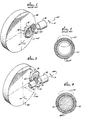
- FIGURE 1 is a diagrammatic illustration showing a conventional face mill generation of a spiral bevel gear;
- FIGURE 2 is an axial plan view of a conventional spiral bevel gear;
- FIGURE 3 is a diagrammatic illustration generally similar in view point to Figure 1 but showing the face mill generation of a spiral bevel gear by a method embodying the invention;
- FIGURE 4 is an axial plan view of a spiral bevel gear made by a method embodying the invention;
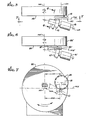
- FIGURES 5 and 6 are diagrammatic side views illustrating the face mill generation of spiral bevel gears respectively by a method embodying the invention and by the conventional method; and
- FIGURE 7 is a diagrammatic view along the line 7-7 of Figure 5 and illustrating certain features of the generation of a spiral bevel gear by said method embodying the invention.
- The formation of a spiral bevel gear by a method embodying the present invention, illustrated in Figures 3-5 and 7, employs a
work piece 10 that begins as a gear blank having ashaft 12 that projects axially from what is to be the toothed face 14 of the finished gear. As best shown in Figure 3, thework piece 10 is mounted on arotatable workhead 16. A gear is to be generated from the blank 10 by the action of arotatable cutter 18, using the face mill generation method. Thecutter 18 is disc-shaped, having a circular array of substantiallyidentical blades 20 disposed about its periphery, these blades, in operation, being caused to engage the work piece sequentially, successively removing additional material from the blank to generate at least one tooth surface. The cutter is mounted on acradle 22 that is in turn rotatable about a machine axis MA, thus producing an orbital motion of the cutter. - The
work piece 10 rotates about a workhead axis WA in the direction of an arrow A, while thecutter 18 rotates in the direction of the arrow B, and thecradle 22 rotates in the direction of the arrow C. As these three rotational movements take place, thework piece 10 andworkhead 16 slowly move forward bringing the work piece into repeated and deeper engagement with thecutter 18. This forward movement can be either continuous or incremental and it results in a groove being cut in the blank 10 to generate a single tooth face. In some situations the spread blade method may be used to simultaneously generate two facing tooth surfaces that define a single valley between two teeth. The rotation of thecradle 22 and the blank 10 must be synchronized to simulate a gear mesh. However, the shape of a tooth 24 generated in this way is independent of the rotational speed of thecutter 18. - It will immediately be recognized that the known and conventional arrangement of machine components, illustrated in Figures 1 and 2, is precluded by the presence of the
shaft 12 which occupies almost the entire central area of the gear or blank 10 surrounded by the teeth 24. (In Figures 1, 2 and 6 corresponding components are identified by the same letters and numbers but with a prime designation). The cutter 18', shown in Figure 1 and the cutter periphery CP' shown in Figure 2 intrude very substantially into this area. - The problem of interference between the
cutter 18 and theshaft 12 is solved, according to the present invention, by radically altering the gear tooth configuration in a most unconventional manner. It will be noted that the teeth 24' of the conventional gear 10' shown in Figure 2 have an arcuate curvature and lie at an angle to the-radii of the gear. The orientation of each tooth 24' is such that the concave surface faces inwardly the center of the gear 10' rather than outwardly away from the center. In other words, a person looking precisely radially at the outer surface of the gear could see only a convex tooth surface. It is generally accepted that in a gear set the concave surfaces of a pinion gear drive the convex surfaces of the driven gear. - In the fully cut
spiral bevel gear 10, shown in Figure 4, of the configuration of this invention, the teeth 24 have a reverse curvature. A person looking precisely radially inwardly toward the periphery of thisgear 10 would see only a concave surface. The convex surfaces face inwardly toward theshaft 12. Preferably this gear would be used in such a way that convex surfaces drive concave surfaces, the opposite of the conventional arrangement. - The method of cutting this
gear 10 is best understood with reference to Figure 5 where it can be seen that cutter axis CA is disposed much further outwardly with respect to thework piece 10 than in the conventional arrangement of Figure 6. In fact, the cutter distance CD exceeds the outer cone distance OCD. The cutter distance CD, sometimes known as the horizontal cutter distance, is in the arrangements illustrated, the radial distance measured perpendicularly from the machine axis MA to the perpendicular projection onto the plane containing the gear blank axis MA and the machine axis MA of the cutter axis CA. The outer cone distance OCD is the radial distance measured perpendicularly from the machine axis MA to the outer edge of the cone of the gear being generated. - Another unusual feature of a gear formed by the method illustrated in Figures 3 to 5 and 7 is that the mean spiral angle MSA is negative. The mean spiral angle MSA is the angle between a pitch cone element PCE and a tangent of a convex tooth face measured at the point where the gear pitch cone element intersects the mean cone distance. The mean cone distance is the mid-point between the inner and lower peripheral edges of the truncated cone having its apex at the machine axis MA and passing through the gear teeth along the pitch cone. In a conventional spiral bevel gear cutting arrangement such as that shown in Figure 6 the spiral angle is always positive or is zero in the extreme case of a zerol gear.
- It will be noted that, as best shown in Figures 3, 4 and 5, the cutter 18.does not intrude into the area occupied by the
shaft 12 as it would if positioned in the conventional manner of the cutter shown in Figures 1, 2 and 6. The gear blank 10 can therefore be fully cut despite the presence of theshaft 12 or any other such integrally formed central structure that protrudes axially from the toothed face of the gear thus generated. The need for a joint between thegear 10 and theshaft 12 is therefore eliminated. - There are unexpected advantages to a reverse curvature spiral bevel gear made by a method embodying the present invention apart from its ease of manufacture. The face contact ratio is higher for a given spiral angle, meaning that more teeth share the load when compared to a conventional gear of the same size. If desired, the spiral angle of the gear can be reduced in comparison to a conventional gear and the face contact ratio thus made equal. With a reduced spiral angle, smaller, lighter bearings can be used.
- There are limitations associated with the gears made by the described method embodying the invention. It will be observed that the maximum diameter of a gear that can be cut by a given machine is reduced. Care must be taken to ensure that the cutter does not intrude into the blank as the blades continue on their circular path after cutting the tooth. This potential intrusion, which must be avoided, is a function of gear blank size, tooth depth, cutter diameter and spiral angle.
- On balance it will be found that the present invention is particularly useful in those situations in which gears with shafts or other central structures protruding from their toothed surfaces must withstand high loads with a high degree of reliability. In addition the cost of manufacturing and assembling the joint is avoided. There is also a considerable weight saving, which is particularly important in aircraft applications.
- While a particular form of the invention has been illustrated and described, it will be apparent that various modifications can be made without departing from the scope of the invention as defined by the attached claims.
Claims (3)
Applications Claiming Priority (2)
| Application Number | Priority Date | Filing Date | Title |
|---|---|---|---|
| US06/396,026 US4518287A (en) | 1982-07-07 | 1982-07-07 | Method of face mill generation of spiral bevel gears with integral central structure and resulting product |
| US396026 | 1982-07-07 |
Publications (2)
| Publication Number | Publication Date |
|---|---|
| EP0099041A1 EP0099041A1 (en) | 1984-01-25 |
| EP0099041B1 true EP0099041B1 (en) | 1986-10-01 |
Family
ID=23565531
Family Applications (1)
| Application Number | Title | Priority Date | Filing Date |
|---|---|---|---|
| EP83106497A Expired EP0099041B1 (en) | 1982-07-07 | 1983-07-04 | Method of face mill generation of spiral bevel gears with integral central structure and resulting product |
Country Status (10)
| Country | Link |
|---|---|
| US (1) | US4518287A (en) |
| EP (1) | EP0099041B1 (en) |
| JP (1) | JPS5993223A (en) |
| KR (1) | KR910006209B1 (en) |
| AU (1) | AU559909B2 (en) |
| BR (1) | BR8303619A (en) |
| CA (1) | CA1199208A (en) |
| DE (1) | DE3366583D1 (en) |
| IL (1) | IL69163A (en) |
| ZA (1) | ZA834983B (en) |
Families Citing this family (16)
| Publication number | Priority date | Publication date | Assignee | Title |
|---|---|---|---|---|
| DE3680086D1 (en) * | 1985-12-13 | 1991-08-08 | Oerlikon Buehrle Ag | METHOD FOR GRINDING THE TOOTHING OF BEVEL GEARS WITH LONG-BENDED TEETH AND TOOL AND DEVICE FOR IMPLEMENTING THE METHOD. |
| US6146253A (en) * | 1996-04-23 | 2000-11-14 | Mcdonnell Douglas Helicopter Company | Apparatus and method for precision grinding face gear |
| US5823857A (en) * | 1996-04-23 | 1998-10-20 | Mcdonnell Douglas Helicopter Company | Apparatus and method for precision grinding of face gears |
| US5862706A (en) * | 1996-07-16 | 1999-01-26 | Mcdonnell Douglas Helicopter Company | Shaft deflection controller |
| US5823470A (en) * | 1996-07-16 | 1998-10-20 | Mcdonnell Douglas Helicopter Co. | Split torque proprotor transmission |
| US5802918A (en) * | 1996-10-16 | 1998-09-08 | Mcdonnell Douglas Helicopter Co. | Concentric face gear transmission assembly |
| US6129793A (en) * | 1997-08-11 | 2000-10-10 | Tan; Jie | Face-gear forging method |
| DE19826067B4 (en) * | 1998-06-12 | 2007-11-22 | Zf Friedrichshafen Ag | Transmission for a steerable drive wheel of a material handling vehicle |
| US6935817B2 (en) * | 2002-08-14 | 2005-08-30 | Pratt & Whitney Canada Corp. | Airfoil machining using cup tool |
| EP1627158B1 (en) * | 2003-05-28 | 2014-05-07 | The Boeing Company | Torque dividing gear drive system and method of driving an output gear |
| DE10352542A1 (en) * | 2003-11-11 | 2005-06-09 | Mtu Aero Engines Gmbh | Milling tool and method for milling recesses |
| US20080016880A1 (en) * | 2006-07-24 | 2008-01-24 | Vittorio Bruno | Gas turbine starter gear shaft and method of manufacture |
| JP5132753B2 (en) * | 2010-11-10 | 2013-01-30 | 株式会社稲坂歯車製作所 | Tooth surface processing method for curved bevel gears |
| EP2535134B1 (en) * | 2011-06-16 | 2018-01-24 | Klingelnberg AG | Method for pre-toothing multiple different bevelled wheels |
| US9033625B2 (en) * | 2011-08-08 | 2015-05-19 | The Gleason Works | Bevel gear manufacture with face cutters without swing axis motion |
| CN109812544B (en) * | 2019-02-03 | 2022-04-19 | 南昌航空大学 | Arc tooth surface gear transmission pair and design method |
Family Cites Families (11)
| Publication number | Priority date | Publication date | Assignee | Title |
|---|---|---|---|---|
| US1376600A (en) * | 1921-05-03 | Gear-cutting- machine | ||
| US1656506A (en) * | 1923-07-03 | 1928-01-17 | Security Trust Company | Machine for cutting gear teeth |
| US1655076A (en) * | 1926-01-27 | 1928-01-03 | Gleason Works | Method of and apparatus for producing gears |
| US2342232A (en) * | 1940-03-19 | 1944-02-22 | Gleason Works | Method and machine for producing gears |
| US2783686A (en) * | 1951-09-29 | 1957-03-05 | Fiat Spa | Hypoid gear cutting |
| DE1084549B (en) * | 1955-01-19 | 1960-06-30 | Gleason Works | Rolling process for generating gear wheel flanks, in particular on conical and hyperboloid wheels with a large cone distance, and a machine designed to carry out the process |
| US2932923A (en) * | 1958-03-05 | 1960-04-19 | Gleason Works | Machine for generating gears |
| CH417284A (en) * | 1963-01-07 | 1966-07-15 | Oerlikon Buehrle Holding Ag | Method and cutter head pair for longitudinally crowned toothing of a bevel gear or hypoid gear pair with longitudinally curved teeth |
| US3213756A (en) * | 1963-09-26 | 1965-10-26 | Gleason Works | Gear machine and indexing mechanism therefor |
| CH590103A5 (en) * | 1975-03-27 | 1977-07-29 | Oerlikon Buehrle Ag | |
| US3971293A (en) * | 1975-04-30 | 1976-07-27 | The Gleason Works | Anti-backlash mechanism for generating train of gear cutting machine |
-
1982
- 1982-07-07 US US06/396,026 patent/US4518287A/en not_active Expired - Lifetime
-
1983
- 1983-06-24 CA CA000431128A patent/CA1199208A/en not_active Expired
- 1983-06-29 AU AU16388/83A patent/AU559909B2/en not_active Ceased
- 1983-07-04 DE DE8383106497T patent/DE3366583D1/en not_active Expired
- 1983-07-04 EP EP83106497A patent/EP0099041B1/en not_active Expired
- 1983-07-05 IL IL69163A patent/IL69163A/en not_active IP Right Cessation
- 1983-07-06 KR KR838303082A patent/KR910006209B1/en not_active Expired
- 1983-07-07 ZA ZA834983A patent/ZA834983B/en unknown
- 1983-07-07 JP JP58124043A patent/JPS5993223A/en active Pending
- 1983-07-08 BR BR8303619A patent/BR8303619A/en unknown
Also Published As
| Publication number | Publication date |
|---|---|
| IL69163A (en) | 1986-02-28 |
| AU1638883A (en) | 1984-01-12 |
| DE3366583D1 (en) | 1986-11-06 |
| IL69163A0 (en) | 1983-11-30 |
| US4518287A (en) | 1985-05-21 |
| KR840005374A (en) | 1984-11-12 |
| JPS5993223A (en) | 1984-05-29 |
| BR8303619A (en) | 1984-02-14 |
| EP0099041A1 (en) | 1984-01-25 |
| AU559909B2 (en) | 1987-03-26 |
| CA1199208A (en) | 1986-01-14 |
| KR910006209B1 (en) | 1991-08-17 |
| ZA834983B (en) | 1984-03-28 |
Similar Documents
| Publication | Publication Date | Title |
|---|---|---|
| US4518287A (en) | Method of face mill generation of spiral bevel gears with integral central structure and resulting product | |
| CA2161782C (en) | Method of dressing a threaded grinding wheel | |
| US5247847A (en) | Cam gear assembly | |
| EP0332450B1 (en) | Double-toothed gear, system for generating its tooth profiles and differential speed reduction apparatus using it | |
| JP5423460B2 (en) | Oscillating gear machining method and machine | |
| EP0559798B1 (en) | Tool for producing crown wheels, and method for producing such a tool | |
| WO1999051890A1 (en) | Face gearing with conical involute pinion | |
| US4174914A (en) | Spherical hob for generating gears | |
| JPS631472B2 (en) | ||
| US8205518B2 (en) | Pinion meshing with a given face gear in accordance with altered design parameters | |
| US6840722B1 (en) | Machining apparatus and machining method | |
| JPS61159323A (en) | Method of machining tooth of gear by rotating gear-shaped tool | |
| JP5423461B2 (en) | Machining method of oscillating gear | |
| US4467567A (en) | Method of crown grinding gears having lengthwise curved teeth | |
| NL9300617A (en) | Method for manufacturing a crown wheel. | |
| EP3043944B1 (en) | Method of machining an internal bevel gear | |
| JP2715079B2 (en) | High-precision rotary indexing device | |
| US5622459A (en) | Tool for manufacturing crown wheels | |
| US2861502A (en) | Devices for cutting and generating hypocycloidal gears | |
| RU2220039C2 (en) | Apparatus for abrasive working of flat surfaces | |
| JP3598117B2 (en) | How to send a tool | |
| EP0323868A1 (en) | Process for producing a crown wheel | |
| EP0007318A1 (en) | Constant velocity universal joint | |
| US2505269A (en) | Method of producing gears | |
| SU887090A1 (en) | Method of cutting cone toothed gears |
Legal Events
| Date | Code | Title | Description |
|---|---|---|---|
| PUAI | Public reference made under article 153(3) epc to a published international application that has entered the european phase |
Free format text: ORIGINAL CODE: 0009012 |
|
| AK | Designated contracting states |
Designated state(s): AT BE CH DE FR GB IT LI LU NL SE |
|
| 17P | Request for examination filed |
Effective date: 19840712 |
|
| GRAA | (expected) grant |
Free format text: ORIGINAL CODE: 0009210 |
|
| AK | Designated contracting states |
Kind code of ref document: B1 Designated state(s): BE DE FR GB IT LU NL |
|
| ITF | It: translation for a ep patent filed | ||
| REF | Corresponds to: |
Ref document number: 3366583 Country of ref document: DE Date of ref document: 19861106 |
|
| ET | Fr: translation filed | ||
| PLBE | No opposition filed within time limit |
Free format text: ORIGINAL CODE: 0009261 |
|
| STAA | Information on the status of an ep patent application or granted ep patent |
Free format text: STATUS: NO OPPOSITION FILED WITHIN TIME LIMIT |
|
| 26N | No opposition filed | ||
| ITTA | It: last paid annual fee | ||
| EPTA | Lu: last paid annual fee | ||
| PGFP | Annual fee paid to national office [announced via postgrant information from national office to epo] |
Ref country code: GB Payment date: 19970625 Year of fee payment: 15 |
|
| PGFP | Annual fee paid to national office [announced via postgrant information from national office to epo] |
Ref country code: FR Payment date: 19970709 Year of fee payment: 15 |
|
| PGFP | Annual fee paid to national office [announced via postgrant information from national office to epo] |
Ref country code: DE Payment date: 19970714 Year of fee payment: 15 |
|
| PGFP | Annual fee paid to national office [announced via postgrant information from national office to epo] |
Ref country code: NL Payment date: 19970731 Year of fee payment: 15 |
|
| PGFP | Annual fee paid to national office [announced via postgrant information from national office to epo] |
Ref country code: LU Payment date: 19970814 Year of fee payment: 15 |
|
| PGFP | Annual fee paid to national office [announced via postgrant information from national office to epo] |
Ref country code: BE Payment date: 19970828 Year of fee payment: 15 |
|
| PG25 | Lapsed in a contracting state [announced via postgrant information from national office to epo] |
Ref country code: LU Free format text: LAPSE BECAUSE OF NON-PAYMENT OF DUE FEES Effective date: 19980704 Ref country code: GB Free format text: LAPSE BECAUSE OF NON-PAYMENT OF DUE FEES Effective date: 19980704 |
|
| PG25 | Lapsed in a contracting state [announced via postgrant information from national office to epo] |
Ref country code: BE Free format text: LAPSE BECAUSE OF NON-PAYMENT OF DUE FEES Effective date: 19980731 |
|
| BERE | Be: lapsed |
Owner name: WESTERN GEAR CORP. Effective date: 19980731 |
|
| PG25 | Lapsed in a contracting state [announced via postgrant information from national office to epo] |
Ref country code: NL Free format text: LAPSE BECAUSE OF NON-PAYMENT OF DUE FEES Effective date: 19990201 |
|
| GBPC | Gb: european patent ceased through non-payment of renewal fee |
Effective date: 19980704 |
|
| PG25 | Lapsed in a contracting state [announced via postgrant information from national office to epo] |
Ref country code: FR Free format text: LAPSE BECAUSE OF NON-PAYMENT OF DUE FEES Effective date: 19990331 |
|
| NLV4 | Nl: lapsed or anulled due to non-payment of the annual fee |
Effective date: 19990201 |
|
| PG25 | Lapsed in a contracting state [announced via postgrant information from national office to epo] |
Ref country code: DE Free format text: LAPSE BECAUSE OF NON-PAYMENT OF DUE FEES Effective date: 19990501 |
|
| REG | Reference to a national code |
Ref country code: FR Ref legal event code: ST |