EP0098733A2 - Egg processing system - Google Patents
Egg processing system Download PDFInfo
- Publication number
- EP0098733A2 EP0098733A2 EP83303751A EP83303751A EP0098733A2 EP 0098733 A2 EP0098733 A2 EP 0098733A2 EP 83303751 A EP83303751 A EP 83303751A EP 83303751 A EP83303751 A EP 83303751A EP 0098733 A2 EP0098733 A2 EP 0098733A2
- Authority
- EP
- European Patent Office
- Prior art keywords
- eggs
- egg
- receiving station
- conveyor
- conveyor means
- Prior art date
- Legal status (The legal status is an assumption and is not a legal conclusion. Google has not performed a legal analysis and makes no representation as to the accuracy of the status listed.)
- Granted
Links
- 238000012545 processing Methods 0.000 title description 23
- 235000013601 eggs Nutrition 0.000 claims abstract description 291
- 238000012856 packing Methods 0.000 claims description 14
- 238000000034 method Methods 0.000 claims description 11
- 238000004806 packaging method and process Methods 0.000 claims description 4
- 230000007423 decrease Effects 0.000 claims description 3
- 230000001419 dependent effect Effects 0.000 claims description 3
- 230000000694 effects Effects 0.000 claims description 2
- 230000000712 assembly Effects 0.000 description 33
- 238000000429 assembly Methods 0.000 description 33
- 238000005303 weighing Methods 0.000 description 25
- 230000007547 defect Effects 0.000 description 10
- 238000012546 transfer Methods 0.000 description 10
- 230000002950 deficient Effects 0.000 description 8
- 230000002093 peripheral effect Effects 0.000 description 7
- 125000006850 spacer group Chemical group 0.000 description 4
- 230000008878 coupling Effects 0.000 description 3
- 238000010168 coupling process Methods 0.000 description 3
- 238000005859 coupling reaction Methods 0.000 description 3
- 230000008569 process Effects 0.000 description 3
- 229920002799 BoPET Polymers 0.000 description 2
- 239000005041 Mylar™ Substances 0.000 description 2
- 239000004677 Nylon Substances 0.000 description 2
- 239000008280 blood Substances 0.000 description 2
- 210000004369 blood Anatomy 0.000 description 2
- 238000010276 construction Methods 0.000 description 2
- 238000001514 detection method Methods 0.000 description 2
- 229920001778 nylon Polymers 0.000 description 2
- 239000004033 plastic Substances 0.000 description 2
- 238000000926 separation method Methods 0.000 description 2
- 230000000007 visual effect Effects 0.000 description 2
- 230000003213 activating effect Effects 0.000 description 1
- 230000004913 activation Effects 0.000 description 1
- 230000004323 axial length Effects 0.000 description 1
- 230000006835 compression Effects 0.000 description 1
- 238000007906 compression Methods 0.000 description 1
- 230000003247 decreasing effect Effects 0.000 description 1
- 239000012530 fluid Substances 0.000 description 1
- 239000006260 foam Substances 0.000 description 1
- 230000005484 gravity Effects 0.000 description 1
- 230000007246 mechanism Effects 0.000 description 1
- 239000002184 metal Substances 0.000 description 1
- 238000012986 modification Methods 0.000 description 1
- 230000004048 modification Effects 0.000 description 1
- 230000004044 response Effects 0.000 description 1
- 230000002441 reversible effect Effects 0.000 description 1
- 230000001360 synchronised effect Effects 0.000 description 1
Images


Classifications
-
- B—PERFORMING OPERATIONS; TRANSPORTING
- B07—SEPARATING SOLIDS FROM SOLIDS; SORTING
- B07C—POSTAL SORTING; SORTING INDIVIDUAL ARTICLES, OR BULK MATERIAL FIT TO BE SORTED PIECE-MEAL, e.g. BY PICKING
- B07C5/00—Sorting according to a characteristic or feature of the articles or material being sorted, e.g. by control effected by devices which detect or measure such characteristic or feature; Sorting by manually actuated devices, e.g. switches
- B07C5/16—Sorting according to weight
-
- A—HUMAN NECESSITIES
- A01—AGRICULTURE; FORESTRY; ANIMAL HUSBANDRY; HUNTING; TRAPPING; FISHING
- A01K—ANIMAL HUSBANDRY; AVICULTURE; APICULTURE; PISCICULTURE; FISHING; REARING OR BREEDING ANIMALS, NOT OTHERWISE PROVIDED FOR; NEW BREEDS OF ANIMALS
- A01K43/00—Testing, sorting or cleaning eggs ; Conveying devices ; Pick-up devices
-
- B—PERFORMING OPERATIONS; TRANSPORTING
- B07—SEPARATING SOLIDS FROM SOLIDS; SORTING
- B07C—POSTAL SORTING; SORTING INDIVIDUAL ARTICLES, OR BULK MATERIAL FIT TO BE SORTED PIECE-MEAL, e.g. BY PICKING
- B07C5/00—Sorting according to a characteristic or feature of the articles or material being sorted, e.g. by control effected by devices which detect or measure such characteristic or feature; Sorting by manually actuated devices, e.g. switches
- B07C5/36—Sorting apparatus characterised by the means used for distribution
-
- B—PERFORMING OPERATIONS; TRANSPORTING
- B65—CONVEYING; PACKING; STORING; HANDLING THIN OR FILAMENTARY MATERIAL
- B65G—TRANSPORT OR STORAGE DEVICES, e.g. CONVEYORS FOR LOADING OR TIPPING, SHOP CONVEYOR SYSTEMS OR PNEUMATIC TUBE CONVEYORS
- B65G2207/00—Indexing codes relating to constructional details, configuration and additional features of a handling device, e.g. Conveyors
- B65G2207/42—Soft elements to prevent damage to articles, e.g. bristles, foam
Definitions
- This invention relates generally to an egg processing system in which eggs are graded and classified and subsequently separated and packaged at a plurality of receiving stations according to their individual physical characteristics, including weight.
- egg processing systems in which eggs having the same size, weight, etc. are delivered to - separate receiving stations for packing into egg cartons according to their individual physical characteristics are known in the art. See, for example, U.S. Patent Nos. 3,224;580 and 3,255,660.
- an egg grader by means of which each of the eggs being processed is classified or graded in accordance with its particular physical characteristics, including the weight or size of the egg.
- a candling operation included in the egg grading process is included in the egg grading process by which defects such as blood spots, cracks and the like are identified.
- each egg is weighed in order to determine its size for ultimate packing with other eggs of a generally similar weight and size.
- the eggs are weighed in order to facilitate packing in accordance with established weight ranges specified by governmental agencies.
- Eggs are generally classified into designated classifications, dependent on weight, such as small, medium, large and extra large.
- classifications such as peewee and jumbo are utilized for those eggs not falling within the aforementioned weight classifications.
- an apparatus for transferring eggs continuously conveyed in spaced-apart, aligned relationship by a first conveyor means to a receiving station at which the eggs are packaged according to their physical characteristics.
- the apparatus includes means, disposed adjacent to the conveyor means at the receiving station and movable with respect to the receiving station, for releasing eggs having the same physical characteristics from the conveying means in a predetermined sequence at the receiving station. Also included are means, coupled to the releasing means, for varying the position of the releasing means with respect to the receiving station according to the speed of the conveyor means.
- the foregoing objects of the present invention are also achieved in a method of transferring eggs delivered to a receiving station of an egg grading apparatus at which the eggs are packaged according to their individual physical characteristics from first conveyor means to the receiving station.
- the method comprises the steps of continuously conveying the eggs in spaced-apart, aligned relationship to the receiving station on the first conveyor means, and releasing eggs having the same physical characteristics from the first conveyor means in a predetermined sequence at the receiving station,-and varying the position with respect to the receiving station at which the eggs are released according to the speed at which the eggs are conveyed to the receiving station by the conveyor means.
- an egg processing system including an incoming conveyor 1 and a preloader 2 by which a mass of eggs to be processed are loaded.
- the eggs are conveyed from the preloader on a conveyor 3 to an egg washer 4 in which the eggs are washed.
- the egg washer is disposed adjacent a candler 10 to which the eggs are conveyed and in which defects are visually detected by an operator who stands on a platform on either side of the candler.
- the eggs are conveyed through candler 10 by means of a movable spool bar conveyor 7 (see FIG. 2) to an egg weighing station 19 at which the eggs are individually weighed.
- the eggs After weighing, the eggs are conveyed in spaced-apart, adjacent pairs by means of a conveyor 21 to a plurality of egg packers 22 at which eggs which have been graded and classified are separated according to their individual physical characteristics. Cartons into which the eggs are packed are conveyed to each of the packers by means of conveyors 8 and 9 which extend beneath conveyor 21 and individual egg conveyors 5 which lead to each of packers 22.
- the egg candler of the egg processing system is generally identified by reference numeral 10.
- a mass of eggs 11, including randomly dispersed eggs having defects such as blood spots, dirt stains, rough spots, shell cracks and the like, are continuously conveyed by a spool bar conveyor including a plurality of spool bars 12 over a high-intensity light source to enable the visual detection of such defects by an operator standing adjacent to the conveyor.
- the eggs are aligned in six parallel longitudinal columns on the spool bars for passage through the candler and over the high-intensity light source to enable visual detection of defects.
- two such conveyors may be disposed adjacent one another to provide a twelve column conveyor for conveying the eggs through the candler.
- An elongated movable pointer or rod 13 is disposed vertically above spool bars 12 and is pivotably mounted at its upper end so as to be movable over a selected area or plane of the candler above the spool bars 12 in mutually orthogonal directions (indicated by arrows 14 and 15), approximately parallel to the longitudinal axis 16 of the spool bar conveyor and perpendicular to longitudinal axis 16, i.e., in directions approximately parallel to the columns and rows of eggs 11 on spool bars 12.
- the vertical lower end 17 of pointer 13 is disposed adjacent spool bars 12 and is axially movable along its longitudinal axis 18 so that lower end 17 is movab-le into and out of engagement with the shells of eggs disposed in the plurality of locations within the selected area of the candling system on spool bars 12 over which pointer 13 is movable.
- the eggs, including defective eggs identified by the operator, are conveyed through the candler to an egg weighing station 19 (see FIG.
- pointer 13 is pivotably mounted in a frame 23 which is mounted on a longitudinal support beam 24 over the spool bars 12 (FIG. 3).
- the frame 23, which may be either stationary or movable, includes a first axle 25 rotatably mounted in frame 23 and disposed in a direction perpendicular to the longitudinal axis of the spool bar conveyor.
- Another frame 26 is rigidly mounted on axle 25 so as to be pivotable about the longitudinal axis thereof and includes a second axle 27, which is coupled to pointer 13 by means of a rectangular-shaped frame member 28 rigidly mounted on axle 27.
- Axle 27 is rotatably mounted in frame 26 in a direction parallel to the longitudinal axis of the spool bar conveyor.
- Frame member 28 includes an aperture 29 having a diameter slightly greater than that of pointer 13 through which pointer 13 passes.
- the pointer has a flange 30 disposed at its vertically uppermost end which engages one end of a coil spring 31 disposed over the pointer between flange 30 and frame 28 for movably supporting rod 13 in frame 28, and in frames 23 and 26.
- This arrangement permits the movement of pointer 13 in the mutually orthogonal directions 14 and 15 parallel and transversely with respect to the longitudinal axis of the spool bar conveyor, as well as longitudinally along axis 18 of pointer 13 into and out of engagement with eggs 11 on spool bars 12.
- Pointer 13 includes means for generating at least one signal for indicating the position of eggs 11 having a defect on spool bars 12 when the shells of the eggs are engaged by pointer 13.
- this signal generating means comprises potentiometers 32 and 33 coupled by a plurality of intermeshing gear wheels 34 and 35 to axles 25 and 27 mounted in frames 23 and 26.
- Potentiometer 32 is rigidly mounted on frame 23, and potentiometer 33 is rigidly mounted on frame 26, along with gear wheels 34 and 35, respectively.
- the signal generating means further comprises a switch, generally identified by reference numeral 36, disposed in the vertically lower end 17 of pointer 13.
- the switch comprises a cylinder slidably disposed within the lower end of the pointer having an elongated portion 37 extending from an aperture provided in the lower end of the pointer for engaging the shells of the eggs disposed on spool bars 12.
- An air pressure supply source and pneumatic switch (not shown) are coupled to the interior of pointer 13.
- the pneumatic switch is also electrically coupled to potentiometers 32 and 33.
- Another aperture 38 is disposed at the vertical lower end of pointer 13 in the side wall thereof adjacent the cylinder of switch 36 so that when the cylinder is disposed in its lowermost position in pointer 13 and elongated portion 37 extends from the lower end of the pointer, aperture 38 is uncovered and the pressurized air supply to the interior of the pointer is permitted to escape.
- portion 37 of switch 36 engages an egg and the cylinder is pushed upwardly within pointer 13
- aperture 38 is covered by the cylinder and the air is not permitted to escape, thus increasing air pressure within the pointer and activating the pneumatic switch.
- the signal generating means also comprises means for generating a second signal approximately simultaneously with generation of the first signal for identifying the type of defect detected in the eggs engaged by pointer 13.
- This signal generating means comprises manually- operable pneumatic switches (not shown) which are coupled at one end to a pressurized air supply source and at the other end directly by tubular conduits extending through the interior of the pointer to two additional apertures 39 and 40 disposed in the lower end of pointer 13. These apertures are disposed directly above aperture 38 and are manually closable by placing a finger over the apertures.
- eggs 11 are continuously conveyed on spool bars 12 beneath rod 13 over the light source of candler 10 and are visually inspected by an operator for defects. If defective eggs are detected by the operator, pointer 13 is first pivoted to a position over each defective egg and then is moved downwardly, along the longitudinal axis of the pointer, toward the defective egg until the egg is engaged by extended portion 37 of switch 36. At the same time, the operator places a finger over one or both of apertures 39 and 40, or alternatively, leaves both of the apertures open.
- pointer 13 Since pointer 13 is mounted by means of spring 31 on frame 28, after the operator engages a defective egg, the pointer retracts to a position away from the eggs on'spool bars 12 to a position in which it is ready to be used to identify the location . of another defective egg.
- Holding bar 41 is in the form of a U-shaped channel having a recessed section 42 at which the egg, after passing through candler 10, is positioned.
- the egg is fed from candler 10 by the rotating spools and is gravity fed along the inclined surface of holding bar 41 into the recessed egg receiving section 42.
- a series of six holding bars 41 are disposed adjacent one another, such that six eggs may be fed simultaneously from the six columns of eggs on the spool bar conveyor of candler 10 to a plurality of weighing stations 43 disposed adjacent the end of the receiving sections 42.
- the eggs are transferred to the egg conveyor from the weighing stations by the simultaneous transfer of six pairs of eggs as is described later herein.
- other multiples of bars may be provided in accordance with the invention, e.g., twelve bars to transfer twenty-four eggs from the weighing stations to the egg conveyor if two six-column conveyors are used in the candler.
- each weighing station 43 Located downstream of holding bar 41 is the weighing station 43.
- Each weighing station 43 has a contoured upper section having a recess 44 adapted to hold an egg and formed between the upwardly protruding prongs 45.
- Weighing station 43 includes a scale which is movable in a vertical direction and serves to determine accurately the weight of each egg as it is positioned thereon.
- the weight of each egg as determined at weighing station 43 is represented by an electrical signal generated by the scale and which is then, for example, stored in a memory device, such as a random access memory, associated with a central processor unit.
- Downstream of weighing station 43 is a pick-up station 46 which has provision for holding two eggs in a pair of recesses 47 and 48.
- An egg advancing means illustrated as a bar 49, includes an upper horizontal section 50 formed by spaced-apart side members 51 and 52 each of which has three recesses 53, 54 and 55 for holding individual eggs.
- a main drive motor drives a sbaft 56 (see FIG. 14) which in turn is connected to the right angle gear box 57 by drive chain 58, the output gear box 57 driving chain member 59.
- a pair of oppositely disposed crank members 60 are rotationally driven by chain 59 and pivotally connected to the downwardly depending arm 61 of the egg-advancing means 49.
- crank members 62 are similarly driven by chain 59 and pivotally connected by way of linkage 63 to the downwardly depending arm 61 of the egg-advancing bar 49.
- the upper horizontal section 50 is driven in an elliptical or oval path such that the portion of the path between the holding station 41, weighing station 43 and pick-up station 46 is along the major axis of the elliptical path.
- a second egg is then rolled down the inclined portion of holding station 41 into recessed section 42.
- the egg is lifted from the weighing station 43 and advanced to recess 47 at pick-up station 46 (FIG. 11).
- the egg is advanced again by advancing bar 49 into recess 48 of pick-up station 46 (FIG. 12).
- a lifting arm 64 which move both rotationally with respect to pick-up station 46 as well as in a direction longitudinally with respect thereto (FIG. 13).
- the longitudinal movement of the lifting arm 64 with respect to pick-up station 46 serves to move the lifted eggs away from pick-up station 46 as the advancing means 49 is moving a subsequent egg into the recesses 47 and 48.
- a main drive motor is coupled to drive shaft 56 which has mounted thereon a differential speed cam 65 and sprocket-driven chains 58 and 66.
- Chain 58 provides the drive for advancing bar 49 (FIG. 7).
- Chain 66 which is driven by sprocket 67, in turn serves to drive a pair of differential speed-drive sprockets 68 and 69.
- Each of the sprockets 68 and 69 drives the respective shafts 70 and 71 in a counterclockwise direction, the shafts having mounted on the ends thereof crank arms 72 and 73, respectively.
- Each rotary crank arm 72 and 73 is fastened to an elongated support bar 74 on which twelve (12) individual lifting plates, which form lifting arm 64, are mounted, each adjacently spaced pair of lifting plates serving to lift an egg.
- Support bar 74 thus facilitates the simultaneous lifting of two rows of six side-by-side eggs.
- the adjacently spaced lifting plates serve to lift simultaneously twelve (12) eggs from the six pick-up stations 46 provided in the egg grader and transfer the eggs in adjacent pairs to the egg conveyor.
- a cam 75 is mounted at the end of main drive shaft 56 and is engaged by a cam follower 76 mounted on a pivotable arm 77 which in turn is connected at the end thereof to a connecting linkage 78.
- Linkage 78 is pivotally connected to a right-angle drive arm 79 which in turn drives a coupling bar 80 with an oscillating motion about a shaft 81.
- a drive bar 82 is reciprocally driven in a direction toward and away from pick-up stations 46 by means of coupling bar 80 which is connected thereto via a pin 83 slidably mounted in a slot 84.
- Cam 65 is in rotational engagement with a cam follower 85 mounted on an arm 86 which has mounted at its upper end an idler 87 and at its lower end is pivotally connected by a shaft 88 to pivotable arm 77.
- Chain 66 is further routed over idler sprocket 89 which in turn is mounted to an idler arm 90 fastened to a spring 91.
- the spring loaded idler arm 90 serves to maintain tension in the drive chain 66 while support bar 74 is driven both rotationally and longitudinally with respect to pick-up stations 46.
- differential speed cam 65 serves to regulate the rotational drive speed of lifting arm 64 such that when the plates of the arm arrive at the pick-up stations 46 (when the eggs are being removed therefrom), the rotational speed of the lifting arm is decreased to facilitate the smooth upward lifting of the egg from the pick-up stations.
- FIG. 15 in which the rotational movement of the crank arm 72 and lifting arm 64 is illustrated.
- the plates of lifting arm 64 engage the eggs from the underside thereof at pick-up stations 46, which are positioned in the rotational path of arm 64 at approximately the nine o'clock position.
- Arm 64 is then rotated clockwise while also being moved longitudinally away from pick-up stations 46.
- At the twelve o'clock position each of the eggs is brought within the depending arms of carriage assemblies 92 which are part of the egg conveyor and are driven by a chain 93. At this position, both the eggs and carriage assembly should be traveling at the same speed to properly effect transfer.
- each carriage assembly 92 includes a sheet metal platform 94 which has mounted thereon a pair of depending prongs or egg-engaging members 95.
- Prongs 95 are pivotally mounted and positioned opposite one another in order to engage an egg therebetween across its smaller side or width.
- the lower portion of each prong 95 is curved so as to approximate the curvature across the smaller width of the egg, and the upper portion of each prong is reversely bent so as to provide a surface having a generally horizontal orientation.
- the reversely-bent portion of each prong is mounted on a fixed shaft 96 so as to be pivotally movable with respect thereto.
- the prongs are mounted over shaft 96 with the reversely bent portions thereof disposed in opposing relationship.
- a mounting shaft 97 is positioned on the platform 94 generally perpendicular with respect to the fixed shafts 96.
- Cam members 98 have a generally square profile and are pivotally mounted on shaft 97 with the operative bottom flat surface being in engagement with the horizontal surface of reversely-bent portions of egg-engaging prongs 95.
- An integral spacer 99 is disposed between adjacent cam members 98 in order to maintain the proper spacing and engagement of the horizontal cam- engaging surface with the horizontal surface of egg-engaging prongs 95.
- each end of cam members 98 is an extension bar 100 which is spaced from the end cam member 98 by integral spacer 101.
- Bar 100 is provided with an upper T-shaped portion 102 which is engageable with the latch pins of a comb assembly and solenoid-actuated plungers described later herein, in order to cause rotational movement thereof.
- Each bar 100 is fastened or directly coupled to the adjacent spacer 101, cam 98, intermediate spacer 99 and the adjacent cam 98. In this manner, each pair of egg-engaging prongs 95 is operable independently of the others although mounted to a common shaft 97.
- Lifting arm 64 rotates about an axis offset from the line formed between holding stations 41, weighing stations 43 and pick-up stations 46 so that each pair of eggs disposed at pick-up stations 46 is engaged from the underside thereof when the lifting arm 64 reaches approximately a nine o'clock position (looking from the rear of the machine).
- reciprocating drive bar 82 moves the lifting arm assembly away from stations 46 so as to avoid any collision between the eggs being removed from the pick-up stations and the eggs being advanced thereto.
- a comb assembly 103 (FIG. 21) is positioned in the path of the lower surface 118 of the extension bars 100.
- Each carriage assembly 92 arrives at comb assembly 103 with bar 100 in the position depicted in FIG. 18, i.e., in its open position ready to receive the eggs.
- Comb assembly 103 consists of two elongated bar members 104 and 105 disposed adjacent to the travel path 106 of the carriage assemblies on the egg conveyor and on which a plurality of inwardly directed latch pins 107 are disposed.
- the bar members are mounted on a pair of U-shaped, downwardly-extending support members 108 and 109 which are in turn connected to a pair of rotatable rods 110 and 111.
- the rods are connected by means of a linkage 112 to a crank arm 113 and a cam follower 114 mounted at the end of the crank arm which engages a cam 115 mounted on a shaft 116 driven by a chain and sprocket drive assembly 117 which is connected to shaft 56 coupled to the main drive motor.
- the comb assembly includes twelve latch pins 107 for engaging the lower surface 118 of twelve extension bars 100 of the carriage assemblies for closing twelve pairs of prongs on twelve eggs simultaneously during operation of the conveyor.
- egg-engaging prongs 95 are in an open position when passed adjacent the path of the rotating lifting arm 64.
- each carriage assembly 92 arrives at the comb assembly with bars 100 in the position depicted in FIG. 18.
- the latch pins of the comb assembly 103 are positioned in the path of extension bars 100.
- Comb assembly 103 closes or latches prongs 95 on twelve eggs simultaneously.
- Each prong of comb assembly 103 engages a'lower surface 118 of extension bars 100 (FIG. 18) causing the same to rotate in a clockwise direction while rotating cam members 98 therewith.
- Cams 98 are rotated- rotating cam members 98 therewith.
- Cams 98 are rotated approximately 45 such that the ahgular or corner portion thereof downwardly depresses a horizontal surface 119 of the egg-engaging prongs 95 (FIG. 17).
- the downward movement of the generally horizontal cam- engaging surface causes the lower egg-engaging portion of prongs 95 to move inward with respect to one another and close in an engaging relationship with the egg.
- the egg is lifted from lifting arm 64 by the prongs and conveyed to the receiving stations downstream in the machine.
- bars 100 are pivotally moved into the closed position illustrated in FIG. 20, the lower portions 120 thereof engage platform 94 which in turn limits the rotational movement thereof.
- the receiving stations of the egg processing system receive eggs carried in adjacent pairs by carriage assemblies 92.
- the carriage assemblies 92 convey the eggs in spaced-apart, side-by-side pairs to the receiving stations and are coupled to common chain members 93 on each side of the conveyor which drive the carriage assemblies.
- a movable frame 121 (see FIG. 22) on which a plurality of solenoids 123, which activate plungers 124, are mounted, is slidably disposed on rails 125 located adjacent the chain members 93.
- the frame is coupled to a hydraulic cylinder 126 by means of an extension rod 127.
- a compression spring 128 is disposed over rod 127 and engages a stationary guide member 129 mounted on the rod at one end and a circular collar 130 mounted on the rod in spaced-apart relationship with respect to member 129 at its other end.
- the extension rod is rigidly coupled to frame 121 by means of another circular collar member 131.
- - Cylinder 126 is coupled by a hydraulic pressure line 132 to a hydraulic pump 133 which is driven by a stepping motor 134 which also serves as the main drive motor for the egg conveyor.
- Movable frame 121 is disposed over a pair of rotatable resilient cylinders 135 which are coaxially mounted on spaced drive shafts 136.
- the cylinders comprise cylindrical brushes preferably fabricated with nylon bristles.
- a plurality of rotatable disks 137 are mounted on shafts 136 in order to define a plurality of channels in the cylinders for receiving eggs from the carriage assemblies.
- the cylinders are disposed vertically below movable frame 121 and carriage assemblies 92 and have their peripheral ends engaging and in slight interference with those of the adjacent cylinder.
- the peripheral end of the forwardmost cylinder is further disposed in a generally contiguous relationship with an elongated, flexible support member 138, which may comprise a sheet of plastic, such as mylar, stretched over and mounted on a frame extending axially along substantially the entire length of the cylinders.
- a conveyor belt 141 which may comprise a wire conveyor or a plurality of elongated strand members moving axially along the length of the conveyor, is disposed below the cylinders for conveying eggs received therefrom to an egg packer (not shown) which packs the eggs in cartons or trays as desired.
- Conveyor belt 141 is divided into a plurality of channels aligned with those formed in the cylinders by disks 137 by means of a plurality of elongated stationary guide members 142 (FIG. 23) which, in the illustrated embodiment of the invention, are disposed over the conveyor belt in close proximity thereto and have an inverted, V-shaped profile (i.e., are upwardly convex).
- Suitable drive means such as an electric motor, is coupled to shafts 136 for rotating the cylinders so that the peripheral edges thereof rotate in opposite directions inwardly towards each other and downwardly and away from carriage assemblies 92, i.e., in a counterclockwise direction.
- FIG. 23 elongated stationary guide members 142
- support member 138 is upwardly inclined toward the rearwardmost shaft 136 with respect to the direction of movement of conveyor 141 and its uppermost surface 144 is disposed beneath and slightly spaced from the peripheral ends of cylinders 135.
- This surface may also be curved in a direction substantially in conformance with that of the forwardsost one of the cylinders in order to maintain contact between cylinders 135 and the eggs guided along member 138 onto conveyor 141.
- eggs are carried by the prongs 95 of carriage assemblies 92 as illustrated in FIGS. 25 and 26 until they reach a receiving station of the egg grader.
- solenoids 123 are selectively actuated as described in oopending application U.S.Serial No. 394,161 and corresponding (European Application Ref:23495000/EA915) "Egg Handling System,the disclosure of which is incorporated herein by reference.
- Plungers 124 of solenoids 123 engage the upper T-sections 102 of extension bars 100 and cause the bars to rotate in a counterclockwise direction about shaft 97, thereby releasing the eggs from the carriage assemblies.
- Frame 121 is movable with respect to the cylinders 135 to actommodate variations or changes in the speed of carriage assemblies 92 which may vary during operation, depending upon the speed of the candler and weighing systems of the egg grader. As it varies, the position of frame 121 also varies with respect to cylinders 135 and the channels leading to the packer at each receiving station to compensate for changes in the forward drop trajectory of the eggs being released by prongs 95 at different conveyor speeds to assure that the eggs are received in the channels for which they are intended.
- the speed of stepper motor 134 when the speed of stepper motor 134 is increased by the operator of the system, the speed of assemblies 92 will also increase since the motor drive is coupled to the drive mechanism for the egg conveyor.
- pump 133 is coupled by a.hydraulic line 145 to a valve 146 which is connected by a coupling 147 to hydraulic line 132 and is adjusted so that as the speed of motor 134 and assemblies 92 is increased, the flow of hydraulic fluid from pump 133 is controlled so as to cause hydraulic cylinder 126 to advance frame 121 in a direction opposite to the direction of movement of carriage assemblies 92 to a position sufficient to compensate for the forward trajectory of eggs released at that particular speed.
- the linear distance between frame 121 and prongs 95 of the carriage assemblies carrying the eggs to be released thus becomes effectively shorter.
- cylinder 126 similarly moves frame 121 in the opposite direction, i.e., in the same direction as the direction of movement of the carriage assemblies, to another position sufficient to compensate for the smaller forward drop trajectory of the eggs at the lower speed.
- FIGS. 27-29 illustrate another embodiment of the handling system of the invention in which frame 121 is lb disposed over a single rotatable resilient cylinder 135' mounted on drive shaft 136'.
- a plurality of rotatable disks 137' are also mounted on shaft 136' and define a plurality of channels for receiving eggs from the carriage assemblies 92.
- the cylinder is disposed below frame 121 and carriage assemblies 92 and has its peripheral end disposed generally contiguous and slightly spaced from a plurality of elongated flexible guide members 138', each of which may comprise a sheet of mylar plastic, fixed at one end to a stationary rail 139 disposed adjacent the egg conveyor and at the other end over the vertical lower end of a stationary, rigid, arcuate-shaped support member 140 disposed beneath the lower end of the cylinder.
- Conveyor belt 141 is disposed below the cylinder for conveying eggs received thereon to an egg packer (not shown) which packs the eggs into cartons or trays as desired and is divided into a plurality of channels aligned with the disks 137' by means of a plurality of elongated stationary guide members 142 which are upwardly convex in shape and are suspended over the conveyor belt in close proximity thereto.
- Suitable drive means such as an electric motor, is coupled to shaft 136' for rotating the cylinder so that the peripheral end thereof rotates downwardly and away from carriage assemblies 92, i.e., in a counterclockwise direction.
- guide member 140 has an upper lip 143 disposed below shaft 136' about which cylinder 135' rotates and includes an egg-supporting surface 144' which is disposed beneath and spaced from the peripheral end of the cylinder. This surface is curved in a direction substantially in conformance with that of the cylinder (i.e., parallel thereto) in order to maintain contact between the cylinder and the eggs guided along - members 138' and 140 onto conveyor 141.
- the cylinder may, as previously described, comprise a rotating brush fabricated from nylon bristles. Also other resilient members such as foam, inflatable means or the like may also be utilized.
- eggs are carried by the prongs 95 of carriage assemblies 92 until they reach a receiving station of the egg grader.
- solenoids 123 are selectively actuated as previously described so that plungers 124 of solenoids 123 engage the upper T-sections 102 of extension bars 100 and cause the bars to rotate in a counterclockwise direction about shaft 97, thereby releasing the eggs from the carriage assemblies.
- the eggs then drop downwardly as shown in FIG. 29, and are caught by cylinder 135' and members 138' and 140. More specifically, the eggs are released prior to the receiving station, dependent upon the operating speed of the machine.
- the cylinder then carries the eggs downwardly and outwardly away from carriage assemblies 92 into the channels of conveyor 141.
- plurality of elongated guide members 138' have been illustrated in the drawings, a single elongated sheet member could also be used in conjunction with cylinder 135' to catch and guide the eggs released from the carriage assemblies toward conveyor 141.
- FIG. 30 illustrates another embodiment of the receiving station in which frame 121 is slidably mounted on cylindrical rods 148 and is coupled to an elongated threaded shaft 149 driven by a reversible motor 150.
- the position of the frame 121 with respect to the cylinders'135 is adjusted by energizing motor 150 until it is moved to a predetermined position for a particular motor speed at which the conveyor is to-operate.
- the frame is coupled by a cable 151 to a pulley 152 connected to a main drive motor speed control 153 which controls the motor which drives the egg conveyor.
- Speed control 153 may comprise any suitable device for controlling the speed of a motor, such as a potentiometer, shaft encoder or the like. In other respects, the operation of this embodiment of the invention is the same as those previously described.
- release of the eggs from the carriage assemblies is selectively controlled so as to drop the eggs successively into the channels formed by disks 137 and 137' in cylinders 135 and 135' and members 142 on conveyor 141 beginning with the first such channel reached by the eggs as they are conveyed by carriage assemblies 92 to the receiving station. Sequences which may be used for six, five and four channels, respectively, are illustrated in the drawing.
- all eggs which have been determined to have identical or similar physical characteristics are preferably dropped in the channels at one receiving station in the sequence illustrated in FIG. 31.
- egg no. 1 will be dropped in channel A, egg no. 2 in channel B, etc. until all the channels have received an egg, whereupon the process is repeated.
Landscapes
- Life Sciences & Earth Sciences (AREA)
- Environmental Sciences (AREA)
- Animal Husbandry (AREA)
- Biodiversity & Conservation Biology (AREA)
- Wrapping Of Specific Fragile Articles (AREA)
- Sorting Of Articles (AREA)
Abstract
Description
- This invention relates generally to an egg processing system in which eggs are graded and classified and subsequently separated and packaged at a plurality of receiving stations according to their individual physical characteristics, including weight.
- Generally speaking, egg processing systems in which eggs having the same size, weight, etc. are delivered to - separate receiving stations for packing into egg cartons according to their individual physical characteristics are known in the art. See, for example, U.S. Patent Nos. 3,224;580 and 3,255,660. In the processing of eggs, one important component of the processing system is an egg grader by means of which each of the eggs being processed is classified or graded in accordance with its particular physical characteristics, including the weight or size of the egg. Generally, included in the egg grading process is a candling operation by which defects such as blood spots, cracks and the like are identified. In addition, as part of the grading process each egg is weighed in order to determine its size for ultimate packing with other eggs of a generally similar weight and size. In this respect the eggs are weighed in order to facilitate packing in accordance with established weight ranges specified by governmental agencies. Eggs are generally classified into designated classifications, dependent on weight, such as small, medium, large and extra large. In addition, classifications such as peewee and jumbo are utilized for those eggs not falling within the aforementioned weight classifications.
- In an egg grader performing the above functions, limitations are placed on the operation of the machine which in turn dictate the maximum operating speed for an entire automated egg processing system. In order to improve the operating efficiency of such systems, increased demands of higher speed are made on the egg grader which in turn requires egg processing systems having a high-speed response time while maintaining accurate separation and packaging of the respective eggs.
- It is therefore an object of the present invention to provide an improved egg processing system which is capable of grading and classifying and subsequently separating and packaging eggs at one or more receiving stations in the apparatus according to their individual physical characteristics at a high speed of operation.
- It is also an object of the present invention to provide an improved egg processing system which maintains accurate separation and packaging of eggs having the same physical characteristics as the eggs are processed by the system.
- These and other objects of the present invention are achieved in an apparatus for transferring eggs continuously conveyed in spaced-apart, aligned relationship by a first conveyor means to a receiving station at which the eggs are packaged according to their physical characteristics. The apparatus includes means, disposed adjacent to the conveyor means at the receiving station and movable with respect to the receiving station, for releasing eggs having the same physical characteristics from the conveying means in a predetermined sequence at the receiving station. Also included are means, coupled to the releasing means, for varying the position of the releasing means with respect to the receiving station according to the speed of the conveyor means.
- The foregoing objects of the present invention are also achieved in a method of transferring eggs delivered to a receiving station of an egg grading apparatus at which the eggs are packaged according to their individual physical characteristics from first conveyor means to the receiving station. The method comprises the steps of continuously conveying the eggs in spaced-apart, aligned relationship to the receiving station on the first conveyor means, and releasing eggs having the same physical characteristics from the first conveyor means in a predetermined sequence at the receiving station,-and varying the position with respect to the receiving station at which the eggs are released according to the speed at which the eggs are conveyed to the receiving station by the conveyor means.
- These and other novel features and advantages of the present invention will be described in greater detail in the following detailed description.
- FIG. 1 is a top plan view of one embodiment of an improved egg processing system constructed according to the present invention.
- FIG. 2 is a perspective view of the egg processing system illustrated in FIG. 1.
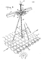
- FIG. 3 is a partial, perspective view of the egg candler of the egg processing system of the present invention.
- FIG. 4 is a partial perspective end view of the egg processing system of the present invention showing the candler, weighing stations, egg transfer system, and egg conveyor.
- FIG. 5 is an enlarged, perspective view of the weighing station of the egg processing system.
- FIG. 6 is an enlarged perspective view, similar to that of FIG. 5, illustrating the egg lifting means of the egg transfer system.
- FIG. 7 is a perspective view of the egg advancing means drive system of the egg transfer system.
- FIG. 8 is an enlarged, elevational view, partially in cross-section, of the egg weighing station depicting an egg being fed from the candler onto a first holding station.
- FIG. 9 is an enlarged, elevational view, similar to that of FIG. 8, illustrating an egg being advanced onto the egg weighing station.
- FIG. 10 is an enlarged, elevational view, similar to that of FIG. 8, illustrating an egg being deposited on the weighing station and another egg being fed from the candler to the first holding station.
- FIG. 11 is an enlarged, elevational view, similar to that of FIG. 8, illustrating an egg being advanced from the weighing station to a second holding station.
- FIG. )2 is an enlarged, elevational view, similar to that of FIG. 8, depicting eggs deposited on each of the holding and weighing stations with the lifting means disposed beneath the second holding station.
- FIG. 13 is an enlarged elevational view, similar to that of FIG. 12, illustrating the upward lifting of eggs from the second holding station.
- FIG. 14 is a perspective view of the lifting means drive system of the egg transfer system.
- FIG. 15 is an elevational view of the egg lifting means and conveyor carriage assemblies of the egg processing system.
- FIG. 16 is a perspective view of an egg carriage assembly of the egg processing system of the present invention illustrating the holding members of the assembly in the open position about to engage an egg.
- FIG. 17 is a front, elevational view of the egg carriage assembly with the egg-engaging members in the open position.
- FIG. 18 is a side elevational view of the egg carriage assembly in the open or egg-releasing position.
- FIG. 19 is a front elevational view of the egg carriage assembly with the egg-engaging members in the closed position.
- FIG. 20 is a side, elevational view of the egg carriage assembly in the closed or egg-engaging position.
- FIG. 21 is a perspective view of a comb assembly for engaging the prongs of the carriage assemblies of the egg conveyor.
- FIG. 22 is a perspective view of one embodiment of a receiving station of the egg processing system of the present invention.
- FIG. 23 is a partial, perspective view of the receiving station illustrated in FIG. 22.
- FIG. 24 is a cross-sectional view of the receiving station.
- FIG. 25 is a cross-sectional view of the egg conveyor at the receiving station.
- FIG. 26 is a partial longitudinal cross-sectional view of the egg conveyor at the receiving station.
- FIG. 27 is a perspective view of another embodiment of a receiving station of the egg processing system of the present invention.
- FIG. 28 is a partial, perspective view of the receiving station illustrated in FIG. 27.
- FIG. 29 is a cross-sectional view of the receiving station illustrated in FIG. 27.
- FIG. 30 is a side view of another embodiment of a receiving station of the egg processing system of the present invention.
- FIG. 31 is a schematic illustration of the sequence in which eggs are dropped into the receiving station from the egg conveyor.
- Referring now to the drawings, and in particular to FIG. 1, there is shown an egg processing system including an
incoming conveyor 1 and apreloader 2 by which a mass of eggs to be processed are loaded. The eggs are conveyed from the preloader on aconveyor 3 to anegg washer 4 in which the eggs are washed. The egg washer is disposed adjacent acandler 10 to which the eggs are conveyed and in which defects are visually detected by an operator who stands on a platform on either side of the candler. The eggs are conveyed throughcandler 10 by means of a movable spool bar conveyor 7 (see FIG. 2) to anegg weighing station 19 at which the eggs are individually weighed. After weighing, the eggs are conveyed in spaced-apart, adjacent pairs by means of aconveyor 21 to a plurality ofegg packers 22 at which eggs which have been graded and classified are separated according to their individual physical characteristics. Cartons into which the eggs are packed are conveyed to each of the packers by means ofconveyors conveyor 21 andindividual egg conveyors 5 which lead to each ofpackers 22. - Referring now to FIGS. 2 and 3, the egg candler of the egg processing system is generally identified by
reference numeral 10. In the candler, a mass ofeggs 11, including randomly dispersed eggs having defects such as blood spots, dirt stains, rough spots, shell cracks and the like, are continuously conveyed by a spool bar conveyor including a plurality ofspool bars 12 over a high-intensity light source to enable the visual detection of such defects by an operator standing adjacent to the conveyor. Themovable spool bars 12, which comprise a plurality of concave cylinders rotatably mounted on spaced-apart, parallel spools driven at their ends in conveyor-fashion by parallel chain drives, and between which the eggs are disposed, continuously conveyeggs 11 throughcandler 10 in spaced-apart, aligned relationship, i.e., in aligned columns and rows over the high-intensity light source. In the illustrated embodiment of the invention, the eggs are aligned in six parallel longitudinal columns on the spool bars for passage through the candler and over the high-intensity light source to enable visual detection of defects. It should be noted that although only one six-column spool bar conveyor has been illustrated, two such conveyors may be disposed adjacent one another to provide a twelve column conveyor for conveying the eggs through the candler. - An elongated movable pointer or
rod 13 is disposed vertically abovespool bars 12 and is pivotably mounted at its upper end so as to be movable over a selected area or plane of the candler above thespool bars 12 in mutually orthogonal directions (indicated byarrows 14 and 15), approximately parallel to thelongitudinal axis 16 of the spool bar conveyor and perpendicular tolongitudinal axis 16, i.e., in directions approximately parallel to the columns and rows ofeggs 11 onspool bars 12. The verticallower end 17 ofpointer 13 is disposedadjacent spool bars 12 and is axially movable along itslongitudinal axis 18 so thatlower end 17 is movab-le into and out of engagement with the shells of eggs disposed in the plurality of locations within the selected area of the candling system onspool bars 12 over whichpointer 13 is movable. The eggs, including defective eggs identified by the operator, are conveyed through the candler to an egg weighing station 19 (see FIG. 1) which includes the scales for weighing the eggs, and then are transferred by means of an egg transfer system (described later herein) to anegg conveyor 26 which conveys the eggs in adjacent pairs to a plurality ofegg packing stations 22 where the eggs are separated and packaged in cartons according to their weight and the type of defect detected, if any. -
pointer 13 is pivotably mounted in aframe 23 which is mounted on alongitudinal support beam 24 over the spool bars 12 (FIG. 3). Theframe 23, which may be either stationary or movable, includes afirst axle 25 rotatably mounted inframe 23 and disposed in a direction perpendicular to the longitudinal axis of the spool bar conveyor. Anotherframe 26 is rigidly mounted onaxle 25 so as to be pivotable about the longitudinal axis thereof and includes asecond axle 27, which is coupled topointer 13 by means of a rectangular-shapedframe member 28 rigidly mounted onaxle 27.Axle 27 is rotatably mounted inframe 26 in a direction parallel to the longitudinal axis of the spool bar conveyor.Frame member 28 includes anaperture 29 having a diameter slightly greater than that ofpointer 13 through whichpointer 13 passes. The pointer has aflange 30 disposed at its vertically uppermost end which engages one end of acoil spring 31 disposed over the pointer betweenflange 30 andframe 28 for movably supportingrod 13 inframe 28, and inframes pointer 13 in the mutuallyorthogonal directions axis 18 ofpointer 13 into and out of engagement witheggs 11 on spool bars 12. -
Pointer 13 includes means for generating at least one signal for indicating the position ofeggs 11 having a defect onspool bars 12 when the shells of the eggs are engaged bypointer 13. In the illustrated embodiment of the invention, this signal generating means comprisespotentiometers 32 and 33 coupled by a plurality ofintermeshing gear wheels axles frames Potentiometer 32 is rigidly mounted onframe 23, and potentiometer 33 is rigidly mounted onframe 26, along withgear wheels reference numeral 36, disposed in the verticallylower end 17 ofpointer 13. The switch comprises a cylinder slidably disposed within the lower end of the pointer having anelongated portion 37 extending from an aperture provided in the lower end of the pointer for engaging the shells of the eggs disposed on spool bars 12. An air pressure supply source and pneumatic switch (not shown) are coupled to the interior ofpointer 13. - The pneumatic switch is also electrically coupled to
potentiometers 32 and 33. Anotheraperture 38 is disposed at the vertical lower end ofpointer 13 in the side wall thereof adjacent the cylinder ofswitch 36 so that when the cylinder is disposed in its lowermost position inpointer 13 andelongated portion 37 extends from the lower end of the pointer,aperture 38 is uncovered and the pressurized air supply to the interior of the pointer is permitted to escape. Whenportion 37 ofswitch 36 engages an egg and the cylinder is pushed upwardly withinpointer 13,aperture 38 is covered by the cylinder and the air is not permitted to escape, thus increasing air pressure within the pointer and activating the pneumatic switch. - The signal generating means also comprises means for generating a second signal approximately simultaneously with generation of the first signal for identifying the type of defect detected in the eggs engaged by
pointer 13. This signal generating means comprises manually- operable pneumatic switches (not shown) which are coupled at one end to a pressurized air supply source and at the other end directly by tubular conduits extending through the interior of the pointer to twoadditional apertures 39 and 40 disposed in the lower end ofpointer 13. These apertures are disposed directly aboveaperture 38 and are manually closable by placing a finger over the apertures. - In operation,
eggs 11 are continuously conveyed onspool bars 12 beneathrod 13 over the light source ofcandler 10 and are visually inspected by an operator for defects. If defective eggs are detected by the operator,pointer 13 is first pivoted to a position over each defective egg and then is moved downwardly, along the longitudinal axis of the pointer, toward the defective egg until the egg is engaged byextended portion 37 ofswitch 36. At the same time, the operator places a finger over one or both ofapertures 39 and 40, or alternatively, leaves both of the apertures open. - When
pointer 13 is moved downwardly andportion 37 engages a defective egg,aperture 38 is closed and the air under pressure entering .pointer 13 is no longer permitted to escape. This causes activation of the pneumatically-actuated switch coupled to the interior of the pointer, and generation of signals representing the position of the end ofpointer 13 and thus the location of the defective egg on spool bars 12. At the same time, when either one, both, or neither one ofapertures 39 and 40 are closed by the operator, the pneumatic switches coupled to these apertures are either individually or simultaneously activated, or are not activated, thereby generating additional signals, or not generating signals, to identify the type of defect detected by the operator. Sincepointer 13 is mounted by means ofspring 31 onframe 28, after the operator engages a defective egg, the pointer retracts to a position away from the eggs on'spool bars 12 to a position in which it is ready to be used to identify the location.of another defective egg. - Further details of the construction and operation of the foregoing candler are contained in U.S.Patent Application Serial No.394,444 (European Application Ref:23497000/EA913) entitled "Article Coding and Separating System", the disclosure of which is specifically incorporated herein by reference.
- Referring now to FIGS. 4 through 7, the inspected eggs are conveyed through the
candler 10 by rotating spool bars 12 and fed onto a first holding station orbar 41. Holdingbar 41 is in the form of a U-shaped channel having a recessedsection 42 at which the egg, after passing throughcandler 10, is positioned. The egg is fed fromcandler 10 by the rotating spools and is gravity fed along the inclined surface of holdingbar 41 into the recessedegg receiving section 42. A series of six holdingbars 41 are disposed adjacent one another, such that six eggs may be fed simultaneously from the six columns of eggs on the spool bar conveyor ofcandler 10 to a plurality of weighingstations 43 disposed adjacent the end of the receivingsections 42. After weighing, the eggs are transferred to the egg conveyor from the weighing stations by the simultaneous transfer of six pairs of eggs as is described later herein. Of course, other multiples of bars may be provided in accordance with the invention, e.g., twelve bars to transfer twenty-four eggs from the weighing stations to the egg conveyor if two six-column conveyors are used in the candler. - Located downstream of holding
bar 41 is the weighingstation 43. Each weighingstation 43 has a contoured upper section having arecess 44 adapted to hold an egg and formed between the upwardly protrudingprongs 45. Weighingstation 43 includes a scale which is movable in a vertical direction and serves to determine accurately the weight of each egg as it is positioned thereon. The weight of each egg as determined at weighingstation 43 is represented by an electrical signal generated by the scale and which is then, for example, stored in a memory device, such as a random access memory, associated with a central processor unit. Downstream of weighingstation 43 is a pick-upstation 46 which has provision for holding two eggs in a pair ofrecesses - The eggs are advanced from
candler 10 to the pick-upstation 46 by means of the drive system illustrated in FIG. 7. An egg advancing means, illustrated as abar 49, includes an upperhorizontal section 50 formed by spaced-apartside members recesses drive chain 58, the output gear box 57 driving chain member 59. A pair of oppositely disposed crankmembers 60 are rotationally driven by chain 59 and pivotally connected to the downwardly dependingarm 61 of the egg-advancingmeans 49. Another pair of oppositely disposed crankmembers 62 are similarly driven by chain 59 and pivotally connected by way oflinkage 63 to the downwardly dependingarm 61 of the egg-advancingbar 49. In this manner, the upperhorizontal section 50 is driven in an elliptical or oval path such that the portion of the path between the holdingstation 41, weighingstation 43 and pick-upstation 46 is along the major axis of the elliptical path. - With particular reference to FIGS. 8 through 13, the advancement of an egg from holding
station 41 to pick-upstation 46 is described.Eggs 11 are conveyed throughcandler 10 by means of the spool bars 12. As the egg is rolled from thecandler 10 by thelast spool bar 12, it is rolled down the inclined portion of holdingstation 41 into the recessed egg-receiving recessedsection 42. Advancingbar 49, and inparticular recess 53 therein, engages the egg from the underside thereof and lifts the egg upwardly into the position depicted in FIG. 9. As advancingbar 49 is lowered along its elliptical path, the egg is moved from therecess 42 onto the scale at weighingstation 43 as illustrated in FIG. 10. A second egg is then rolled down the inclined portion of holdingstation 41 into recessedsection 42. By a similar movement of the advancingbar 49 along its elliptical path, the egg is lifted from the weighingstation 43 and advanced to recess 47 at pick-up station 46 (FIG. 11). Subsequently, the egg is advanced again by advancingbar 49 intorecess 48 of pick-up station 46 (FIG. 12). Once two eggs are in position at pick-upstation 46, each of the eggs inrecesses arm 64 which move both rotationally with respect to pick-upstation 46 as well as in a direction longitudinally with respect thereto (FIG. 13). The longitudinal movement of the liftingarm 64 with respect to pick-upstation 46 serves to move the lifted eggs away from pick-upstation 46 as the advancingmeans 49 is moving a subsequent egg into therecesses - With reference particularly to FIG. 14, the drive system for lifting
arm 64 is illustrated. A main drive motor is coupled to driveshaft 56 which has mounted thereon a differential speed cam 65 and sprocket-drivenchains Chain 58, as previously explained, provides the drive for advancing bar 49 (FIG. 7).Chain 66, which is driven bysprocket 67, in turn serves to drive a pair of differential speed-drive sprockets 68 and 69. Each of thesprockets 68 and 69 drives therespective shafts arms arm elongated support bar 74 on which twelve (12) individual lifting plates, which form liftingarm 64, are mounted, each adjacently spaced pair of lifting plates serving to lift an egg.Support bar 74 thus facilitates the simultaneous lifting of two rows of six side-by-side eggs. In other words, the adjacently spaced lifting plates serve to lift simultaneously twelve (12) eggs from the six pick-upstations 46 provided in the egg grader and transfer the eggs in adjacent pairs to the egg conveyor. - A
cam 75 is mounted at the end ofmain drive shaft 56 and is engaged by acam follower 76 mounted on apivotable arm 77 which in turn is connected at the end thereof to a connectinglinkage 78.Linkage 78 is pivotally connected to a right-angle drive arm 79 which in turn drives acoupling bar 80 with an oscillating motion about ashaft 81. Adrive bar 82 is reciprocally driven in a direction toward and away from pick-upstations 46 by means ofcoupling bar 80 which is connected thereto via apin 83 slidably mounted in aslot 84. - Cam 65 is in rotational engagement with a cam follower 85 mounted on an
arm 86 which has mounted at its upper end anidler 87 and at its lower end is pivotally connected by ashaft 88 topivotable arm 77.Chain 66 is further routed overidler sprocket 89 which in turn is mounted to anidler arm 90 fastened to aspring 91. In this manner, the spring loadedidler arm 90 serves to maintain tension in thedrive chain 66 whilesupport bar 74 is driven both rotationally and longitudinally with respect to pick-upstations 46. Further, differential speed cam 65 serves to regulate the rotational drive speed of liftingarm 64 such that when the plates of the arm arrive at the pick-up stations 46 (when the eggs are being removed therefrom), the rotational speed of the lifting arm is decreased to facilitate the smooth upward lifting of the egg from the pick-up stations. - In this latter connection, reference is made to FIG. 15 in which the rotational movement of the
crank arm 72 and liftingarm 64 is illustrated. As illustrated, the plates of liftingarm 64 engage the eggs from the underside thereof at pick-upstations 46, which are positioned in the rotational path ofarm 64 at approximately the nine o'clock position.Arm 64 is then rotated clockwise while also being moved longitudinally away from pick-upstations 46. At the twelve o'clock position each of the eggs is brought within the depending arms ofcarriage assemblies 92 which are part of the egg conveyor and are driven by achain 93. At this position, both the eggs and carriage assembly should be traveling at the same speed to properly effect transfer. - Referring now to FIGS. 16-20, each
carriage assembly 92 includes asheet metal platform 94 which has mounted thereon a pair of depending prongs or egg-engagingmembers 95.Prongs 95 are pivotally mounted and positioned opposite one another in order to engage an egg therebetween across its smaller side or width. The lower portion of eachprong 95 is curved so as to approximate the curvature across the smaller width of the egg, and the upper portion of each prong is reversely bent so as to provide a surface having a generally horizontal orientation. The reversely-bent portion of each prong is mounted on a fixedshaft 96 so as to be pivotally movable with respect thereto. The prongs are mounted overshaft 96 with the reversely bent portions thereof disposed in opposing relationship. - A mounting
shaft 97 is positioned on theplatform 94 generally perpendicular with respect to the fixedshafts 96.Cam members 98 have a generally square profile and are pivotally mounted onshaft 97 with the operative bottom flat surface being in engagement with the horizontal surface of reversely-bent portions of egg-engagingprongs 95. Anintegral spacer 99 is disposed betweenadjacent cam members 98 in order to maintain the proper spacing and engagement of the horizontal cam- engaging surface with the horizontal surface of egg-engagingprongs 95. - Coupled to each end of
cam members 98 is anextension bar 100 which is spaced from theend cam member 98 byintegral spacer 101.Bar 100 is provided with an upper T-shapedportion 102 which is engageable with the latch pins of a comb assembly and solenoid-actuated plungers described later herein, in order to cause rotational movement thereof. Eachbar 100 is fastened or directly coupled to theadjacent spacer 101,cam 98,intermediate spacer 99 and theadjacent cam 98. In this manner, each pair of egg-engagingprongs 95 is operable independently of the others although mounted to acommon shaft 97. - Lifting
arm 64 rotates about an axis offset from the line formed between holdingstations 41, weighingstations 43 and pick-upstations 46 so that each pair of eggs disposed at pick-upstations 46 is engaged from the underside thereof when the liftingarm 64 reaches approximately a nine o'clock position (looking from the rear of the machine). Asarm 64 is moved upwardly from pick-upstations 46, reciprocatingdrive bar 82 moves the lifting arm assembly away fromstations 46 so as to avoid any collision between the eggs being removed from the pick-up stations and the eggs being advanced thereto. Once the eggs are in a position coincident with the approximate center of prongs 95 (approximately the twelve o'clock position), a comb assembly 103 (FIG. 21) is positioned in the path of thelower surface 118 of the extension bars 100. Eachcarriage assembly 92 arrives atcomb assembly 103 withbar 100 in the position depicted in FIG. 18, i.e., in its open position ready to receive the eggs. -
Comb assembly 103 consists of twoelongated bar members 104 and 105 disposed adjacent to thetravel path 106 of the carriage assemblies on the egg conveyor and on which a plurality of inwardly directed latch pins 107 are disposed. The bar members are mounted on a pair of U-shaped, downwardly-extendingsupport members rotatable rods 110 and 111. The rods are connected by means of alinkage 112 to a crankarm 113 and a cam follower 114 mounted at the end of the crank arm which engages acam 115 mounted on ashaft 116 driven by a chain and sprocket drive assembly 117 which is connected toshaft 56 coupled to the main drive motor. The comb assembly includes twelvelatch pins 107 for engaging thelower surface 118 of twelveextension bars 100 of the carriage assemblies for closing twelve pairs of prongs on twelve eggs simultaneously during operation of the conveyor. - In operation, egg-engaging
prongs 95 are in an open position when passed adjacent the path of therotating lifting arm 64. In this manner, eachcarriage assembly 92 arrives at the comb assembly withbars 100 in the position depicted in FIG. 18. When the eggs are in a position coincident with the approximate center ofprongs 95, the latch pins of thecomb assembly 103 are positioned in the path of extension bars 100.Comb assembly 103 closes or latchesprongs 95 on twelve eggs simultaneously. Each prong ofcomb assembly 103 engagesa'lower surface 118 of extension bars 100 (FIG. 18) causing the same to rotate in a clockwise direction while rotatingcam members 98 therewith.Cams 98 are rotated- rotatingcam members 98 therewith.Cams 98 are rotated approximately 45 such that the ahgular or corner portion thereof downwardly depresses ahorizontal surface 119 of the egg-engaging prongs 95 (FIG. 17). The downward movement of the generally horizontal cam- engaging surface causes the lower egg-engaging portion ofprongs 95 to move inward with respect to one another and close in an engaging relationship with the egg. In this manner, the egg is lifted from liftingarm 64 by the prongs and conveyed to the receiving stations downstream in the machine. When bars 100 are pivotally moved into the closed position illustrated in FIG. 20, thelower portions 120 thereof engageplatform 94 which in turn limits the rotational movement thereof. - Further details of the construction and operation of the foregoing portion of the egg processing system are contained in ccpending U.S. Application Serial Nos.394,443 and 394,430, filed July 1, 1982 and July 1, 1982, respectively, and entitled "Egg Transfer System" and "Egg Carrier," the disclosures of which are specifically incorporated herein by reference.
- Referring now to FIGS. 22 through 24, the receiving stations of the egg processing system receive eggs carried in adjacent pairs by
carriage assemblies 92. Thecarriage assemblies 92 convey the eggs in spaced-apart, side-by-side pairs to the receiving stations and are coupled tocommon chain members 93 on each side of the conveyor which drive the carriage assemblies. At each receiving station, a movable frame 121 (see FIG. 22) on which a plurality ofsolenoids 123, which activateplungers 124, are mounted, is slidably disposed onrails 125 located adjacent thechain members 93. The frame is coupled to ahydraulic cylinder 126 by means of anextension rod 127. Acompression spring 128 is disposed overrod 127 and engages astationary guide member 129 mounted on the rod at one end and acircular collar 130 mounted on the rod in spaced-apart relationship with respect tomember 129 at its other end. The extension rod is rigidly coupled to frame 121 by means of anothercircular collar member 131. -Cylinder 126 is coupled by ahydraulic pressure line 132 to ahydraulic pump 133 which is driven by a steppingmotor 134 which also serves as the main drive motor for the egg conveyor. -
Movable frame 121 is disposed over a pair of rotatableresilient cylinders 135 which are coaxially mounted on spaceddrive shafts 136. In the embodiment of the invention illustrated in FIGS. 22-24, the cylinders comprise cylindrical brushes preferably fabricated with nylon bristles. A plurality ofrotatable disks 137 are mounted onshafts 136 in order to define a plurality of channels in the cylinders for receiving eggs from the carriage assemblies. The cylinders are disposed vertically belowmovable frame 121 andcarriage assemblies 92 and have their peripheral ends engaging and in slight interference with those of the adjacent cylinder. The peripheral end of the forwardmost cylinder is further disposed in a generally contiguous relationship with an elongated,flexible support member 138, which may comprise a sheet of plastic, such as mylar, stretched over and mounted on a frame extending axially along substantially the entire length of the cylinders. Aconveyor belt 141, which may comprise a wire conveyor or a plurality of elongated strand members moving axially along the length of the conveyor, is disposed below the cylinders for conveying eggs received therefrom to an egg packer (not shown) which packs the eggs in cartons or trays as desired.Conveyor belt 141 is divided into a plurality of channels aligned with those formed in the cylinders bydisks 137 by means of a plurality of elongated stationary guide members 142 (FIG. 23) which, in the illustrated embodiment of the invention, are disposed over the conveyor belt in close proximity thereto and have an inverted, V-shaped profile (i.e., are upwardly convex). Suitable drive means, such as an electric motor, is coupled toshafts 136 for rotating the cylinders so that the peripheral edges thereof rotate in opposite directions inwardly towards each other and downwardly and away fromcarriage assemblies 92, i.e., in a counterclockwise direction. As can be readily seen in FIG. 24,support member 138 is upwardly inclined toward therearwardmost shaft 136 with respect to the direction of movement ofconveyor 141 and itsuppermost surface 144 is disposed beneath and slightly spaced from the peripheral ends ofcylinders 135. This surface may also be curved in a direction substantially in conformance with that of the forwardsost one of the cylinders in order to maintain contact betweencylinders 135 and the eggs guided alongmember 138 ontoconveyor 141. - In operation, eggs are carried by the
prongs 95 ofcarriage assemblies 92 as illustrated in FIGS. 25 and 26 until they reach a receiving station of the egg grader. When the eggs arrive above the appropriate station,solenoids 123 are selectively actuated as described in oopending application U.S.Serial No. 394,161 and corresponding (European Application Ref:23495000/EA915) "Egg Handling System,the disclosure of which is incorporated herein by reference.Plungers 124 ofsolenoids 123 engage the upper T-sections 102 of extension bars 100 and cause the bars to rotate in a counterclockwise direction aboutshaft 97, thereby releasing the eggs from the carriage assemblies. Whenplungers 124 are moved into the path of the carriage assemblies and engage T-sections 102 of the extension bars, the counterclockwise rotation of the bars causesprongs 95 to pivot outwardly with respect to one another due to the force ofspring 145 which urges prongs 95 .toward their open position. The eggs are then released from the prongs, drop downwardly as shown in FIG. 24, and are caught by thecylinders 135 which slow the speed at which the eggs are falling and gently move the eggs downwardly and outwardly away fromcarriage assemblies 92 to supportmember 138 and into the channels ofconveyor 141, which operates at a speed which is substantially less than that of the assembly conveyor. -
Frame 121 is movable with respect to thecylinders 135 to actommodate variations or changes in the speed ofcarriage assemblies 92 which may vary during operation, depending upon the speed of the candler and weighing systems of the egg grader. As it varies, the position offrame 121 also varies with respect tocylinders 135 and the channels leading to the packer at each receiving station to compensate for changes in the forward drop trajectory of the eggs being released byprongs 95 at different conveyor speeds to assure that the eggs are received in the channels for which they are intended. - For example, when the speed of
stepper motor 134 is increased by the operator of the system, the speed ofassemblies 92 will also increase since the motor drive is coupled to the drive mechanism for the egg conveyor. Also, sincepump 133 is coupled by a.hydraulic line 145 to avalve 146 which is connected by acoupling 147 tohydraulic line 132 and is adjusted so that as the speed ofmotor 134 andassemblies 92 is increased, the flow of hydraulic fluid frompump 133 is controlled so as to causehydraulic cylinder 126 to advanceframe 121 in a direction opposite to the direction of movement ofcarriage assemblies 92 to a position sufficient to compensate for the forward trajectory of eggs released at that particular speed. The linear distance betweenframe 121 andprongs 95 of the carriage assemblies carrying the eggs to be released thus becomes effectively shorter. If the speed ofassemblies 92 decreases,cylinder 126 similarly movesframe 121 in the opposite direction, i.e., in the same direction as the direction of movement of the carriage assemblies, to another position sufficient to compensate for the smaller forward drop trajectory of the eggs at the lower speed. - FIGS. 27-29 illustrate another embodiment of the handling system of the invention in which
frame 121 is lb disposed over a single rotatable resilient cylinder 135' mounted on drive shaft 136'. A plurality of rotatable disks 137' are also mounted on shaft 136' and define a plurality of channels for receiving eggs from thecarriage assemblies 92. The cylinder is disposed belowframe 121 andcarriage assemblies 92 and has its peripheral end disposed generally contiguous and slightly spaced from a plurality of elongated flexible guide members 138', each of which may comprise a sheet of mylar plastic, fixed at one end to astationary rail 139 disposed adjacent the egg conveyor and at the other end over the vertical lower end of a stationary, rigid, arcuate-shapedsupport member 140 disposed beneath the lower end of the cylinder.Conveyor belt 141 is disposed below the cylinder for conveying eggs received thereon to an egg packer (not shown) which packs the eggs into cartons or trays as desired and is divided into a plurality of channels aligned with the disks 137' by means of a plurality of elongatedstationary guide members 142 which are upwardly convex in shape and are suspended over the conveyor belt in close proximity thereto. Suitable drive means, such as an electric motor, is coupled to shaft 136' for rotating the cylinder so that the peripheral end thereof rotates downwardly and away fromcarriage assemblies 92, i.e., in a counterclockwise direction. As can be readily seen in FIG. 29,guide member 140 has anupper lip 143 disposed below shaft 136' about which cylinder 135' rotates and includes an egg-supporting surface 144' which is disposed beneath and spaced from the peripheral end of the cylinder. This surface is curved in a direction substantially in conformance with that of the cylinder (i.e., parallel thereto) in order to maintain contact between the cylinder and the eggs guided along -members 138' and 140 ontoconveyor 141. The cylinder may, as previously described, comprise a rotating brush fabricated from nylon bristles. Also other resilient members such as foam, inflatable means or the like may also be utilized. - In operation, eggs are carried by the
prongs 95 ofcarriage assemblies 92 until they reach a receiving station of the egg grader. When the eggs arrive above theappropriate station solenoids 123 are selectively actuated as previously described so thatplungers 124 ofsolenoids 123 engage the upper T-sections 102 of extension bars 100 and cause the bars to rotate in a counterclockwise direction aboutshaft 97, thereby releasing the eggs from the carriage assemblies. The eggs then drop downwardly as shown in FIG. 29, and are caught by cylinder 135' andmembers 138' and 140. More specifically, the eggs are released prior to the receiving station, dependent upon the operating speed of the machine. The cylinder then carries the eggs downwardly and outwardly away fromcarriage assemblies 92 into the channels ofconveyor 141. - It should be noted that although plurality of elongated guide members 138' have been illustrated in the drawings, a single elongated sheet member could also be used in conjunction with cylinder 135' to catch and guide the eggs released from the carriage assemblies toward
conveyor 141. - FIG. 30 illustrates another embodiment of the receiving station in which
frame 121 is slidably mounted on cylindrical rods 148 and is coupled to an elongated threadedshaft 149 driven by areversible motor 150. The position of theframe 121 with respect to the cylinders'135 is adjusted by energizingmotor 150 until it is moved to a predetermined position for a particular motor speed at which the conveyor is to-operate. The frame is coupled by acable 151 to apulley 152 connected to a main drivemotor speed control 153 which controls the motor which drives the egg conveyor. Thus, when the position offrame 121 is adjusted to the location corresponding to the particular speed at which the conveyor is to operate,cable 151 will be either wound or unwound onpulley 152 so as to rotatespeed control 153 and adjust the speed of the drive motor for the conveyor. As in the embodiment of the inventions previously described, the position of the solenoids carried byframe 121 and, hence, the trajectory of the eggs released bycarriage assemblies 92 at the receiving station, are synchronized at all speeds.Speed control 153 may comprise any suitable device for controlling the speed of a motor, such as a potentiometer, shaft encoder or the like. In other respects, the operation of this embodiment of the invention is the same as those previously described. - As shown in FIG. 31, release of the eggs from the carriage assemblies is selectively controlled so as to drop the eggs successively into the channels formed by
disks 137 and 137' incylinders 135 and 135' andmembers 142 onconveyor 141 beginning with the first such channel reached by the eggs as they are conveyed bycarriage assemblies 92 to the receiving station. Sequences which may be used for six, five and four channels, respectively, are illustrated in the drawing. By releasing the eggs from the carriage assemblies into thecylinders 135 and 135' as described, i.e., over the entire axial length of the area of the cylinders available for receiving the eggs, an even distribution of the eggs is obtained in the channels ofconveyor 141. - Generally speaking, all eggs which have been determined to have identical or similar physical characteristics are preferably dropped in the channels at one receiving station in the sequence illustrated in FIG. 31. For example, egg no. 1 will be dropped in channel A, egg no. 2 in channel B, etc. until all the channels have received an egg, whereupon the process is repeated.
- In the foregoing specification, the invention has been described with reference to specific exemplary embodiments thereof. It will, however, be evident that various modifications and changes may be made thereunto without departing from the broader spirit and scope of the invention as set forth in the appended claims. The specification and drawings are, accordingly, to be regarded in an illustrative rather than in a restrictive sense.
Claims (30)
Applications Claiming Priority (2)
| Application Number | Priority Date | Filing Date | Title |
|---|---|---|---|
| US394162 | 1982-07-01 | ||
| US06394162 US4569444B2 (en) | 1982-07-01 | 1982-07-01 | Egg processing system |
Publications (4)
| Publication Number | Publication Date |
|---|---|
| EP0098733A2 true EP0098733A2 (en) | 1984-01-18 |
| EP0098733A3 EP0098733A3 (en) | 1985-06-26 |
| EP0098733B1 EP0098733B1 (en) | 1989-11-29 |
| EP0098733B2 EP0098733B2 (en) | 2000-10-25 |
Family
ID=23557826
Family Applications (1)
| Application Number | Title | Priority Date | Filing Date |
|---|---|---|---|
| EP83303751A Expired - Lifetime EP0098733B2 (en) | 1982-07-01 | 1983-06-29 | Egg processing system |
Country Status (4)
| Country | Link |
|---|---|
| US (1) | US4569444B2 (en) |
| EP (1) | EP0098733B2 (en) |
| JP (1) | JPS5932984A (en) |
| DE (1) | DE3380895D1 (en) |
Cited By (4)
| Publication number | Priority date | Publication date | Assignee | Title |
|---|---|---|---|---|
| EP0114488A2 (en) * | 1982-12-23 | 1984-08-01 | Diamond Automations Inc. | Egg transfer system |
| EP0208024A1 (en) * | 1984-01-10 | 1987-01-14 | Staalkat B.V. | Apparatus for sorting and removing undesirable objects from a feed belt conveyor |
| EP0847941A1 (en) * | 1996-12-13 | 1998-06-17 | FPS Food Processing Systems B.V. | Apparatus for transferring seperate products, such as eggs and fruit, from a feed conveyor to a packaging apparatus |
| US8387775B2 (en) | 2008-09-05 | 2013-03-05 | Diamond Automations, Inc. | Egg handling system |
Families Citing this family (35)
| Publication number | Priority date | Publication date | Assignee | Title |
|---|---|---|---|---|
| US4776465A (en) * | 1982-07-01 | 1988-10-11 | Diamond Automations, Inc. | Egg processing system |
| JPH0243128A (en) * | 1988-07-30 | 1990-02-13 | Kyowa Kikai Kk | Fall position stabilizing device for article to be processed |
| US5232080A (en) * | 1989-03-10 | 1993-08-03 | Fps Food Processing Systems B.V. | Article handling method and apparatus |
| NL8900584A (en) * | 1989-03-10 | 1990-10-01 | Terpa Poultry Bv | METHOD AND APPARATUS FOR TEMPORARY STOPPING OF A REVERSED WHEEL DRIVER WITH HOLDERS |
| US5168977A (en) * | 1991-06-05 | 1992-12-08 | Fps Food Processing Systems B.V. | Release mechanism |
| DE4223232A1 (en) * | 1992-07-15 | 1994-01-20 | Heidelberger Druckmasch Ag | Device for controlling opening time of gripper fingers in sheet delivery mechanism - has starting body displaceable along path matching curved or straight path of movement of grippers |
| US5220993A (en) * | 1992-10-26 | 1993-06-22 | R. A. Jones & Co. Inc. | Multiple lane pouch drop-off |
| US5636726A (en) * | 1995-01-13 | 1997-06-10 | Diamond Automations, Inc. | Method and apparatus for transferring eggs |
| US6029424A (en) * | 1998-01-16 | 2000-02-29 | Diamond Automations, Inc. | High-speed egg processing system and method |
| US7763302B2 (en) * | 2003-12-19 | 2010-07-27 | Michael Foods Of Delaware, Inc. | Methods for automatically making large quantities of pre-cooked eggs having a natural appearance |
| AU2007222175B2 (en) * | 2006-03-06 | 2011-12-01 | Aweta G&P B.V. | System for sorting and packaging fruit |
| BRPI0901689A2 (en) * | 2009-05-12 | 2011-01-25 | Nelson Yamasaki | improvement applied to continuous egg grader |
| US8657098B2 (en) * | 2010-01-20 | 2014-02-25 | Ten Media, Llc | Systems and methods for processing eggs |
| US8455026B2 (en) | 2010-01-20 | 2013-06-04 | Ten Media, Llc | Systems and methods for processing eggs |
| US8499718B2 (en) * | 2010-01-20 | 2013-08-06 | Ten Media, Llc | Systems and methods for processing eggs |
| US20110177208A1 (en) * | 2010-01-20 | 2011-07-21 | Newmarket Impressions, Llc | Systems and methods for processing eggs |
| SG10201502199SA (en) | 2010-01-20 | 2015-05-28 | Ten Media Llc | Systems and methods for processing eggs and other objects |
| US8455030B2 (en) * | 2010-01-20 | 2013-06-04 | Ten Media, Llc | Systems and methods for processing eggs |
| US8823758B2 (en) | 2010-01-20 | 2014-09-02 | Ten Media, Llc | Systems and methods for processing eggs |
| US8715757B2 (en) * | 2010-01-20 | 2014-05-06 | Ten Media, Llc | Systems and methods for processing eggs |
| JP5325926B2 (en) * | 2011-04-26 | 2013-10-23 | 共和機械株式会社 | Egg packaging apparatus and egg packaging method |
| US9315317B2 (en) | 2012-02-21 | 2016-04-19 | Ten Media, Llc | Container for eggs |
| US9522808B2 (en) | 2014-02-10 | 2016-12-20 | Zoetis Services Llc | Egg lifting device, and associated systems and methods |
| EP3304379A4 (en) | 2015-01-24 | 2019-03-13 | YTA Holdings, LLC | Method and system for marking food products with source verification information |
| WO2016118963A1 (en) | 2015-01-24 | 2016-07-28 | Ten Media, Llc Dba Ten Ag Tech Co. | Method and system for applying ink markings on food products |
| EP3304413A4 (en) | 2015-01-25 | 2019-02-20 | YTA Holdings, LLC | Method and system for determining quality of markings applied to food products |
| US9919821B2 (en) | 2015-01-26 | 2018-03-20 | Yta Holdings, Llc | Method and system for positioning food products for laser marking thereon |
| NL2014413B1 (en) | 2015-03-06 | 2016-10-13 | Jarik B V | Tray stack dispenser and method of dispensing stacks of nested trays. |
| US10285383B2 (en) | 2015-07-21 | 2019-05-14 | Zoetis Services Llc | Egg orienting assembly, and associated system, device and method |
| AU2017209002B2 (en) | 2016-01-22 | 2021-09-16 | Zoetis Services Llc | Egg lifting device, and associated transfer systems and methods |
| JP6820552B2 (en) | 2017-02-13 | 2021-01-27 | 株式会社ナベル | Egg processing device |
| AR111057A1 (en) | 2017-02-22 | 2019-05-29 | Zoetis Services Llc | EGG HOLDING DEVICE THAT HAS INTERRUPTED MEMBERS, AND ASSOCIATED SYSTEMS AND METHODS |
| US11235348B2 (en) | 2017-04-07 | 2022-02-01 | Hey Buddy Hey Pal Investments LLC | System and method for rotating an egg-shaped object for the purpose of applying decorations |
| AU2018371726B2 (en) | 2017-11-21 | 2023-11-02 | Fulfil Solutions, Inc. | Product handling and packaging system |
| US20190331653A1 (en) * | 2018-04-27 | 2019-10-31 | Walmart Apollo, Llc | System and method for egg quality control |
Citations (3)
| Publication number | Priority date | Publication date | Assignee | Title |
|---|---|---|---|---|
| US3224580A (en) * | 1961-02-14 | 1965-12-21 | Safeway Stores | Egg weighing and sorting apparatus |
| FR2220317A1 (en) * | 1973-03-05 | 1974-10-04 | Lhote Rene | Machine for sorting eggs by weight - has weighing balance arm with egg hopper at free end cam operated |
| US3898435A (en) * | 1974-03-11 | 1975-08-05 | Fmc Corp | Memory device for an egg grading machine |
Family Cites Families (16)
| Publication number | Priority date | Publication date | Assignee | Title |
|---|---|---|---|---|
| US2993592A (en) * | 1953-06-01 | 1961-07-25 | Fmc Corp | Machine for handling eggs of different quality and weight |
| US2895274A (en) * | 1953-12-28 | 1959-07-21 | Fmc Corp | Machine for handling eggs |
| US2886173A (en) * | 1955-12-15 | 1959-05-12 | Roy L Scott | Egg processing plant |
| US3220154A (en) * | 1962-02-13 | 1965-11-30 | Katwijk S Papier En Cartonverw | Method and device for handling objects |
| GB1031334A (en) * | 1963-08-28 | 1966-06-02 | Vyzk Ustav Zemedelskych Stroju | Improvements in or relating to devices for the vertical transportation of eggs |
| JPS452480Y1 (en) * | 1964-10-29 | 1970-01-31 | ||
| US3327848A (en) * | 1965-06-24 | 1967-06-27 | Carlton L Barnhart | Bottle sorter |
| US3447176A (en) * | 1967-10-10 | 1969-06-03 | Dawson & Co Inc | Automatic machine for candling,cleaning,sanitizing,and grading of eggs |
| US3917069A (en) * | 1971-02-16 | 1975-11-04 | Donald Kenneth Alexander | Article sorting equipment |
| US3938847A (en) * | 1972-11-13 | 1976-02-17 | Industrial Automation Corporation | Gripper means |
| US3948765A (en) * | 1973-09-19 | 1976-04-06 | Seymour Foods, Inc. | Egg handling apparatus |
| GB1534590A (en) * | 1976-07-16 | 1978-12-06 | Nat Res Dev | Sorting apparatus |
| DE2744546A1 (en) * | 1976-10-08 | 1978-05-24 | Lockwood Graders Ltd | SORTING DEVICE |
| US4086998A (en) * | 1976-10-14 | 1978-05-02 | Staalkat B.V. | Article grader |
| NL7908406A (en) * | 1979-11-16 | 1981-06-16 | Staalkat Bv | METHOD AND APPARATUS FOR SORTING AND PROCESSING OF EGGS. |
| US4462201A (en) * | 1980-11-14 | 1984-07-31 | Tatsuo Nambu | Method and apparatus for discharging objects from holders |
-
1982
- 1982-07-01 US US06394162 patent/US4569444B2/en not_active Expired - Lifetime
-
1983
- 1983-06-29 EP EP83303751A patent/EP0098733B2/en not_active Expired - Lifetime
- 1983-06-29 DE DE8383303751T patent/DE3380895D1/en not_active Expired - Lifetime
- 1983-06-30 JP JP58119487A patent/JPS5932984A/en active Granted
Patent Citations (3)
| Publication number | Priority date | Publication date | Assignee | Title |
|---|---|---|---|---|
| US3224580A (en) * | 1961-02-14 | 1965-12-21 | Safeway Stores | Egg weighing and sorting apparatus |
| FR2220317A1 (en) * | 1973-03-05 | 1974-10-04 | Lhote Rene | Machine for sorting eggs by weight - has weighing balance arm with egg hopper at free end cam operated |
| US3898435A (en) * | 1974-03-11 | 1975-08-05 | Fmc Corp | Memory device for an egg grading machine |
Cited By (7)
| Publication number | Priority date | Publication date | Assignee | Title |
|---|---|---|---|---|
| EP0114488A2 (en) * | 1982-12-23 | 1984-08-01 | Diamond Automations Inc. | Egg transfer system |
| EP0114488B1 (en) * | 1982-12-23 | 1988-03-16 | Diamond Automations Inc. | Egg transfer system |
| EP0208024A1 (en) * | 1984-01-10 | 1987-01-14 | Staalkat B.V. | Apparatus for sorting and removing undesirable objects from a feed belt conveyor |
| EP0847941A1 (en) * | 1996-12-13 | 1998-06-17 | FPS Food Processing Systems B.V. | Apparatus for transferring seperate products, such as eggs and fruit, from a feed conveyor to a packaging apparatus |
| NL1004779C2 (en) * | 1996-12-13 | 1998-06-17 | Food Processing Systems | Device for transferring individual products, such as eggs and fruit, from a supply conveyor to a packaging device. |
| US5918726A (en) * | 1996-12-13 | 1999-07-06 | Fps Food Processing Systems B.V. | Apparatus for transferring separate products, such as eggs and fruit, from a feed conveyor to a packaging apparatus |
| US8387775B2 (en) | 2008-09-05 | 2013-03-05 | Diamond Automations, Inc. | Egg handling system |
Also Published As
| Publication number | Publication date |
|---|---|
| JPS5932984A (en) | 1984-02-22 |
| EP0098733B1 (en) | 1989-11-29 |
| US4569444B1 (en) | 1988-08-09 |
| DE3380895D1 (en) | 1990-01-04 |
| JPH049488B2 (en) | 1992-02-20 |
| EP0098733A3 (en) | 1985-06-26 |
| US4569444B2 (en) | 1991-11-26 |
| EP0098733B2 (en) | 2000-10-25 |
| US4569444A (en) | 1986-02-11 |
Similar Documents
| Publication | Publication Date | Title |
|---|---|---|
| US4569444A (en) | Egg processing system | |
| US4519494A (en) | Egg handling system | |
| US4776465A (en) | Egg processing system | |
| US4487321A (en) | Article coding and separating system | |
| US4519505A (en) | Egg transfer system | |
| US3820301A (en) | Egg handling apparatus | |
| US5165218A (en) | Automatic sorting, stacking and packaging apparatus and method | |
| US4505373A (en) | Egg transfer system | |
| US4600351A (en) | Fowl metering and cooping system | |
| US6029424A (en) | High-speed egg processing system and method | |
| US3659709A (en) | Method and apparatus for sorting flowers | |
| US4479573A (en) | Gauging assembly for capsule orienting and turning apparatus | |
| JPH06211213A (en) | Method and device for processing article | |
| JP2529721Y2 (en) | Packaging machine | |
| NL8103133A (en) | Apparatus for releasing objects from grippers. | |
| US4215654A (en) | Shackling system for live poultry | |
| US3722173A (en) | Alignment and packaging unit for eggs | |
| US4411366A (en) | Device for grading products | |
| US4830195A (en) | High speed mechanical weighing system | |
| US3928184A (en) | Egg handling apparatus | |
| US4933074A (en) | Article singulating system and method | |
| US4009553A (en) | Machine for filling pockets | |
| US2980231A (en) | Automatic switching and storage conveyor | |
| US2970418A (en) | Egg handling device | |
| US2727625A (en) | Egg grading machine |
Legal Events
| Date | Code | Title | Description |
|---|---|---|---|
| PUAI | Public reference made under article 153(3) epc to a published international application that has entered the european phase |
Free format text: ORIGINAL CODE: 0009012 |
|
| AK | Designated contracting states |
Designated state(s): DE GB IT NL |
|
| PUAL | Search report despatched |
Free format text: ORIGINAL CODE: 0009013 |
|
| AK | Designated contracting states |
Designated state(s): DE GB IT NL |
|
| 17P | Request for examination filed |
Effective date: 19851012 |
|
| 17Q | First examination report despatched |
Effective date: 19870312 |
|
| GRAA | (expected) grant |
Free format text: ORIGINAL CODE: 0009210 |
|
| AK | Designated contracting states |
Kind code of ref document: B1 Designated state(s): DE GB IT NL |
|
| ITF | It: translation for a ep patent filed | ||
| REF | Corresponds to: |
Ref document number: 3380895 Country of ref document: DE Date of ref document: 19900104 |
|
| PLBE | No opposition filed within time limit |
Free format text: ORIGINAL CODE: 0009261 |
|
| PLBE | No opposition filed within time limit |
Free format text: ORIGINAL CODE: 0009261 |
|
| PLBI | Opposition filed |
Free format text: ORIGINAL CODE: 0009260 |
|
| 26N | No opposition filed | ||
| 26N | No opposition filed | ||
| 26 | Opposition filed |
Opponent name: TERPA POULTRY B.V. Effective date: 19900828 |
|
| PLAA | Information modified related to event that no opposition was filed |
Free format text: ORIGINAL CODE: 0009299DELT |
|
| NLR1 | Nl: opposition has been filed with the epo |
Opponent name: TERPA POULTRY B.V. |
|
| ITTA | It: last paid annual fee | ||
| PLAW | Interlocutory decision in opposition |
Free format text: ORIGINAL CODE: EPIDOS IDOP |
|
| APAC | Appeal dossier modified |
Free format text: ORIGINAL CODE: EPIDOS NOAPO |
|
| APAE | Appeal reference modified |
Free format text: ORIGINAL CODE: EPIDOS REFNO |
|
| APAC | Appeal dossier modified |
Free format text: ORIGINAL CODE: EPIDOS NOAPO |
|
| APAC | Appeal dossier modified |
Free format text: ORIGINAL CODE: EPIDOS NOAPO |
|
| PLAB | Opposition data, opponent's data or that of the opponent's representative modified |
Free format text: ORIGINAL CODE: 0009299OPPO |
|
| R26 | Opposition filed (corrected) |
Opponent name: FPS FOOD PROCESSING SYSTEMS B.V Effective date: 19900828 |
|
| NLR1 | Nl: opposition has been filed with the epo |
Opponent name: FPS FOOD PROCESSING SYSTEMS B.V |
|
| PLAW | Interlocutory decision in opposition |
Free format text: ORIGINAL CODE: EPIDOS IDOP |
|
| PUAH | Patent maintained in amended form |
Free format text: ORIGINAL CODE: 0009272 |
|
| STAA | Information on the status of an ep patent application or granted ep patent |
Free format text: STATUS: PATENT MAINTAINED AS AMENDED |
|
| 27A | Patent maintained in amended form |
Effective date: 20001025 |
|
| AK | Designated contracting states |
Kind code of ref document: B2 Designated state(s): DE GB IT NL |
|
| ITF | It: translation for a ep patent filed | ||
| NLR2 | Nl: decision of opposition | ||
| NLR3 | Nl: receipt of modified translations in the netherlands language after an opposition procedure | ||
| EN | Fr: translation not filed | ||
| PGFP | Annual fee paid to national office [announced via postgrant information from national office to epo] |
Ref country code: DE Payment date: 20010625 Year of fee payment: 19 |
|
| PGFP | Annual fee paid to national office [announced via postgrant information from national office to epo] |
Ref country code: GB Payment date: 20010627 Year of fee payment: 19 |
|
| PGFP | Annual fee paid to national office [announced via postgrant information from national office to epo] |
Ref country code: NL Payment date: 20010628 Year of fee payment: 19 |
|
| REG | Reference to a national code |
Ref country code: GB Ref legal event code: IF02 |
|
| PG25 | Lapsed in a contracting state [announced via postgrant information from national office to epo] |
Ref country code: GB Free format text: LAPSE BECAUSE OF NON-PAYMENT OF DUE FEES Effective date: 20020629 |
|
| PG25 | Lapsed in a contracting state [announced via postgrant information from national office to epo] |
Ref country code: NL Free format text: LAPSE BECAUSE OF NON-PAYMENT OF DUE FEES Effective date: 20030101 Ref country code: DE Free format text: LAPSE BECAUSE OF NON-PAYMENT OF DUE FEES Effective date: 20030101 |
|
| GBPC | Gb: european patent ceased through non-payment of renewal fee |
Effective date: 20020629 |
|
| NLV4 | Nl: lapsed or anulled due to non-payment of the annual fee |
Effective date: 20030101 |
|
| APAH | Appeal reference modified |
Free format text: ORIGINAL CODE: EPIDOSCREFNO |