EP0098066B1 - A data transmission system - Google Patents
A data transmission system Download PDFInfo
- Publication number
- EP0098066B1 EP0098066B1 EP83303349A EP83303349A EP0098066B1 EP 0098066 B1 EP0098066 B1 EP 0098066B1 EP 83303349 A EP83303349 A EP 83303349A EP 83303349 A EP83303349 A EP 83303349A EP 0098066 B1 EP0098066 B1 EP 0098066B1
- Authority
- EP
- European Patent Office
- Prior art keywords
- data
- conductors
- transmitter
- low impedance
- conductor
- Prior art date
- Legal status (The legal status is an assumption and is not a legal conclusion. Google has not performed a legal analysis and makes no representation as to the accuracy of the status listed.)
- Expired
Links
Images
Classifications
-
- H—ELECTRICITY
- H04—ELECTRIC COMMUNICATION TECHNIQUE
- H04B—TRANSMISSION
- H04B3/00—Line transmission systems
- H04B3/54—Systems for transmission via power distribution lines
- H04B3/56—Circuits for coupling, blocking, or by-passing of signals
-
- H—ELECTRICITY
- H02—GENERATION; CONVERSION OR DISTRIBUTION OF ELECTRIC POWER
- H02J—CIRCUIT ARRANGEMENTS OR SYSTEMS FOR SUPPLYING OR DISTRIBUTING ELECTRIC POWER; SYSTEMS FOR STORING ELECTRIC ENERGY
- H02J13/00—Circuit arrangements for providing remote indication of network conditions, e.g. an instantaneous record of the open or closed condition of each circuitbreaker in the network; Circuit arrangements for providing remote control of switching means in a power distribution network, e.g. switching in and out of current consumers by using a pulse code signal carried by the network
- H02J13/00006—Circuit arrangements for providing remote indication of network conditions, e.g. an instantaneous record of the open or closed condition of each circuitbreaker in the network; Circuit arrangements for providing remote control of switching means in a power distribution network, e.g. switching in and out of current consumers by using a pulse code signal carried by the network characterised by information or instructions transport means between the monitoring, controlling or managing units and monitored, controlled or operated power network element or electrical equipment
- H02J13/00007—Circuit arrangements for providing remote indication of network conditions, e.g. an instantaneous record of the open or closed condition of each circuitbreaker in the network; Circuit arrangements for providing remote control of switching means in a power distribution network, e.g. switching in and out of current consumers by using a pulse code signal carried by the network characterised by information or instructions transport means between the monitoring, controlling or managing units and monitored, controlled or operated power network element or electrical equipment using the power network as support for the transmission
-
- H—ELECTRICITY
- H04—ELECTRIC COMMUNICATION TECHNIQUE
- H04B—TRANSMISSION
- H04B2203/00—Indexing scheme relating to line transmission systems
- H04B2203/54—Aspects of powerline communications not already covered by H04B3/54 and its subgroups
- H04B2203/5404—Methods of transmitting or receiving signals via power distribution lines
- H04B2203/5425—Methods of transmitting or receiving signals via power distribution lines improving S/N by matching impedance, noise reduction, gain control
-
- H—ELECTRICITY
- H04—ELECTRIC COMMUNICATION TECHNIQUE
- H04B—TRANSMISSION
- H04B2203/00—Indexing scheme relating to line transmission systems
- H04B2203/54—Aspects of powerline communications not already covered by H04B3/54 and its subgroups
- H04B2203/5462—Systems for power line communications
- H04B2203/5483—Systems for power line communications using coupling circuits
-
- H—ELECTRICITY
- H04—ELECTRIC COMMUNICATION TECHNIQUE
- H04B—TRANSMISSION
- H04B2203/00—Indexing scheme relating to line transmission systems
- H04B2203/54—Aspects of powerline communications not already covered by H04B3/54 and its subgroups
- H04B2203/5462—Systems for power line communications
- H04B2203/5491—Systems for power line communications using filtering and bypassing
-
- Y—GENERAL TAGGING OF NEW TECHNOLOGICAL DEVELOPMENTS; GENERAL TAGGING OF CROSS-SECTIONAL TECHNOLOGIES SPANNING OVER SEVERAL SECTIONS OF THE IPC; TECHNICAL SUBJECTS COVERED BY FORMER USPC CROSS-REFERENCE ART COLLECTIONS [XRACs] AND DIGESTS
- Y02—TECHNOLOGIES OR APPLICATIONS FOR MITIGATION OR ADAPTATION AGAINST CLIMATE CHANGE
- Y02E—REDUCTION OF GREENHOUSE GAS [GHG] EMISSIONS, RELATED TO ENERGY GENERATION, TRANSMISSION OR DISTRIBUTION
- Y02E60/00—Enabling technologies; Technologies with a potential or indirect contribution to GHG emissions mitigation
-
- Y—GENERAL TAGGING OF NEW TECHNOLOGICAL DEVELOPMENTS; GENERAL TAGGING OF CROSS-SECTIONAL TECHNOLOGIES SPANNING OVER SEVERAL SECTIONS OF THE IPC; TECHNICAL SUBJECTS COVERED BY FORMER USPC CROSS-REFERENCE ART COLLECTIONS [XRACs] AND DIGESTS
- Y04—INFORMATION OR COMMUNICATION TECHNOLOGIES HAVING AN IMPACT ON OTHER TECHNOLOGY AREAS
- Y04S—SYSTEMS INTEGRATING TECHNOLOGIES RELATED TO POWER NETWORK OPERATION, COMMUNICATION OR INFORMATION TECHNOLOGIES FOR IMPROVING THE ELECTRICAL POWER GENERATION, TRANSMISSION, DISTRIBUTION, MANAGEMENT OR USAGE, i.e. SMART GRIDS
- Y04S40/00—Systems for electrical power generation, transmission, distribution or end-user application management characterised by the use of communication or information technologies, or communication or information technology specific aspects supporting them
- Y04S40/12—Systems for electrical power generation, transmission, distribution or end-user application management characterised by the use of communication or information technologies, or communication or information technology specific aspects supporting them characterised by data transport means between the monitoring, controlling or managing units and monitored, controlled or operated electrical equipment
- Y04S40/121—Systems for electrical power generation, transmission, distribution or end-user application management characterised by the use of communication or information technologies, or communication or information technology specific aspects supporting them characterised by data transport means between the monitoring, controlling or managing units and monitored, controlled or operated electrical equipment using the power network as support for the transmission
Definitions
- This invention relates to data transmission systems.
- this invention relates to a data transmission system of the type having a communication channel comprising first and second conductors and a data transmitter operable to apply data signals on to said channel, the transmitter having means for inductively applying data signals to a first of said conductors, and means which exhibits a low impedance at the data signals frequency for providing, during transmission, a data path from said first conductor to the other conductor.
- a system of this type is known from FR-A-685115.
- the first and second conductors are part of an urban electricity supply system which includes at least one transformer, and the data path is provided across the terminals of the transformer in order to ensure that data signals are not passed on by the transformer to other parts of the electricity supply system and also to ensure that the transformer winding does not attenuate the data signals.
- the system of the present invention is characterised in that the data path includes switch means provided for selectively opening and closing said data path, whereby the data path can be closed during transmissions by said transmitter, and opened during other periods so as to prevent the low impedance means from acting as a load for other transmissions along the channel.
- the transmitter when the switch means is closed, the transmitter is not prevented from performing accurate transmission of data signals even when a low impedance load is connected between the two conductors and, when the switch means is open, the low impedance of the data path does not act as a load for other possible transmissions on the channel.
- the system also includes a further low impedance means and a further switch means for providing a further data path between said first and second conductors, the transmitter being coupled to said first conductor at a position between said data paths, whereby both switch means can be operated in accordance with the desired flow of data signals along the communication channel.
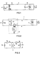
- Fig. 1 shows a circuit diagram of a general data transmission system using the parallel signal input method.
- the general transmission system comprises transmission wirings or lines 1 which can be power supply conductors or power wirings, a transmitting station 2 (where E s is a transmitting output voltage and Z s is an output impedance of the transmitting station 2), a receiving station 3 (where Z R is an input impedance of the receiving station 3), loads 4 and 5 (where Z LS and Z LR are impedances of loads 4 and 5, respectively).
- a receiving voltage E R can be expressed by the following equation.
- Effective signals for transmitting data are not applied on the transmitting wirings or lines 1 by using either the current I R or the voltage E R .
- Fig. 2 shows a circuit diagram of a data transmission system according to an embodiment of the present invention. Components similar to those in Fig. 1 are represented by the same reference numbers..
- a transformer 7 on the transmitting station 2 generates transmitting signals upon a transmission wiring a by using a magnetic coupling.
- An impedance element 8 (having an impedance Z A ) provides a current induced on the wiring a to the other transmission wiring b.
- the impedance element 8 exhibits a low impedance at the data transmission frequency, the impedance element 8 exhibiting a high impedance in response to the application of a power supply frequency while signals are transmitted by the power wirings.
- the impedance element 8 may be a capacitor or a series resonance circuit including a capacitor and a coil, so that the resonance frequency is made identical with the transmitting frequency.
- a switching means 9 is switched ON when signals are transmitted only from the transmitting station 2 so that the impedance element 8 does not at other times function as a load on another transmission system.
- Fig. 3 shows an equivalent circuit of Fig. 2.
- Fig. 3 there are connected a series impedance Z x , a signal detector impedance Zy, a mutual inductance M, the coils L 1 and L z having the numbers of turns L 1 and L Z .
- the impedances Z x and Zy can be written as follows:
- a receiving current I R as shown in Fig. 3 is expressed by the following equation (6).
- the signs ⁇ are determined by the direction in which the coil is wound. Because the impedance Z A is set equal nearly zero, the impedance Z x becomes equal nearly zero. If L 1 is selected to be ⁇ L 1 »Z s , the receiving current I R is expressed by the following equation (6').
- equations (7) and (8) are expressed as follows:
- Z y ⁇ 0 the equations (7) and (8) are expressed as follows:
- Signals can be applied to the wirings by the current or voltage in spite of the value of the impedance Z LR and the impedance Zy.
- a series circuit including the impedance 8 and the switching means 9 as shown Fig. 2 may be set opposite to the transformer 7.
- Fig. 4 shows a circuit diagram of a transmission system which comprises the above series circuits to the both neighbors of the transformer 7 according to another embodiment of the present invention.
- Operation modes of the data transmission system as shown Fig. 4 can set as shown in a table 1 when the switching means 9 and 9' are ON and OFF. Accordingly, signals can be transmitted in a desired direction in response to the connection of the switching means 9 and 9'.
- receiving is executed by both a current coupling used as a magnetic coupling of the coils and a voltage coupling connected to two transmitting wirings. If the transmission system comprises a receiving circuit having a simple structure such as the embodiment of the present invention, receiving can be executed easily.
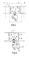
- Fig. 5 shows a circuit diagram of the data transmission system including a transmission/receiving circuit used as a core according to another embodiment of the present invention.
- a coil 10 induces a current for flowing on a wiring a by using the magnetic flux coupling because the coil 10 is combined with the core of the transformer 7. Further, the coil 10 induces a voltage by connecting itself to wirings a and b.
- a capacitor 11 forms a series resonance circuit with the coil 10, to induce only the signals corresponding to the transmitting frequency.
- An input impedance 12 is part of the receiving station 13. When the switching means 9 and 9' are ON, a voltage of the both ends of the impedance 12 in the receiving station 13 becomes nearly zero, so that no signals are received at the receiving station.
- the data transmission system includes two transmitting wirings, in which one of the transmission wirings is connected by magnetic coupling, an element is provided for serving as a low impedance at the data transmission frequency, the element being connected between the two wirings.
- an element is provided for serving as a low impedance at the data transmission frequency, the element being connected between the two wirings.
Description
- This invention relates to data transmission systems.
- More specifically, this invention relates to a data transmission system of the type having a communication channel comprising first and second conductors and a data transmitter operable to apply data signals on to said channel, the transmitter having means for inductively applying data signals to a first of said conductors, and means which exhibits a low impedance at the data signals frequency for providing, during transmission, a data path from said first conductor to the other conductor.
- A system of this type is known from FR-A-685115. In that known system the first and second conductors are part of an urban electricity supply system which includes at least one transformer, and the data path is provided across the terminals of the transformer in order to ensure that data signals are not passed on by the transformer to other parts of the electricity supply system and also to ensure that the transformer winding does not attenuate the data signals.
- The system of the present invention is characterised in that the data path includes switch means provided for selectively opening and closing said data path, whereby the data path can be closed during transmissions by said transmitter, and opened during other periods so as to prevent the low impedance means from acting as a load for other transmissions along the channel.
- Thus, when the switch means is closed, the transmitter is not prevented from performing accurate transmission of data signals even when a low impedance load is connected between the two conductors and, when the switch means is open, the low impedance of the data path does not act as a load for other possible transmissions on the channel.
- Preferably, the system also includes a further low impedance means and a further switch means for providing a further data path between said first and second conductors, the transmitter being coupled to said first conductor at a position between said data paths, whereby both switch means can be operated in accordance with the desired flow of data signals along the communication channel.
- Therefore, in this case, a choice can be made as to whether to transmit the data in one direction along the channel or, in the opposite direction.
- Other preferred features and advantages of the invention will be apparent from the following description given by way of example of a conventional system and of embodiments of the invention, reference being made to the accompanying drawings, in which:
- Fig. 1 shows a circuit diagram of a conventional data transmission system;
- Fig. 2 shows a circuit diagram of a data transmission system according to an embodiment of the present invention;
- Fig. 3 shows an equivalent circuit of a data transmission system of Fig. 2;
- Fig. 4 shows a circuit diagram of a data transmission system of another embodiment of the present invention; and
- Fig. 5 shows a circuit diagram of a data transmission system according to another embodiment of the present invention.
- Fig. 1 shows a circuit diagram of a general data transmission system using the parallel signal input method. The general transmission system comprises transmission wirings or
lines 1 which can be power supply conductors or power wirings, a transmitting station 2 (where Es is a transmitting output voltage and Zs is an output impedance of the transmitting station 2), a receiving station 3 (where ZR is an input impedance of the receiving station 3),loads 4 and 5 (where ZLS and ZLR are impedances ofloads - A receiving voltage ER can be expressed by the following equation.


- Further, if Z,.s»ZLR, the receiving voltage ER is given by the following equation in view of equations (1) and (2).

- Accordingly, signals can not be received on the receiving station by using the voltage ER when ZLR0. But, because a transmission current IS
 0, a receiving current IR is given as follows:

- But, when ZLS0, the receiving current IR and the transmission current IS and the receiving voltage E, are given as follows:


- Effective signals for transmitting data are not applied on the transmitting wirings or
lines 1 by using either the current IR or the voltage ER. - With this difficulty in mind, it is an object of the following embodiment to provide an improved data transmission system which is not prevented from performing accurate transmission even by a load connected between the two wirings or lines while the data are transmitted.
- Fig. 2 shows a circuit diagram of a data transmission system according to an embodiment of the present invention. Components similar to those in Fig. 1 are represented by the same reference numbers..
- A
transformer 7 on the transmittingstation 2 generates transmitting signals upon a transmission wiring a by using a magnetic coupling. An impedance element 8 (having an impedance ZA) provides a current induced on the wiring a to the other transmission wiring b. Theimpedance element 8 exhibits a low impedance at the data transmission frequency, theimpedance element 8 exhibiting a high impedance in response to the application of a power supply frequency while signals are transmitted by the power wirings. For example, theimpedance element 8 may be a capacitor or a series resonance circuit including a capacitor and a coil, so that the resonance frequency is made identical with the transmitting frequency. - A
switching means 9 is switched ON when signals are transmitted only from the transmittingstation 2 so that theimpedance element 8 does not at other times function as a load on another transmission system. - Fig. 3 shows an equivalent circuit of Fig. 2. In Fig. 3, there are connected a series impedance Zx, a signal detector impedance Zy, a mutual inductance M, the coils L1 and Lz having the numbers of turns L1 and LZ. Using the symbols in Fig. 2, the impedances Zx and Zy can be written as follows:
-

- A receiving current IR as shown in Fig. 3 is expressed by the following equation (6).


- If the
transformer 7 is high coupled, the mutual inductance M becomes.
- By simplifying the equation (6'), the result can be written as:


- Accordingly, when Zy→∞, equations (7) and (8) are expressed as follows:


- Signals can be applied to the wirings by the current or voltage in spite of the value of the impedance ZLR and the impedance Zy.
- When another transmission system is present, a series circuit including the
impedance 8 and the switching means 9 as shown Fig. 2 may be set opposite to thetransformer 7. Fig. 4 shows a circuit diagram of a transmission system which comprises the above series circuits to the both neighbors of thetransformer 7 according to another embodiment of the present invention. - Operation modes of the data transmission system as shown Fig. 4 can set as shown in a table 1 when the switching means 9 and 9' are ON and OFF. Accordingly, signals can be transmitted in a desired direction in response to the connection of the switching means 9 and 9'.

- In the present invention, receiving is executed by both a current coupling used as a magnetic coupling of the coils and a voltage coupling connected to two transmitting wirings. If the transmission system comprises a receiving circuit having a simple structure such as the embodiment of the present invention, receiving can be executed easily.
- Fig. 5 shows a circuit diagram of the data transmission system including a transmission/receiving circuit used as a core according to another embodiment of the present invention. As shown in Fig. 5, a
coil 10 induces a current for flowing on a wiring a by using the magnetic flux coupling because thecoil 10 is combined with the core of thetransformer 7. Further, thecoil 10 induces a voltage by connecting itself to wirings a and b. Acapacitor 11 forms a series resonance circuit with thecoil 10, to induce only the signals corresponding to the transmitting frequency. Aninput impedance 12 is part of thereceiving station 13. When the switching means 9 and 9' are ON, a voltage of the both ends of theimpedance 12 in thereceiving station 13 becomes nearly zero, so that no signals are received at the receiving station. - In the above description, the data transmission system includes two transmitting wirings, in which one of the transmission wirings is connected by magnetic coupling, an element is provided for serving as a low impedance at the data transmission frequency, the element being connected between the two wirings. In the case where low impedance loads are connected between both ends of two wirings, some signals as data can be transmitted by using either current or voltage.
Claims (6)
Applications Claiming Priority (2)
| Application Number | Priority Date | Filing Date | Title |
|---|---|---|---|
| JP57099914A JPS58215832A (en) | 1982-06-09 | 1982-06-09 | Data transmission system |
| JP99914/82 | 1982-06-09 |
Publications (2)
| Publication Number | Publication Date |
|---|---|
| EP0098066A1 EP0098066A1 (en) | 1984-01-11 |
| EP0098066B1 true EP0098066B1 (en) | 1987-09-30 |
Family
ID=14260042
Family Applications (1)
| Application Number | Title | Priority Date | Filing Date |
|---|---|---|---|
| EP83303349A Expired EP0098066B1 (en) | 1982-06-09 | 1983-06-09 | A data transmission system |
Country Status (5)
| Country | Link |
|---|---|
| US (1) | US4528677A (en) |
| EP (1) | EP0098066B1 (en) |
| JP (1) | JPS58215832A (en) |
| CA (1) | CA1213014A (en) |
| DE (1) | DE3373958D1 (en) |
Families Citing this family (9)
| Publication number | Priority date | Publication date | Assignee | Title |
|---|---|---|---|---|
| US4620187A (en) * | 1984-12-11 | 1986-10-28 | International Business Machines Corp. | Transformer coupled, solid state communications line switch |
| US4736452A (en) * | 1986-09-17 | 1988-04-05 | The Boeing Company | Core coupled transmitter/receiver loops for connectorless entertainment systems |
| US5084864A (en) * | 1990-05-14 | 1992-01-28 | The Boeing Company | Broadband, inductively coupled, duplex, rf transmission system |
| JPH04177923A (en) * | 1990-11-09 | 1992-06-25 | Sekiyu Kodan | Signal repeater |
| JPH05315999A (en) * | 1992-05-11 | 1993-11-26 | Fujitsu Ltd | Digital transmitting equipment |
| AU739897B2 (en) * | 1996-12-24 | 2001-10-25 | United Energy Ltd. | A termination circuit |
| AUPO440796A0 (en) * | 1996-12-24 | 1997-01-23 | United Energy Ltd. | A termination circuit |
| DE10062762A1 (en) | 2000-12-13 | 2002-08-22 | Siemens Ag | Arrangement and method for data transmission of digital transmission data |
| GB2469802B (en) * | 2009-04-28 | 2011-04-13 | Roke Manor Research | Data bus for low power tag |
Family Cites Families (8)
| Publication number | Priority date | Publication date | Assignee | Title |
|---|---|---|---|---|
| US1928610A (en) * | 1922-12-15 | 1933-10-03 | American Telephone & Telegraph | High frequency signaling system |
| FR685115A (en) * | 1928-11-26 | 1930-07-04 | Siemens Ag | Arrangement for the series superposition of control currents at foreign frequency on high current networks |
| US2499180A (en) * | 1946-06-25 | 1950-02-28 | Union Switch & Signal Co | Communication system |
| US2596013A (en) * | 1950-01-17 | 1952-05-06 | Westinghouse Air Brake Co | Transmitting and receiving circuits for inductive carrier communication systems |
| US3543262A (en) * | 1967-05-19 | 1970-11-24 | Westinghouse Air Brake Co | Signal distribution circuit having inductive attenuation means |
| US3740549A (en) * | 1969-12-24 | 1973-06-19 | Westinghouse Electric Corp | Remote signaling system for train control |
| ZA783933B (en) * | 1977-07-15 | 1979-07-25 | Coal Ind | Communication system |
| US4428078A (en) * | 1979-03-26 | 1984-01-24 | The Boeing Company | Wireless audio passenger entertainment system (WAPES) |
-
1982
- 1982-06-09 JP JP57099914A patent/JPS58215832A/en active Granted
-
1983
- 1983-06-06 US US06/501,252 patent/US4528677A/en not_active Expired - Lifetime
- 1983-06-08 CA CA000429944A patent/CA1213014A/en not_active Expired
- 1983-06-09 EP EP83303349A patent/EP0098066B1/en not_active Expired
- 1983-06-09 DE DE8383303349T patent/DE3373958D1/en not_active Expired
Non-Patent Citations (1)
| Title |
|---|
| Patent Abstracts of Japan,vol.3 No.22 (E-93) 24 February l979.page 76 E.93 * |
Also Published As
| Publication number | Publication date |
|---|---|
| DE3373958D1 (en) | 1987-11-05 |
| JPS58215832A (en) | 1983-12-15 |
| CA1213014A (en) | 1986-10-21 |
| US4528677A (en) | 1985-07-09 |
| JPS6240893B2 (en) | 1987-08-31 |
| EP0098066A1 (en) | 1984-01-11 |
Similar Documents
| Publication | Publication Date | Title |
|---|---|---|
| US6414578B1 (en) | Method and apparatus for transmitting a signal through a power magnetic structure | |
| US5497142A (en) | Directional separator-coupler circuit for medium-frequency carrier currents on a low-voltage electrical line | |
| US5210519A (en) | Digital data transmission | |
| US3731234A (en) | Combined voice frequency transmission and dc signaling circuit | |
| EP0098066B1 (en) | A data transmission system | |
| EP0091824A2 (en) | Receiving circuit for a data transmission system | |
| EP0124260A2 (en) | Power supply line carrier communication systems | |
| CA1165461A (en) | Printed circuit transformers | |
| US4951312A (en) | Balanced transmission device | |
| EP1237295B1 (en) | Balanced transmission termination device | |
| EP0499311A1 (en) | Transformer | |
| US5426697A (en) | Duplex communication coupler system | |
| FI800918A (en) | ANALYZING MEDIA FOER TVAOLEDAR-FYRLEDAR-OEVERGAONG I PCM-TIDSMULTIPLEXSYSTEM | |
| JP2001520849A (en) | Transmitting / receiving station having impedance matching receiving means for transponder response signal | |
| WO2002050851A1 (en) | Transformer providing low output voltage | |
| US4620187A (en) | Transformer coupled, solid state communications line switch | |
| ATE47767T1 (en) | HF BROADBAND TRANSMITTER CIRCUIT. | |
| RU2143784C1 (en) | Wide-band connection device with directed features | |
| SU1653166A1 (en) | Device for signal transmission via a three-phase power distribution line | |
| JPH0336340B2 (en) | ||
| ATE103432T1 (en) | HIGH FREQUENCY DIRECTIONAL COUPLER TAP. | |
| JPS6224606A (en) | Branch transformer | |
| JPS6316725A (en) | Low voltage distribution line carrier metallic circuit system | |
| JPS61125214A (en) | Branching circuit | |
| JPH02243040A (en) | Isolation method for differential signal transmission line |
Legal Events
| Date | Code | Title | Description |
|---|---|---|---|
| PUAI | Public reference made under article 153(3) epc to a published international application that has entered the european phase |
Free format text: ORIGINAL CODE: 0009012 |
|
| AK | Designated contracting states |
Designated state(s): DE FR GB IT |
|
| 17P | Request for examination filed |
Effective date: 19840322 |
|
| ITF | It: translation for a ep patent filed |
Owner name: DR. ING. A. RACHELI & C. |
|
| GRAA | (expected) grant |
Free format text: ORIGINAL CODE: 0009210 |
|
| AK | Designated contracting states |
Kind code of ref document: B1 Designated state(s): DE FR GB IT |
|
| REF | Corresponds to: |
Ref document number: 3373958 Country of ref document: DE Date of ref document: 19871105 |
|
| ET | Fr: translation filed | ||
| PLBE | No opposition filed within time limit |
Free format text: ORIGINAL CODE: 0009261 |
|
| STAA | Information on the status of an ep patent application or granted ep patent |
Free format text: STATUS: NO OPPOSITION FILED WITHIN TIME LIMIT |
|
| 26N | No opposition filed | ||
| ITTA | It: last paid annual fee | ||
| PGFP | Annual fee paid to national office [announced via postgrant information from national office to epo] |
Ref country code: GB Payment date: 19970602 Year of fee payment: 15 |
|
| PGFP | Annual fee paid to national office [announced via postgrant information from national office to epo] |
Ref country code: FR Payment date: 19970610 Year of fee payment: 15 |
|
| PGFP | Annual fee paid to national office [announced via postgrant information from national office to epo] |
Ref country code: DE Payment date: 19970613 Year of fee payment: 15 |
|
| PG25 | Lapsed in a contracting state [announced via postgrant information from national office to epo] |
Ref country code: GB Free format text: LAPSE BECAUSE OF NON-PAYMENT OF DUE FEES Effective date: 19980609 |
|
| GBPC | Gb: european patent ceased through non-payment of renewal fee |
Effective date: 19980609 |
|
| PG25 | Lapsed in a contracting state [announced via postgrant information from national office to epo] |
Ref country code: FR Free format text: LAPSE BECAUSE OF NON-PAYMENT OF DUE FEES Effective date: 19990226 |
|
| PG25 | Lapsed in a contracting state [announced via postgrant information from national office to epo] |
Ref country code: DE Free format text: LAPSE BECAUSE OF NON-PAYMENT OF DUE FEES Effective date: 19990401 |
|
| REG | Reference to a national code |
Ref country code: FR Ref legal event code: ST |