EP0097745B1 - Maschine zum Schneiden konischer Gewinde - Google Patents
Maschine zum Schneiden konischer Gewinde Download PDFInfo
- Publication number
- EP0097745B1 EP0097745B1 EP82304119A EP82304119A EP0097745B1 EP 0097745 B1 EP0097745 B1 EP 0097745B1 EP 82304119 A EP82304119 A EP 82304119A EP 82304119 A EP82304119 A EP 82304119A EP 0097745 B1 EP0097745 B1 EP 0097745B1
- Authority
- EP
- European Patent Office
- Prior art keywords
- recess
- block
- chaser
- tapered thread
- head
- Prior art date
- Legal status (The legal status is an assumption and is not a legal conclusion. Google has not performed a legal analysis and makes no representation as to the accuracy of the status listed.)
- Expired
Links
- 238000005520 cutting process Methods 0.000 title abstract description 11
- 230000002093 peripheral effect Effects 0.000 claims description 2
- 230000013011 mating Effects 0.000 claims 1
- 230000036346 tooth eruption Effects 0.000 claims 1
- 238000003754 machining Methods 0.000 abstract description 23
- 238000010276 construction Methods 0.000 description 6
- 230000015572 biosynthetic process Effects 0.000 description 5
- 229910001315 Tool steel Inorganic materials 0.000 description 3
- 230000005540 biological transmission Effects 0.000 description 3
- 238000005266 casting Methods 0.000 description 3
- 244000145845 chattering Species 0.000 description 3
- 238000003780 insertion Methods 0.000 description 3
- 230000037431 insertion Effects 0.000 description 3
- 239000000463 material Substances 0.000 description 3
- 229910000831 Steel Inorganic materials 0.000 description 2
- 230000008878 coupling Effects 0.000 description 2
- 238000010168 coupling process Methods 0.000 description 2
- 238000005859 coupling reaction Methods 0.000 description 2
- 230000003014 reinforcing effect Effects 0.000 description 2
- 239000010959 steel Substances 0.000 description 2
- 230000004075 alteration Effects 0.000 description 1
- 239000004411 aluminium Substances 0.000 description 1
- 229910052782 aluminium Inorganic materials 0.000 description 1
- XAGFODPZIPBFFR-UHFFFAOYSA-N aluminium Chemical compound [Al] XAGFODPZIPBFFR-UHFFFAOYSA-N 0.000 description 1
- 239000010730 cutting oil Substances 0.000 description 1
- 230000000977 initiatory effect Effects 0.000 description 1
- 230000003993 interaction Effects 0.000 description 1
- 238000004519 manufacturing process Methods 0.000 description 1
- 229910052751 metal Inorganic materials 0.000 description 1
- 239000002184 metal Substances 0.000 description 1
- 238000012986 modification Methods 0.000 description 1
- 230000004048 modification Effects 0.000 description 1
Images

Classifications
-
- B—PERFORMING OPERATIONS; TRANSPORTING
- B23—MACHINE TOOLS; METAL-WORKING NOT OTHERWISE PROVIDED FOR
- B23G—THREAD CUTTING; WORKING OF SCREWS, BOLT HEADS, OR NUTS, IN CONJUNCTION THEREWITH
- B23G5/00—Thread-cutting tools; Die-heads
- B23G5/08—Thread-cutting tools; Die-heads with means for adjustment
- B23G5/10—Die-heads
-
- Y—GENERAL TAGGING OF NEW TECHNOLOGICAL DEVELOPMENTS; GENERAL TAGGING OF CROSS-SECTIONAL TECHNOLOGIES SPANNING OVER SEVERAL SECTIONS OF THE IPC; TECHNICAL SUBJECTS COVERED BY FORMER USPC CROSS-REFERENCE ART COLLECTIONS [XRACs] AND DIGESTS
- Y10—TECHNICAL SUBJECTS COVERED BY FORMER USPC
- Y10T—TECHNICAL SUBJECTS COVERED BY FORMER US CLASSIFICATION
- Y10T408/00—Cutting by use of rotating axially moving tool
- Y10T408/83—Tool-support with means to move Tool relative to tool-support
- Y10T408/85—Tool-support with means to move Tool relative to tool-support to move radially
- Y10T408/858—Moving means including wedge, screw or cam
- Y10T408/8593—Wedge moving perpendicular to tool-axis
-
- Y—GENERAL TAGGING OF NEW TECHNOLOGICAL DEVELOPMENTS; GENERAL TAGGING OF CROSS-SECTIONAL TECHNOLOGIES SPANNING OVER SEVERAL SECTIONS OF THE IPC; TECHNICAL SUBJECTS COVERED BY FORMER USPC CROSS-REFERENCE ART COLLECTIONS [XRACs] AND DIGESTS
- Y10—TECHNICAL SUBJECTS COVERED BY FORMER USPC
- Y10T—TECHNICAL SUBJECTS COVERED BY FORMER US CLASSIFICATION
- Y10T408/00—Cutting by use of rotating axially moving tool
- Y10T408/89—Tool or Tool with support
- Y10T408/904—Tool or Tool with support with pitch-stabilizing ridge
- Y10T408/9046—Tool or Tool with support with pitch-stabilizing ridge including tapered section
- Y10T408/90473—Tool or Tool with support with pitch-stabilizing ridge including tapered section including work-embracing cutting edges
Definitions
- This invention relates to a tapered thread cutting machine and more particularly to certain improvements in relatively small and portable thread cutting machines for forming an external tapered thread on the ends of bar stock and the like such as concrete reinforcing bar.
- a rotary machining head which includes a recess in its face.
- tooling holders are mounted which in turn support the chasers which may be opened and closed for successive passes for the formation of the thread.
- a linear cam through a thrust block causes movement of one of the chaser holders which in turn because of their cooperating configuration within the recess causes movement of all.
- the surfaces thereof must be machined and finished to a substantial degree of precision to avoid binding or chattering during the movement of the parts and to prevent excessive wear.
- the rotary maching head is normally formed from a single large casting with the recess being formed therein by an end mill operation. After the recess is formed the back wear plate is normally press fit into the recess thus formed. Because of the end mill operation which necessarily entails tooling or spindle deflection, and the press fit operation, the precision of formation of the inside surfaces of the recess and the wear plate, when assembled within the recess, cannot be ensured. Furthermore, the balance of the rotary machining head which is connected to the transmission is unnecessarily massive and heavy when utilizing a one-piece casting.
- cam thrust block which is fastened to one of the holders and which is held against the linear cam by a spring which seats against the back of the thrust block.
- This type of design may tend create an eccentric loading which is transferred from the thrust block to the associated tool holder further creating binding in the movement of the tool holders which causes problems in both the opening and closing, and particularly closing of such holders.
- prior art tool holders and the chasers supported thereby are unnecessarily complex with the chasers fitting in recesses or openings in the tool holders and requiring disassembly of the tool holders from the recess to replace the chasers.
- the special chasers required to fit the tool holders are of complex shapes requiring a multiplicity of machining and grinding operations making the wear replacement chasers unduly expensive to manufacture in addition to the problem of disassembly for replacement.
- a tapered thread cutter for bar stock and the like comprising a rotary head block including a polygonally shaped recess supporting and guiding chaser holders on respective interior facets thereof for opening and closing movement, characterised in that the head block is formed of at least two parts, one part having interior walls forming the recess which is open at both axial ends of said first part, said interior walls being in planes parallel to the rotary axis of the head block and in precise relationship to each other.
- a rotary head block which is formed of at least two parts.
- One part includes the recess which is formed as a through-recess in that part enabling the interior walls thereof to be formed to a considerable degree of precision.
- a removable wear plate is preferably secured to said one part so as to at least partially close one end of the recess.
- a third part of the head block may be provided which comprises a balance head extension connected to the transmission and which may be of lighter weight material. The three parts are assembled enabling the formation of the recess and the interior wear plate in a precise relationship heretofore unobtainable. In this manner, the recess does not have to be formed by an end mill subject to tooling or spindle deflections nor does the wear plate require to be press fit into the recess.
- the opening and closing of the tool holders may be obtained through utilization of a cam thrust block which is mounted on one of the tool holders without a fastener and in a slot with a tight fit, but which has some play for insertion and removal.
- the cam thrust block is in turn mounted on a guide pin or rod which goes completely through the thrust block and through a spring.
- the spring is preferably captured by a head on the rod and a removable plug in turn captures the head. This construction has been found to minimize binding or chattering in the adjustment for movement of the tool holders.
- the chaser may be formed in a much more economical manner simply by cutting essentially rectangular blocks from elongated chaser stock and then surface grinding or relieving the cutting edges.
- the chaser may be held in the tool holder in a relatively simple angled V-shaped slot by an adjustable clamp.
- the adjustable clamp exerts a component of force to hold the chaser against the walls or the back of the slot and against the stop pin.
- the construction of each tool holder is essentially the same. However, the stop of each successive tool holder may be axially offset from the stop of the next holder by the reciprocal of the number of chasers employed times the pitch of the thread being cut. In any case the chasers may much more economically be formed and may be removed and replaced without disassembly of the tool holder from the recess.
- a wear plate may be provided which is formed separately and does not require to be pressed through the recess for assembly.
- one of the holders within the recess includes a projecting cam thrust block through which a guide rod extends parallel to the movement of the holder with spring means surrounding the guide rod urging the thrust block against a control cam.
- the thrust block is mounted in a recess in the holder from which it projects but is otherwise unconnected to the holder.
- the chaser holders may include on their interior an angularly disposed recess with a stop at one end of the recess and a clamp at the other end operative hold a chaser in the recess.
- the recess is preferably a V-shape groove on the interior of the holder and the clamp includes a component of force seating the chaser into the groove and against the stop.
- the chasers can readily be manufactured in the form of rectangular blocks and secured in and removed from the holders without requiring disassembly or removal of the holders from the head recess.
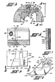
- a rotary machining head block 10 which is normally formed of a single steel casting.
- the block is mounted in the machine with its drive for axial reciprocation in the direction of the arrow 11 with the end 12 of the block being connected to the drive transmission while the opposite end 13 is provided with a recess 14.
- the recess is shown in the form of a square and closed at its inner end by a wear plate 15 which is normally pressed through the opened end of the recess.
- Fitted within the recess 14 are four relatively complex tooling holders seen at 18, 19, 20 and 21, such that movement of one tool holder when within the recess moves all tool holders for opening and closing movement.
- One of the tool holders shown at 18 is provided with an exterior recess 23 which seats a cam thrust block 24 held thereto by fastener 25.
- the cam thrust block 24 projects upwardly in the assembled condition of the tool holders through a substantially radial slot 27 in the head 10 which intersects with a linear external axial slot 28.
- a control key or cam 30 mounted within the axial slot 28 is a control key or cam 30 which includes a linear cam surface 31 on the underside thereof which abuts against the upper edge 32 of the cam thrust block 24.
- springs 34 and 35 trapped in a hole 36 between a threaded plug 37 and a seat 38 in the face of the cam thrust block opposite the cam engaging surface 31.
- Movement of the control cam 30 is obtained by axially spaced rollers 40 and 41 held in place by shoulder bolts 42 and 43, respectively.
- the rollers 40 and 41 are positioned on opposite sides of an axially adjustable control ring 44 shown fragmentarily in Figure 1.
- Adjustment of the ring 44 is employed initially to contact the roller 40 to move the cam or key to a starting position which closes the holders a predetermined amount.
- a control setting is employed for this purpose. This setting establishes the amount of metal to be removed for the pass.
- roller 41 engages the ring 44 initiating the uniform opening of the holders by a linear angled portion of the cam (the same as the taper being cut). In this manner, each chaser has a uniform depth of cut for each pass. At the end of the pass the cam is provided with a portion which opens the holders permitting the cam to be reset for the next pass.
- the number of passes employed may of course depend upon the diameter of the bar being threaded.
- each chaser holder 18 to 21 is provided with a major slot 46 in which the chaser 47 is inserted in the direction of the double-ended arrow 48.
- One edge of the slot is 46 closed by a chaser clamping plate 49 secured by fasteners 50 to the chaser holder.
- the lateral edges of the clamping plate 49 are provided with flanges fitting within the flange recesses illustrated.
- the extent to which the chaser 47 is inserted in the holder may be controlled by a stop pin which engages a finished flat 53 or by a threaded stud engaging a shoulder on the chaser.
- chaser 47 In normal practice, to remove a chaser 47, the tool holders 18 to 21 must normally be removed from the recess 14. The chaser clamping plates 49 are then loosened and the chasers are then pulled from the holders in the direction of the arrow 48. Also, care must be taken to replace the chasers and holders in a precise order. It can be seen that the chasers cannot be pulled from the assembly in the manner indicated when the holders are in the recess because of the close fit and relationship therebetween.
- the rotary machining head shown generally at 60 is substantially formed of three separate parts which may be termed a machining head 61, a wear plate 62 and a machining head extension 63.
- the machining head 61 is provided with a square through-recess 64. Because the recess 64 is a through-recess, it need not be formed by an end mill subject to spindle or tool deflection. In this manner, the planar interior walls 65, 66, etc. may be formed precisely at right angles to each other and precisely in planes parallel to the rotary axis of the rotary machining head 60. Since the tool holders are designed to slide within the precise interior walls 65, 66 of a true square box, the formation of the recess in this manner itself minimizes binding, chattering, or excess wear which might otherwise occur.
- the wear plate 62 which forms the end wall of the recess 64 may be formed with flat opposite faces and may be secured or clamped between the head 61 and head extension 63 against a flat surface 68 forming the rear of the machining head 61 to ensure that the finished surface 69 is normal to the axis of the assembly. Press fitting such a wear plate into the open end of a recess in a one-piece machining head as in the prior art arrangement cannot assure the normality and planarity of the wear plate as with the present invention.
- the wear plate 62 forms a wear surface for the chaser holders.
- the machining head extension 63 which forms the larger volume of the rotary machining head assembly may be formed from a lighter weight material, such as aluminium, thus significantly reducing the total mass of the rotary assembly while still obtaining the precision of the bearing and wear surfaces for the chaser holders.
- the plate 62 and the extension 63 are formed with aligned centre holes for the stock and cutting oil.
- the machining head extension 63 on its forward end has a peripheral skirt 70 which encloses the periphery of the wear plate 62 and which seats against a shoulder 71 on the rear of the machining head 61.
- the parts of the machining head may be assembled with the assistance of one or more dowl pins 72.
- Each of the three major components of the assembly include aligned slots seen at 74, 75 and 76 to receive a control key or cam 77.
- the chaser tool holder 80 adjacent the cam 77 is provided with an exterior axial slot 81 in which an extension 82 of a cam thrust block 83 is fitted.
- the cam thrust block 83 is provided with a transaxial through-hole 84 and optionally may include a top removable wear insert 85 designed to bear against the linear interior cam surface 86 of the control key or cam 77.
- the intersecting slot 88 accommodates the cam thrust block 83 for movement transversely of the slot 74 and of course the control cam surface 86.
- the thrust block 83 is mounted on a hardened support pin or guide rod 90 which includes a head 91.
- the rod 90 fits closelythrough hole 84 in the cam thrust block 83.
- a spring 93 fits around the pin 90 between the thrust block 83 and the head 91 and the entire assembly is captured in a hole 94 by a threaded plug 95.
- the square recess 64 is designed to accommodate four interacting tool holders 80, 98 with only the two opposite tool holders 80, 98 being shown in Figure 2.
- the opposite tool holder 98 is shown with its chaser 99 removed.
- the chaser 100 of the tool holder 80 is shown assembled. Since the tool holders 80, 98 are substantially the same, only the tool holder 98 seen in detail in Figures 5 and 6 will be described.
- the tool holder 98 is essentially in the form of a triangular block with the apex relieved as well as one corner along the base or interior face removed.
- the tool holder 98 includes an inner surface 102 forming the base of the triangular block and two outer faces 103 and 104 which are at right angles to each other.
- the face 103 of the tool holder 98 forms a guide face guiding the tool holder along the wall 66 of the recess 64.
- the apex of the triangular block is relieved between the surfaces 103 and 104 as seen at 105 to provide clearance for the rounded corners of the recess 64.
- the corner at one end of the base or inner surface 102 may be slightly relieved as seen at 106 while the opposite end of the block at the base is provided with a guide surface 107 which is at right angles to the inner face or base 102.
- the guide surface 107 rides against the inner face 102 of the adjacent tool holder.
- the block is provided with an inner end face 109 and an outer end face 110. Both end faces are at right angles to the other major faces.
- the inner end face 109 rides against the wear plate 62 and thus it is important that the surface 69 of the wear plate 62 be perfectly flat and that the inner walls 65, 66 of the recess 64 also be perfectly flat and at right angles not only to each other but also to the wear plate 62.
- the outer end face 110 rides against a cover plate (not shown) secured to- the face or front of the machining head 61.
- each tool holder block is provided with a V-shaped groove seen generally at 114.
- the walls 115 and 116 of the V-shaped groove 114 may be at right angles to each other but the apex of the groove 114 or inner corner 117 thereof extends at an angle to the axis of the machine equal to the angle of taper of the thread to be generated on the workpiece.
- the wall 116 of the groove 114 extends at a slight angle downwardly while the wall 115 extends at a somewhat more severe angle outwardly. It is this slot 114 in which the chaser 99 is positioned and held.
- Chip clearance reliefs may be provided adjacent the slot 114 as indicated 120 and 121 with the latter clearance even being further relieved by a clearance 122.
- the associated chaser 99 is in the form of a substantially rectangular block and is clamped in the slot 114 by a clamp screw 124 passing through a dished or spring washer 125 and into a tapped blind bore 126 in the face 110 of the holder.
- face 110 is circularly relieved as indicated at 127 so that when the clamp screw 124 is seated in clamping arrangement with the chaser its head will clear the end face 110.
- the circular relief 127 intersects one end of the V-shaped slot 114 so that the dished washer 125 and head bear against an end of the chaser 99.
- the clamp screw 124 clamps the chaser 99 against a stop or locating pin 130 which is positioned in a blind bore 131 in the face 116 of the slot 114.
- axis 133 of the clamp screw 124 and its associated tapped bore 126 is normal to the end faces 109 and 110 of the tool holder while the surfaces 115 and 116 are not.
- the clamping force on the end of the chaser 99 exerts a component of force urging the chaser against both surfaces 115 and 116 in addition to clamping the chaser 99 against the stop pin 130.
- the axis of the blind bore 131 is parallel to the end faces 109 and 110.
- the chasers 99 may readily be formed from tool steel bar stock shown generally at 135 which is rectangular in section. On the top surface there may be milled the leading edge chamfers seen at 136 and the thread form cutters 137. After the bar stock 135 is properly milled it may be cut along the lines indicated at 138 to form the chaser blanks. The cutting edges may then be ground to form the necessary reliefs while the opposite edge is maintained as a right angle corner properly to seat in the slot 114 of the respective tool holder.
- the chaser bar stock 135 is also subsequently milled or finished to provide the required leading edge chamfers the chaser for each tool holder may be formed from the same bar stock with the only difference in the holder being the spacing of the locating pin 130. In this manner, the locating pin 130 of successive tool holders would be spaced the reciprocal of the number of tool holders times the pitch. If the locating pins for each tool holder are the same, then the chaser bar stock for the respective tool holders may be formed in essentially the same manner, but with leading edge chamfers and thread cutting sections positioned on different bar stock. In either event, the chasers may be formed of relatively simply rectangular bar stock and cut into substantially rectangular blocks for subsequent finishing for insertion in the required tool holders.
- the multi-piece rotary machining head avoids prior art problems finishing the interior surfaces of the recess against which the tool holders must move. The same is true of the interior wear plate. Moreover, in association therewith, the mounting of the cam thrust block on the associated tool holder without fasteners in a slot with a tight fit, but which has some play for insertion and removal, in combination with the mounting of such block on a rod which goes through the block, prevents cocking of the cam thrust block and if any does occur, it is then absorbed by the non-fastened connection between the block and holder.
- the multi-part construction of the rotary machining head enables the surfaces against which the chaser tooling holders ride to be much more precisely formed, the balance of the rotary machining head being of a lighter weight material reducing the energy required both to drive the unit and to form it.
- chasers and tool holders of the present invention are of a much more simplified construction.
- the chasers may be formed economically from tool steel bar stock and may either be formed such that the tool holders and the associated clamping screws and stops are identical or such that the tool steel stock be slightly modified and the position of the stop pin against which the chaser is clamped may be modified for each tool holder by the reciprocal of the number of tool holders times the pitch.
- the construction and formation of the chasers and of the associated tool holders is greatly simplified permitting chaser removal and replacement without removal and disassembly of the tool holders from the recess of the head.
Landscapes
- Engineering & Computer Science (AREA)
- Mechanical Engineering (AREA)
- Cutting Tools, Boring Holders, And Turrets (AREA)
- Sewing Machines And Sewing (AREA)
- Snaps, Bayonet Connections, Set Pins, And Snap Rings (AREA)
Claims (10)
Priority Applications (1)
| Application Number | Priority Date | Filing Date | Title |
|---|---|---|---|
| AT82304119T ATE25826T1 (de) | 1982-06-25 | 1982-08-04 | Maschine zum schneiden konischer gewinde. |
Applications Claiming Priority (2)
| Application Number | Priority Date | Filing Date | Title |
|---|---|---|---|
| US391681 | 1982-06-25 | ||
| US06/391,681 US4526496A (en) | 1982-06-25 | 1982-06-25 | Tapered thread cutting machine |
Publications (3)
| Publication Number | Publication Date |
|---|---|
| EP0097745A2 EP0097745A2 (de) | 1984-01-11 |
| EP0097745A3 EP0097745A3 (en) | 1984-05-09 |
| EP0097745B1 true EP0097745B1 (de) | 1987-03-11 |
Family
ID=23547540
Family Applications (1)
| Application Number | Title | Priority Date | Filing Date |
|---|---|---|---|
| EP82304119A Expired EP0097745B1 (de) | 1982-06-25 | 1982-08-04 | Maschine zum Schneiden konischer Gewinde |
Country Status (4)
| Country | Link |
|---|---|
| US (1) | US4526496A (de) |
| EP (1) | EP0097745B1 (de) |
| AT (1) | ATE25826T1 (de) |
| DE (1) | DE3275635D1 (de) |
Families Citing this family (2)
| Publication number | Priority date | Publication date | Assignee | Title |
|---|---|---|---|---|
| US5158404A (en) * | 1989-04-07 | 1992-10-27 | Erico International Corporation | Taper thread cutting machine and method |
| KR101637681B1 (ko) * | 2014-09-22 | 2016-07-07 | 현대자동차주식회사 | 보링 장치 |
Family Cites Families (18)
| Publication number | Priority date | Publication date | Assignee | Title |
|---|---|---|---|---|
| BE474012A (de) * | ||||
| FR474012A (fr) * | 1913-10-27 | 1915-02-04 | Societe Francaise De Joints Et De Caoutchouc | Cuir artificiel |
| US1492426A (en) * | 1920-02-21 | 1924-04-29 | Landis Machine Co | Chaser holder |
| CH116188A (de) * | 1925-10-29 | 1926-12-01 | Reishauer Werkzeuge Ag | Gasgewindeschneid- und Abstechmaschine. |
| DE484297C (de) * | 1926-03-16 | 1929-10-16 | Landis Machine Co | Mehrteiliger Gewindeschneidkopf mit selbsttaetig sich oeffnenden Schneidbacken |
| US1937418A (en) * | 1932-05-19 | 1933-11-28 | Eastern Machine Screw Corp | Die head |
| US2093506A (en) * | 1936-07-30 | 1937-09-21 | Cons Machine Tool Corp | Thread forming chaser and supporting means therefor |
| US2242954A (en) * | 1939-12-29 | 1941-05-20 | Ridge Tool Co | Diestock |
| CH289443A (de) * | 1950-11-23 | 1953-03-15 | Newington Bridges George | Gewindeschneidwerkzeug. |
| GB800019A (en) * | 1953-10-06 | 1958-08-20 | Christian Foell | Rotating thread cutting head for the cutting of conical and cylindrical screws |
| US2848726A (en) * | 1954-12-31 | 1958-08-26 | Landis Machine Co | Taper thread cutting die head with pivoted lever means to control taper |
| US2864102A (en) * | 1957-03-29 | 1958-12-16 | Electrical Fittings Corp | Die head providing quick change of chasers |
| US3107374A (en) * | 1959-12-11 | 1963-10-22 | Toledo Beaver Tools Inc | Clamping means for radially extending chasers |
| US3580690A (en) * | 1969-06-09 | 1971-05-25 | Michael Cerrito | Insert chaser die head |
| US3696454A (en) * | 1970-09-10 | 1972-10-10 | Teledyne Inc | Thread cutting die head |
| CH524420A (de) * | 1971-06-14 | 1972-06-30 | Fischer Ag Georg | Gewindeschneidkopf mit ausrückbaren Gewindeschneidbacken |
| GB2011298B (en) * | 1977-12-27 | 1982-05-12 | Foell Remswerk | Portable thread cutting machine for cutting external threads |
| DE2831718C2 (de) * | 1978-07-19 | 1987-05-07 | Rems-Werk Christian Föll und Söhne GmbH & Co, 7050 Waiblingen | Gewindeschneidbacke für Außengewindeschneidmaschinen |
-
1982
- 1982-06-25 US US06/391,681 patent/US4526496A/en not_active Expired - Fee Related
- 1982-08-04 AT AT82304119T patent/ATE25826T1/de not_active IP Right Cessation
- 1982-08-04 DE DE8282304119T patent/DE3275635D1/de not_active Expired
- 1982-08-04 EP EP82304119A patent/EP0097745B1/de not_active Expired
Also Published As
| Publication number | Publication date |
|---|---|
| ATE25826T1 (de) | 1987-03-15 |
| EP0097745A3 (en) | 1984-05-09 |
| DE3275635D1 (en) | 1987-04-16 |
| EP0097745A2 (de) | 1984-01-11 |
| US4526496A (en) | 1985-07-02 |
Similar Documents
| Publication | Publication Date | Title |
|---|---|---|
| US4631994A (en) | Adjustable holder for a cutting tool | |
| DE19725219C2 (de) | Fräswerkzeug mit axialer Einstellung des Plattensitzes | |
| DE68918254T2 (de) | Einstellbare Bohrstangeneinsatzpatrone. | |
| US3831237A (en) | Mounting apparatus for indexable cutting inserts | |
| EP0182290A2 (de) | Messerkopf | |
| DE10326662A1 (de) | Schneideinsatz zum Drehen und Fräsen | |
| HK110596A (en) | Tool with adjustable interchangeable cartridge | |
| RU2211750C2 (ru) | Режущий инструмент для высокоскоростной обработки | |
| EP0792709A2 (de) | Verfahren zum Herstellen von bogenförmigen Nuten und Werkzeug dazu | |
| US4784536A (en) | Drilling head | |
| DE102015115310A1 (de) | Wirbelwerkzeug | |
| KR20150054679A (ko) | 기어 호빙 공구, 기어 호빙 공구용 인서트 홀더, 칩 제거 유닛, 및 인서트 키트 | |
| EP2764933A1 (de) | Werkzeugsystem mit auswechselbaren Werkzeugeinsätzen für Stanzmaschinen | |
| US4580929A (en) | Machine tool with interchangeable insert-holding cartridges | |
| US3812547A (en) | Toolholder with interchangeable inserts for a tangent chaser | |
| EP0097745B1 (de) | Maschine zum Schneiden konischer Gewinde | |
| EP1995007A1 (de) | Plattensitz mit Einlegestücken | |
| US3868120A (en) | Chuck | |
| EP0123878B1 (de) | Bohrwerkzeug | |
| US4137000A (en) | Cutting tool | |
| CN112475804B (zh) | 一种超长狭窄t型槽加工方法 | |
| US3425305A (en) | Tool post and tool holder | |
| EP3606693A1 (de) | Bohrwerkzeug mit wechselschneidplatte | |
| DE3607528C1 (en) | Milling cutter head | |
| EP1718430A2 (de) | Werkzeug zur spanenden bearbeitung von präzisionsbohrungen |
Legal Events
| Date | Code | Title | Description |
|---|---|---|---|
| PUAI | Public reference made under article 153(3) epc to a published international application that has entered the european phase |
Free format text: ORIGINAL CODE: 0009012 |
|
| AK | Designated contracting states |
Designated state(s): AT BE CH DE FR GB IT LI LU NL SE |
|
| PUAL | Search report despatched |
Free format text: ORIGINAL CODE: 0009013 |
|
| AK | Designated contracting states |
Designated state(s): AT BE CH DE FR GB IT LI LU NL SE |
|
| 17P | Request for examination filed |
Effective date: 19841027 |
|
| GRAA | (expected) grant |
Free format text: ORIGINAL CODE: 0009210 |
|
| AK | Designated contracting states |
Kind code of ref document: B1 Designated state(s): AT BE CH DE FR GB IT LI LU NL SE |
|
| REF | Corresponds to: |
Ref document number: 25826 Country of ref document: AT Date of ref document: 19870315 Kind code of ref document: T |
|
| ITF | It: translation for a ep patent filed | ||
| REF | Corresponds to: |
Ref document number: 3275635 Country of ref document: DE Date of ref document: 19870416 |
|
| ET | Fr: translation filed | ||
| PG25 | Lapsed in a contracting state [announced via postgrant information from national office to epo] |
Ref country code: LU Free format text: LAPSE BECAUSE OF NON-PAYMENT OF DUE FEES Effective date: 19870831 |
|
| PLBE | No opposition filed within time limit |
Free format text: ORIGINAL CODE: 0009261 |
|
| STAA | Information on the status of an ep patent application or granted ep patent |
Free format text: STATUS: NO OPPOSITION FILED WITHIN TIME LIMIT |
|
| 26N | No opposition filed | ||
| PGFP | Annual fee paid to national office [announced via postgrant information from national office to epo] |
Ref country code: FR Payment date: 19900806 Year of fee payment: 9 |
|
| PGFP | Annual fee paid to national office [announced via postgrant information from national office to epo] |
Ref country code: AT Payment date: 19900808 Year of fee payment: 9 |
|
| PGFP | Annual fee paid to national office [announced via postgrant information from national office to epo] |
Ref country code: GB Payment date: 19900810 Year of fee payment: 9 |
|
| PGFP | Annual fee paid to national office [announced via postgrant information from national office to epo] |
Ref country code: BE Payment date: 19900814 Year of fee payment: 9 |
|
| PGFP | Annual fee paid to national office [announced via postgrant information from national office to epo] |
Ref country code: CH Payment date: 19900815 Year of fee payment: 9 |
|
| PGFP | Annual fee paid to national office [announced via postgrant information from national office to epo] |
Ref country code: SE Payment date: 19900816 Year of fee payment: 9 |
|
| PGFP | Annual fee paid to national office [announced via postgrant information from national office to epo] |
Ref country code: LU Payment date: 19900828 Year of fee payment: 9 |
|
| PGFP | Annual fee paid to national office [announced via postgrant information from national office to epo] |
Ref country code: DE Payment date: 19900829 Year of fee payment: 9 |
|
| ITTA | It: last paid annual fee | ||
| PGFP | Annual fee paid to national office [announced via postgrant information from national office to epo] |
Ref country code: NL Payment date: 19900831 Year of fee payment: 9 |
|
| PG25 | Lapsed in a contracting state [announced via postgrant information from national office to epo] |
Ref country code: GB Effective date: 19910804 Ref country code: AT Effective date: 19910804 |
|
| PG25 | Lapsed in a contracting state [announced via postgrant information from national office to epo] |
Ref country code: SE Effective date: 19910805 |
|
| PG25 | Lapsed in a contracting state [announced via postgrant information from national office to epo] |
Ref country code: LI Effective date: 19910831 Ref country code: CH Effective date: 19910831 Ref country code: BE Effective date: 19910831 |
|
| BERE | Be: lapsed |
Owner name: ERICO PRODUCTS INC. Effective date: 19910831 |
|
| PG25 | Lapsed in a contracting state [announced via postgrant information from national office to epo] |
Ref country code: NL Effective date: 19920301 |
|
| GBPC | Gb: european patent ceased through non-payment of renewal fee | ||
| NLV4 | Nl: lapsed or anulled due to non-payment of the annual fee | ||
| PG25 | Lapsed in a contracting state [announced via postgrant information from national office to epo] |
Ref country code: FR Effective date: 19920430 |
|
| REG | Reference to a national code |
Ref country code: CH Ref legal event code: PL |
|
| PG25 | Lapsed in a contracting state [announced via postgrant information from national office to epo] |
Ref country code: DE Effective date: 19920501 |
|
| REG | Reference to a national code |
Ref country code: FR Ref legal event code: ST |
|
| EUG | Se: european patent has lapsed |
Ref document number: 82304119.9 Effective date: 19920306 |