EP0097433A2 - Vorrichtung zum Schützen von elektrischen Bestandteilen in Hochtemperaturbohrlöchern - Google Patents
Vorrichtung zum Schützen von elektrischen Bestandteilen in Hochtemperaturbohrlöchern Download PDFInfo
- Publication number
- EP0097433A2 EP0097433A2 EP83303011A EP83303011A EP0097433A2 EP 0097433 A2 EP0097433 A2 EP 0097433A2 EP 83303011 A EP83303011 A EP 83303011A EP 83303011 A EP83303011 A EP 83303011A EP 0097433 A2 EP0097433 A2 EP 0097433A2
- Authority
- EP
- European Patent Office
- Prior art keywords
- heat
- support
- mounting member
- electrical components
- temperature
- Prior art date
- Legal status (The legal status is an assumption and is not a legal conclusion. Google has not performed a legal analysis and makes no representation as to the accuracy of the status listed.)
- Withdrawn
Links
Images

Classifications
-
- H—ELECTRICITY
- H05—ELECTRIC TECHNIQUES NOT OTHERWISE PROVIDED FOR
- H05K—PRINTED CIRCUITS; CASINGS OR CONSTRUCTIONAL DETAILS OF ELECTRIC APPARATUS; MANUFACTURE OF ASSEMBLAGES OF ELECTRICAL COMPONENTS
- H05K7/00—Constructional details common to different types of electric apparatus
- H05K7/20—Modifications to facilitate cooling, ventilating, or heating
- H05K7/2039—Modifications to facilitate cooling, ventilating, or heating characterised by the heat transfer by conduction from the heat generating element to a dissipating body
-
- E—FIXED CONSTRUCTIONS
- E21—EARTH OR ROCK DRILLING; MINING
- E21B—EARTH OR ROCK DRILLING; OBTAINING OIL, GAS, WATER, SOLUBLE OR MELTABLE MATERIALS OR A SLURRY OF MINERALS FROM WELLS
- E21B36/00—Heating, cooling or insulating arrangements for boreholes or wells, e.g. for use in permafrost zones
- E21B36/003—Insulating arrangements
-
- E—FIXED CONSTRUCTIONS
- E21—EARTH OR ROCK DRILLING; MINING
- E21B—EARTH OR ROCK DRILLING; OBTAINING OIL, GAS, WATER, SOLUBLE OR MELTABLE MATERIALS OR A SLURRY OF MINERALS FROM WELLS
- E21B47/00—Survey of boreholes or wells
- E21B47/01—Devices for supporting measuring instruments on drill bits, pipes, rods or wirelines; Protecting measuring instruments in boreholes against heat, shock, pressure or the like
- E21B47/017—Protecting measuring instruments
- E21B47/0175—Cooling arrangements
-
- F—MECHANICAL ENGINEERING; LIGHTING; HEATING; WEAPONS; BLASTING
- F28—HEAT EXCHANGE IN GENERAL
- F28D—HEAT-EXCHANGE APPARATUS, NOT PROVIDED FOR IN ANOTHER SUBCLASS, IN WHICH THE HEAT-EXCHANGE MEDIA DO NOT COME INTO DIRECT CONTACT
- F28D20/00—Heat storage plants or apparatus in general; Regenerative heat-exchange apparatus not covered by groups F28D17/00 or F28D19/00
- F28D20/02—Heat storage plants or apparatus in general; Regenerative heat-exchange apparatus not covered by groups F28D17/00 or F28D19/00 using latent heat
-
- H—ELECTRICITY
- H05—ELECTRIC TECHNIQUES NOT OTHERWISE PROVIDED FOR
- H05K—PRINTED CIRCUITS; CASINGS OR CONSTRUCTIONAL DETAILS OF ELECTRIC APPARATUS; MANUFACTURE OF ASSEMBLAGES OF ELECTRICAL COMPONENTS
- H05K5/00—Casings, cabinets or drawers for electric apparatus
- H05K5/02—Details
- H05K5/0209—Thermal insulation, e.g. for fire protection or for fire containment or for high temperature environments
-
- H—ELECTRICITY
- H05—ELECTRIC TECHNIQUES NOT OTHERWISE PROVIDED FOR
- H05K—PRINTED CIRCUITS; CASINGS OR CONSTRUCTIONAL DETAILS OF ELECTRIC APPARATUS; MANUFACTURE OF ASSEMBLAGES OF ELECTRICAL COMPONENTS
- H05K5/00—Casings, cabinets or drawers for electric apparatus
- H05K5/02—Details
- H05K5/0213—Venting apertures; Constructional details thereof
-
- Y—GENERAL TAGGING OF NEW TECHNOLOGICAL DEVELOPMENTS; GENERAL TAGGING OF CROSS-SECTIONAL TECHNOLOGIES SPANNING OVER SEVERAL SECTIONS OF THE IPC; TECHNICAL SUBJECTS COVERED BY FORMER USPC CROSS-REFERENCE ART COLLECTIONS [XRACs] AND DIGESTS
- Y02—TECHNOLOGIES OR APPLICATIONS FOR MITIGATION OR ADAPTATION AGAINST CLIMATE CHANGE
- Y02E—REDUCTION OF GREENHOUSE GAS [GHG] EMISSIONS, RELATED TO ENERGY GENERATION, TRANSMISSION OR DISTRIBUTION
- Y02E60/00—Enabling technologies; Technologies with a potential or indirect contribution to GHG emissions mitigation
- Y02E60/14—Thermal energy storage
Definitions
- the present invention concerns apparatus for protecting electrical components against high temperatures, more particularly to such apparatus for use in high or elevated temperature environments in a borehole in earth formations, for example, for well logging.
- geothermal wells embody wells into which high temperature steam generated in the earth's crust is transported to the surface for use in driving electrical generators or the like. In general, geothermal wells have a higher temperature than would be encountered in a hydrocarbon-producing well at the same depth. Because of the substantially higher temperatures encountered in deeper hydrocarbon producing wells and in geothermal wells, well logging service companies have been called upon to provide electronically powered and controlled well logging tools which operate at increasingly higher temperatures and in more hostile environments than in the past.
- the construction of electronic measurement systems for well logging use at higher temperature ranges has typically followed two paths.
- the first path has been to design electronic circuits using higher temperature rated components than were previously used.
- the second path which has been followed is to design circuits which have limited temperature ratings and then to package these circuits within an environment capable of protecting them from the elevated temperatures encountered in operation.
- such packaging techniques have included the use of an insulated vacuum flask similar to a conventional "Thermos" bottle.
- Such systems have included within the flask a material for heat absorption from the electronically powered circuits contained in the flask.
- a material used for this purpose has been a bismuth alloy having eutectic which changes phase from solid to liquid at approximately 281 0 F (138°C) and in this phase change, absorbs a substantial amount of heat energy according to its specific heat of fusion.
- a eutectic alloy has a melting temperature which coincides with its freezing temperature, thus having no freezing range between its solid and liquid states.
- a typical alloy suitable for such use is "cerrotru ( R ) (registered trademark of the Cerro Corp. of New York, N.Y.). This alloy has a latent heat of fusion 20 BTU/LB. (46.5 KJ/kg) and comprises an alloy of about 58% bismuth and 42 percent tin.
- a well logging tool In high temperature logging operations beginning at a surface ambient temperature, a well logging tool is rapidly lowered into a high temperature region of the borehole and logging measurements are made as rapidly as possible.
- the temperature within the electronic package rises due to external heat flow and the internal power dissipation of the electronic components, the temperature within the package can be somewhat limited or modified by the heat absorbant alloy material. This process works until all the alloy has changed phase from a solid to a liquid employing its latent heat of fusion.
- the maximum time that the well logging instrument may remain in the hostile temperature environment is thus limited by the amount of heat absorbant material available and additionally by the efficiency of placement of the heat absorban t material to absorb heat from the electronic componentry which generates internal heat due to its consumption of electrical power.
- the heat absorbing material has been placed in a vacuum flask adjacent electronic circuit components. Typically such placement has been at one end of the vacuum flask, the remainder of the flask being employed to contain the electronic circuit modules.
- the heat transfer mechanism throughout the vacuum flask is restricted by the packaging system. Flow of air across the electronic components is virtually non-existent due to transverse wafers which are reinforcing members used to support the electronic circuitry and to reinforce the internal walls of the vacuum flask.
- the temperature between individual spacers or modules of the electronic componentry may rise considerably above the temperature of the heat absorbant material situated at one end of the vacuum flask due to high power dissipation in some electronic components.
- apparatus for use in high temperature boreholes in earth formations, comprising: a fluid tight hollow body member sized and adapted for passage through a well borehole, said body member housing interiorly thereof a longitudinally extensive support and mounting member for mounting electrical components thereon, said support and mounting member having a hollow interior construction and containing a heat absorbant material approximately uniformly distributed along its longitudinal length, thereby providing an approximately uniform heat absorbing capability along the length of said support and mounting member for absorbing heat from electrical components in said apparatus.
- a heat absorbant material is used to maintain an approximately constant internal temperature in a vacuum flask or well logging instrument housing.
- the heat absorbant material is distributed throughout the entire instrument housing in a more less uniform manner by unique structural members which employ internal spaces for the heat absorbant material therein. This is to be contrasted with prior art techniques in which the heat absorbant material is situated separately and connected to the electronic circuitry components only by structural members supplying heat conduction means.
- direct physical contact may be obtained between high power or high heat dissipation components and the heat absorbing material. In most cases, no increase in length is necessary.
- FIG. 1 an electronic packaging scheme is shown in longitudinal cross-section view which has been used in prior art high temperature well logging instruments.
- An outer pressure housing 11 comprising a hollow fluid tight tool case contains an inner vacuum flask 12 of conventional design.
- the vacuum flask 12 has a double wall thickness with a vacuum between the two walls and is closed off at the left-end thereof as illustrated in Figure 1.
- the flask 12 sealed with a thermal insulating material 15 at the opposite end thereof.
- the vacuum flask 12 contains, at one end thereof, electronic modules and supporting wafers or spacers 13 for supporting circuit board members of the electronic componentry.
- the support wafers 13 are in physical contact with a heat absorbing material 14 which may comprise for example a bismuth eutectic alloy, as previously discussed, having a high latent heat of fusion which remains in a solid phase until a temperature of approximately 281 0 F ( 13 8°C) is reached at atmospheric pressure.
- the heat absorbant material 14 is held in a sealed container 16.
- heat developed in the electronic componentry is conducted along the support structure members and spacers 13 and brought into physical contact by conduction primarily with the container .16 and heat absorbing material 14.
- an approximately constant temperature distribution is maintained in the electronic packaging scheme so long as the heat conduction of the support structure and spacers 13 is adequate to provide good heat transfer to the heat absorbing material 1 4.
- FIG. 2 two embodiments of heat absorbant packaging for electronic componentry according to the concepts of the present invention are illustrated schematically in transverse cross section view.
- the inner circumference of the outer container pressure housing or vacuum flask
- FIG. 21 the inner circumference of the outer container (pressure housing or vacuum flask) is illustrated by the circle 21.
- a hollow structural member having a generally rectangular cross-section 22 is shown in cross-sectional view.
- the hollow member 22 has its outer shell 22 comprising a metal surface such as a light weight aluminum alloy which is a good conductor of heat.
- the interior of the structural member 22 may be filled with a heat absorbant material 23 which may be of the bismuth eutectic alloy type previously discussed.
- Circuit boards 24 are affixed to the outer metallic shell of the hollow structural member 22, by conventional mounting means 25 such as threaded receptacles for receiving bolts or screws passed through these circuit boards 24.
- the circle 31 represents the.inner circumference of the outer pressure housing or vacuum flask of a well logging tool and a convex shaped structural support member 32 having a hollow interior filled with a heat absorbant material 33 is illustrated.
- Circuit boards 34 slidably and snugly fit into the opening or recess provided in the structural support member 32.
- the member 32 is filled with the heat absorbant material 33 which may be of the type previously described..
- the hollow structural members 22 and 32 shown in transverse cross-section in Figure 2 may be produced by extrusion of an aluminum alloy or may be produced in two separate symmetrical pieces by stamping processes and then joined together as by spot welding, riveting or bolting to provide the hollow structures illustrated in Figure 2.
- the circuit boards 24 and 34 containing the electronic componentry are co-extensive longitudinally along the tool body with the hollow structural support members 22 and 32 and are in intimate electrical and thermal contact therewith along the entire length of these circuit boards.
- This arrangement distributes the heat absorbing material 23 and 33 along the entire length of the circuit board in good thermal contact therewith.
- This construction provides much more readily for good heat transfer capability from the circuit boards to the heat absorbing material carried inside the hollow structural members 22 and 32.
- FIG. 3 an alternate embodiment comprising a hollow I beam structure which is similarly filled with a heat absorbing material is shown in transverse cross-sectional view. Also shown in a cross-sectional end-view in the lower portion of Figure 3 is a hollow wafer or spacer which is also filled with heat absorbant material and which may structurally add to the support of the outer pressure resistant housing or vacuum flask.
- the circle 41 represents the inner circumference of the well logging tool pressure housing or the vacuum flask as previously discussed.
- An I beam structural member 42 is provided which runs longitudinally along the length of the well logging instrument and which has a hollow interior which is filled with a heat absorbant material 43 which may be of the bismuth eutectic alloy type previously described.
- Transverse spacer or bulk head structure 46 is shown in cross-sectional view of the lower portion of Figure 3.
- This bulk head or spacer 46 may similarly be filled with the heat absorbant material il.
- Circuit boards 44 are mounted within the sides of the I beam support member 42 by conventional mounting means 45 as illustrated. Again the circuit boards 44 are in intimate thermal contact along their entire length with the hollow heat absorbant filled structural member 42. They may similarly be in intimate thermal contact the bulk head or spacer members 46 which are also filled with the heat absorbant alloy material.
- the hollow I beam structure illustrated in Figure 3 may be formed by the extrusion of an aluminum alloy material or may be formed in two pieces by stamping processes and then joined together by such means as spot welding in order to produce the hollow structural member 42 as illustrated in Figure 3.
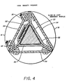
- FIG 4 a high density electronic packaging system utilizing the heat absorbing material principles of the present invention is illustrated in transverse cross-sectional view.
- the circle 51 represents the interior circumference of the outer pressure housing or vacuum flask of the well logging tool as previously discussed.
- A-flanged triangularly cross- sectioned longitudinally extensive support member 52 having a hollow interior portion filled with a heat absorbing material 53 on its interior walls is shown in Figure 4.
- Circuit boards 54 may be mounted along each of the three sides of the interior triangular shaped portion of the support member 52 as shown.
- This packaging technique permits the use of an additional circuit board which may run longitudinally along the entire length of the logging tool and hence provides greater electronic density of packaging than the embodiments shown in Figure 2 and Figure 3.
- the circuit boards 54 of Figure 4 are attached to the center support member structure 52 by conventional mounting means 55 affixed to tabs which may be, for example, punched at intervals along the support member 52 length and bent outwardly therefrom. It will be noted that in the embodiment shown in Figure 4 of the support member structure that the circuit boards 54 are in intimate electrical and thermal contact with the walls of the support member 52 along their entire length. The heat load from each of the circuit boards 54 may thus be readily conducted through the mounting means to the structural support member 52.
- the hollow interior portion of the structural support member 52 is provided with "slide in” or insertable heat absorber modules 53 which may be inserted longitudinally along the axis of the support member 52 as desired. Non-heat absorbing spacers may be utilized, if desired, along portions of the structure 52 which do not carry electronic component mounted on the circuit boards 54.
Landscapes
- Engineering & Computer Science (AREA)
- Physics & Mathematics (AREA)
- Mining & Mineral Resources (AREA)
- Geology (AREA)
- Life Sciences & Earth Sciences (AREA)
- General Life Sciences & Earth Sciences (AREA)
- Fluid Mechanics (AREA)
- Environmental & Geological Engineering (AREA)
- Thermal Sciences (AREA)
- Microelectronics & Electronic Packaging (AREA)
- Geochemistry & Mineralogy (AREA)
- Mechanical Engineering (AREA)
- General Engineering & Computer Science (AREA)
- Geophysics (AREA)
- Cooling Or The Like Of Electrical Apparatus (AREA)
- Cooling Or The Like Of Semiconductors Or Solid State Devices (AREA)
- Gas Or Oil Filled Cable Accessories (AREA)
Applications Claiming Priority (2)
| Application Number | Priority Date | Filing Date | Title |
|---|---|---|---|
| US06/389,659 US4479383A (en) | 1982-06-18 | 1982-06-18 | Borehole apparatus for thermal equalization |
| US389659 | 1982-06-18 |
Publications (2)
| Publication Number | Publication Date |
|---|---|
| EP0097433A2 true EP0097433A2 (de) | 1984-01-04 |
| EP0097433A3 EP0097433A3 (de) | 1985-12-18 |
Family
ID=23539175
Family Applications (1)
| Application Number | Title | Priority Date | Filing Date |
|---|---|---|---|
| EP83303011A Withdrawn EP0097433A3 (de) | 1982-06-18 | 1983-05-25 | Vorrichtung zum Schützen von elektrischen Bestandteilen in Hochtemperaturbohrlöchern |
Country Status (5)
| Country | Link |
|---|---|
| US (1) | US4479383A (de) |
| EP (1) | EP0097433A3 (de) |
| AU (1) | AU1588783A (de) |
| BR (1) | BR8303130A (de) |
| CA (1) | CA1194782A (de) |
Cited By (6)
| Publication number | Priority date | Publication date | Assignee | Title |
|---|---|---|---|---|
| EP0148694A1 (de) * | 1983-12-23 | 1985-07-17 | Schlumberger Technology Corporation | Vorrichtung zur Aufnahme electronischer Baugruppen |
| EP0183024A3 (en) * | 1984-11-30 | 1988-07-27 | Degussa Aktiengesellschaft | Apparatus for the avoidance of local overheating of measuring transducers |
| EP1828539B1 (de) * | 2004-12-03 | 2013-01-16 | Halliburton Energy Services, Inc. | Erwärmen und kühlen von elektrischen bauteilen in einem bohrlochbetrieb |
| CN108594950A (zh) * | 2013-06-07 | 2018-09-28 | 苹果公司 | 计算机内部体系结构 |
| US11256307B2 (en) | 2013-06-07 | 2022-02-22 | Apple Inc. | Desktop electronic device |
| CN116792087A (zh) * | 2023-08-22 | 2023-09-22 | 太原理工大学 | 一种测量深层高温地热井井底地热流体温度的装置及方法 |
Families Citing this family (15)
| Publication number | Priority date | Publication date | Assignee | Title |
|---|---|---|---|---|
| US4618197A (en) * | 1985-06-19 | 1986-10-21 | Halliburton Company | Exoskeletal packaging scheme for circuit boards |
| CN2269463Y (zh) * | 1996-06-07 | 1997-12-03 | 辽河石油勘探局钻采工艺研究院 | 高温高压四参数测试仪 |
| GB2377750B (en) * | 2001-04-03 | 2003-07-30 | Calidus Ltd | Thermal control units |
| US6621702B2 (en) * | 2002-01-25 | 2003-09-16 | Lockheed Martin Corporation | Method and apparatus for absorbing thermal energy |
| US7246940B2 (en) * | 2003-06-24 | 2007-07-24 | Halliburton Energy Services, Inc. | Method and apparatus for managing the temperature of thermal components |
| US7116555B2 (en) * | 2003-12-29 | 2006-10-03 | International Business Machines Corporation | Acoustic and thermal energy management system |
| US20090014166A1 (en) * | 2007-07-09 | 2009-01-15 | Baker Hughes Incorporated | Shock absorption for a logging instrument |
| US8631867B2 (en) * | 2008-12-23 | 2014-01-21 | Halliburton Energy Services, Inc. | Methods for cooling measuring devices in high temperature wells |
| EP2929137A1 (de) | 2012-12-06 | 2015-10-14 | Evolution Engineering Inc. | Montage- und bauteilhaltervorrichtungen und baugruppen zur aufnahme von steifen komponenten |
| US10729029B2 (en) | 2012-12-06 | 2020-07-28 | Evolution Engineering Inc. | Mounting and component holder apparatuses and assemblies for holding rigid components |
| US11899509B2 (en) | 2013-06-07 | 2024-02-13 | Apple Inc. | Computer housing |
| US10012036B2 (en) * | 2014-09-19 | 2018-07-03 | Halliburton Energy Services, Inc. | Downhole electronic assemblies |
| ES2733979T3 (es) * | 2016-03-01 | 2019-12-03 | Adventys | Calefacción por inducción magnética con espaciador |
| US10787897B2 (en) * | 2016-12-22 | 2020-09-29 | Baker Hughes Holdings Llc | Electronic module housing for downhole use |
| US12464647B2 (en) * | 2020-12-24 | 2025-11-04 | Sk Hynix Nand Product Solutions Corp. | Triangular board assembly for solid state drive |
Family Cites Families (6)
| Publication number | Priority date | Publication date | Assignee | Title |
|---|---|---|---|---|
| FR1406819A (fr) * | 1964-08-26 | 1965-07-23 | Jersey Prod Res Co | Procédé et dispositif de stabilisation de la température des détecteurs de radiations |
| US3379032A (en) * | 1965-12-21 | 1968-04-23 | Dresser Ind | Temperature stabilization apparatus for well logging systems |
| AU533206B2 (en) * | 1979-06-21 | 1983-11-10 | Schlumberger Technology B.V. | Cryostats for photon detectors |
| US4302886A (en) * | 1979-10-29 | 1981-12-01 | Robert L. Fournet | Gyroscopic directional surveying instrument |
| US4377198A (en) * | 1980-10-14 | 1983-03-22 | Motorola Inc. | Passive, recyclable cooling system for missile electronics |
| US4430691A (en) * | 1981-02-23 | 1984-02-07 | Sperry Corporation | Electromechanical display instrument assembly |
-
1982
- 1982-06-18 US US06/389,659 patent/US4479383A/en not_active Expired - Fee Related
-
1983
- 1983-05-25 EP EP83303011A patent/EP0097433A3/de not_active Withdrawn
- 1983-06-10 CA CA000430131A patent/CA1194782A/en not_active Expired
- 1983-06-13 BR BR8303130A patent/BR8303130A/pt unknown
- 1983-06-17 AU AU15887/83A patent/AU1588783A/en not_active Abandoned
Cited By (12)
| Publication number | Priority date | Publication date | Assignee | Title |
|---|---|---|---|---|
| EP0148694A1 (de) * | 1983-12-23 | 1985-07-17 | Schlumberger Technology Corporation | Vorrichtung zur Aufnahme electronischer Baugruppen |
| EP0183024A3 (en) * | 1984-11-30 | 1988-07-27 | Degussa Aktiengesellschaft | Apparatus for the avoidance of local overheating of measuring transducers |
| EP1828539B1 (de) * | 2004-12-03 | 2013-01-16 | Halliburton Energy Services, Inc. | Erwärmen und kühlen von elektrischen bauteilen in einem bohrlochbetrieb |
| NO338366B1 (no) * | 2004-12-03 | 2016-08-15 | Halliburton Energy Services Inc | Anordning og fremgangsmåte for varming og kjøling av elektriske komponenter i en borehullsoperasjon |
| CN108594950A (zh) * | 2013-06-07 | 2018-09-28 | 苹果公司 | 计算机内部体系结构 |
| CN108594950B (zh) * | 2013-06-07 | 2021-10-29 | 苹果公司 | 计算机内部体系结构 |
| US11256307B2 (en) | 2013-06-07 | 2022-02-22 | Apple Inc. | Desktop electronic device |
| US11650634B2 (en) | 2013-06-07 | 2023-05-16 | Apple Inc. | Desktop electronic device |
| US12050494B2 (en) | 2013-06-07 | 2024-07-30 | Apple Inc. | Desktop electronic device |
| US12321205B2 (en) | 2013-06-07 | 2025-06-03 | Apple Inc. | Desktop electronic device |
| CN116792087A (zh) * | 2023-08-22 | 2023-09-22 | 太原理工大学 | 一种测量深层高温地热井井底地热流体温度的装置及方法 |
| CN116792087B (zh) * | 2023-08-22 | 2023-11-21 | 太原理工大学 | 一种测量深层高温地热井井底地热流体温度的装置及方法 |
Also Published As
| Publication number | Publication date |
|---|---|
| US4479383A (en) | 1984-10-30 |
| BR8303130A (pt) | 1984-01-31 |
| EP0097433A3 (de) | 1985-12-18 |
| AU1588783A (en) | 1986-11-27 |
| CA1194782A (en) | 1985-10-08 |
Similar Documents
| Publication | Publication Date | Title |
|---|---|---|
| US4479383A (en) | Borehole apparatus for thermal equalization | |
| US5305184A (en) | Method and apparatus for immersion cooling or an electronic board | |
| EP3240386A1 (de) | Wärmekapazitätssystem | |
| US4513352A (en) | Thermal protection apparatus | |
| US9909816B2 (en) | Thermal management system | |
| US6019167A (en) | Liquid immersion cooling apparatus for electronic systems operating in thermally uncontrolled environments | |
| US4167771A (en) | Thermal interface adapter for a conduction cooling module | |
| US4145708A (en) | Power module with isolated substrates cooled by integral heat-energy-removal means | |
| Junior et al. | Thermal performance of a novel flat thermosyphon for avionics thermal management | |
| US3532158A (en) | Thermal control structure | |
| Cao et al. | Wickless network heat pipes for high heat flux spreading applications | |
| US20040264543A1 (en) | Method and apparatus for managing the temperature of thermal components | |
| US4616699A (en) | Wick-fin heat pipe | |
| WO1996028846A1 (en) | Heat sink | |
| US6978828B1 (en) | Heat pipe cooling system | |
| US4921043A (en) | Shelter device for the production and thermal conditioning of apparatus, in particular electronic apparatus generating heat | |
| CN105952440A (zh) | 井下电子仪器强制冷却保温舱 | |
| US4671349A (en) | Well logging electronics cooling system | |
| EP0129954A1 (de) | Passives Temperaturregelsystem | |
| US2787744A (en) | Temperature stabilized transistor | |
| JPS56127143A (en) | Heat pipe type subterranean heat pickup apparatus | |
| SU1721862A1 (ru) | Радиоэлектронный блок | |
| KR100622951B1 (ko) | 온수관 포설용 난방패널 | |
| WO2025117618A1 (en) | Thermally insulated container having hybrid material plug and well intervention tool made therewith | |
| SU963758A2 (ru) | Горелка дл дуговой сварки неплав щимс электродом в среде защитных газов |
Legal Events
| Date | Code | Title | Description |
|---|---|---|---|
| PUAI | Public reference made under article 153(3) epc to a published international application that has entered the european phase |
Free format text: ORIGINAL CODE: 0009012 |
|
| AK | Designated contracting states |
Designated state(s): DE FR GB IT NL |
|
| PUAL | Search report despatched |
Free format text: ORIGINAL CODE: 0009013 |
|
| AK | Designated contracting states |
Designated state(s): DE FR GB IT NL |
|
| STAA | Information on the status of an ep patent application or granted ep patent |
Free format text: STATUS: THE APPLICATION IS DEEMED TO BE WITHDRAWN |
|
| 18D | Application deemed to be withdrawn |
Effective date: 19860819 |
|
| RIN1 | Information on inventor provided before grant (corrected) |
Inventor name: BRAVENEC, FRANK RICHARD |