EP0097084B1 - Machine à cycle de Stirling - Google Patents
Machine à cycle de Stirling Download PDFInfo
- Publication number
- EP0097084B1 EP0097084B1 EP83401136A EP83401136A EP0097084B1 EP 0097084 B1 EP0097084 B1 EP 0097084B1 EP 83401136 A EP83401136 A EP 83401136A EP 83401136 A EP83401136 A EP 83401136A EP 0097084 B1 EP0097084 B1 EP 0097084B1
- Authority
- EP
- European Patent Office
- Prior art keywords
- chamber
- piston
- swash plate
- housing
- shaft
- Prior art date
- Legal status (The legal status is an assumption and is not a legal conclusion. Google has not performed a legal analysis and makes no representation as to the accuracy of the status listed.)
- Expired
Links
- 230000009347 mechanical transmission Effects 0.000 claims abstract description 11
- 230000002093 peripheral effect Effects 0.000 claims description 7
- 230000001050 lubricating effect Effects 0.000 claims description 6
- 210000001699 lower leg Anatomy 0.000 claims 6
- 239000007789 gas Substances 0.000 claims 3
- 239000010687 lubricating oil Substances 0.000 claims 1
- 239000012530 fluid Substances 0.000 description 7
- 238000007789 sealing Methods 0.000 description 6
- 239000000463 material Substances 0.000 description 4
- 230000001172 regenerating effect Effects 0.000 description 4
- 238000011109 contamination Methods 0.000 description 3
- 238000005461 lubrication Methods 0.000 description 3
- 230000001131 transforming effect Effects 0.000 description 3
- OKTJSMMVPCPJKN-UHFFFAOYSA-N Carbon Chemical compound [C] OKTJSMMVPCPJKN-UHFFFAOYSA-N 0.000 description 1
- 229910000831 Steel Inorganic materials 0.000 description 1
- 230000001133 acceleration Effects 0.000 description 1
- 230000004888 barrier function Effects 0.000 description 1
- 230000005540 biological transmission Effects 0.000 description 1
- 229910052799 carbon Inorganic materials 0.000 description 1
- 238000006243 chemical reaction Methods 0.000 description 1
- 230000006835 compression Effects 0.000 description 1
- 238000007906 compression Methods 0.000 description 1
- 238000010276 construction Methods 0.000 description 1
- 230000006866 deterioration Effects 0.000 description 1
- 238000006073 displacement reaction Methods 0.000 description 1
- 230000000694 effects Effects 0.000 description 1
- 239000004519 grease Substances 0.000 description 1
- 230000003100 immobilizing effect Effects 0.000 description 1
- 239000007788 liquid Substances 0.000 description 1
- 239000000314 lubricant Substances 0.000 description 1
- 238000012423 maintenance Methods 0.000 description 1
- 239000000203 mixture Substances 0.000 description 1
- 230000010355 oscillation Effects 0.000 description 1
- 239000002245 particle Substances 0.000 description 1
- 230000010363 phase shift Effects 0.000 description 1
- 238000005057 refrigeration Methods 0.000 description 1
- 238000005096 rolling process Methods 0.000 description 1
- 239000010959 steel Substances 0.000 description 1
- 239000000126 substance Substances 0.000 description 1
Images


Classifications
-
- F—MECHANICAL ENGINEERING; LIGHTING; HEATING; WEAPONS; BLASTING
- F02—COMBUSTION ENGINES; HOT-GAS OR COMBUSTION-PRODUCT ENGINE PLANTS
- F02G—HOT GAS OR COMBUSTION-PRODUCT POSITIVE-DISPLACEMENT ENGINE PLANTS; USE OF WASTE HEAT OF COMBUSTION ENGINES; NOT OTHERWISE PROVIDED FOR
- F02G1/00—Hot gas positive-displacement engine plants
- F02G1/04—Hot gas positive-displacement engine plants of closed-cycle type
- F02G1/043—Hot gas positive-displacement engine plants of closed-cycle type the engine being operated by expansion and contraction of a mass of working gas which is heated and cooled in one of a plurality of constantly communicating expansible chambers, e.g. Stirling cycle type engines
- F02G1/053—Component parts or details
- F02G1/0535—Seals or sealing arrangements
-
- F—MECHANICAL ENGINEERING; LIGHTING; HEATING; WEAPONS; BLASTING
- F02—COMBUSTION ENGINES; HOT-GAS OR COMBUSTION-PRODUCT ENGINE PLANTS
- F02G—HOT GAS OR COMBUSTION-PRODUCT POSITIVE-DISPLACEMENT ENGINE PLANTS; USE OF WASTE HEAT OF COMBUSTION ENGINES; NOT OTHERWISE PROVIDED FOR
- F02G1/00—Hot gas positive-displacement engine plants
- F02G1/04—Hot gas positive-displacement engine plants of closed-cycle type
- F02G1/043—Hot gas positive-displacement engine plants of closed-cycle type the engine being operated by expansion and contraction of a mass of working gas which is heated and cooled in one of a plurality of constantly communicating expansible chambers, e.g. Stirling cycle type engines
- F02G1/044—Hot gas positive-displacement engine plants of closed-cycle type the engine being operated by expansion and contraction of a mass of working gas which is heated and cooled in one of a plurality of constantly communicating expansible chambers, e.g. Stirling cycle type engines having at least two working members, e.g. pistons, delivering power output
-
- F—MECHANICAL ENGINEERING; LIGHTING; HEATING; WEAPONS; BLASTING
- F16—ENGINEERING ELEMENTS AND UNITS; GENERAL MEASURES FOR PRODUCING AND MAINTAINING EFFECTIVE FUNCTIONING OF MACHINES OR INSTALLATIONS; THERMAL INSULATION IN GENERAL
- F16J—PISTONS; CYLINDERS; SEALINGS
- F16J15/00—Sealings
- F16J15/50—Sealings between relatively-movable members, by means of a sealing without relatively-moving surfaces, e.g. fluid-tight sealings for transmitting motion through a wall
- F16J15/52—Sealings between relatively-movable members, by means of a sealing without relatively-moving surfaces, e.g. fluid-tight sealings for transmitting motion through a wall by means of sealing bellows or diaphragms
- F16J15/525—Sealings between relatively-movable members, by means of a sealing without relatively-moving surfaces, e.g. fluid-tight sealings for transmitting motion through a wall by means of sealing bellows or diaphragms fixed to a part of a transmission performing a wobbling or a circular translatory movement
-
- F—MECHANICAL ENGINEERING; LIGHTING; HEATING; WEAPONS; BLASTING
- F02—COMBUSTION ENGINES; HOT-GAS OR COMBUSTION-PRODUCT ENGINE PLANTS
- F02G—HOT GAS OR COMBUSTION-PRODUCT POSITIVE-DISPLACEMENT ENGINE PLANTS; USE OF WASTE HEAT OF COMBUSTION ENGINES; NOT OTHERWISE PROVIDED FOR
- F02G2244/00—Machines having two pistons
- F02G2244/50—Double acting piston machines
-
- F—MECHANICAL ENGINEERING; LIGHTING; HEATING; WEAPONS; BLASTING
- F02—COMBUSTION ENGINES; HOT-GAS OR COMBUSTION-PRODUCT ENGINE PLANTS
- F02G—HOT GAS OR COMBUSTION-PRODUCT POSITIVE-DISPLACEMENT ENGINE PLANTS; USE OF WASTE HEAT OF COMBUSTION ENGINES; NOT OTHERWISE PROVIDED FOR
- F02G2253/00—Seals
- F02G2253/06—Bellow seals
-
- F—MECHANICAL ENGINEERING; LIGHTING; HEATING; WEAPONS; BLASTING
- F02—COMBUSTION ENGINES; HOT-GAS OR COMBUSTION-PRODUCT ENGINE PLANTS
- F02G—HOT GAS OR COMBUSTION-PRODUCT POSITIVE-DISPLACEMENT ENGINE PLANTS; USE OF WASTE HEAT OF COMBUSTION ENGINES; NOT OTHERWISE PROVIDED FOR
- F02G2270/00—Constructional features
- F02G2270/20—Plural piston swash plates
-
- Y—GENERAL TAGGING OF NEW TECHNOLOGICAL DEVELOPMENTS; GENERAL TAGGING OF CROSS-SECTIONAL TECHNOLOGIES SPANNING OVER SEVERAL SECTIONS OF THE IPC; TECHNICAL SUBJECTS COVERED BY FORMER USPC CROSS-REFERENCE ART COLLECTIONS [XRACs] AND DIGESTS
- Y10—TECHNICAL SUBJECTS COVERED BY FORMER USPC
- Y10S—TECHNICAL SUBJECTS COVERED BY FORMER USPC CROSS-REFERENCE ART COLLECTIONS [XRACs] AND DIGESTS
- Y10S277/00—Seal for a joint or juncture
- Y10S277/902—Seal for sterling engine
Definitions
- the present invention relates to machines using a working fluid subjected to a thermodynamic evolution corresponding to the Stirling cycle. These machines are generally used either as motive machines transforming heat energy into mechanical energy, or as heat pump or as refrigeration machine.
- a machine could be designed entirely devoid of lubricated mechanical members, but such a solution would be unsatisfactory, given the complexity of the mechanical transmission necessary to transform the reciprocating movement of the pistons into rotary movement of the machine output shaft. Since, on the other hand, it is practically impossible to produce a total seal between a cylinder and a piston with linear and reciprocating relative movement, positive sealing devices have been envisaged, that is to say using an element deformable which constitutes an absolute barrier to the passage of working gas. These positive sealing devices have however not been entirely satisfactory because of acceleration problems and creating variables from pressure differences and other of étan- G Heite devices, which causes rapid deterioration .
- the present invention relates to a Stirling cycle machine whose arrangement makes it possible to remedy the drawbacks mentioned above.
- the invention relates more particularly to a Stirling cycle machine essentially comprising a casing in which are mounted a rotating shaft, at least three working cylinders arranged parallel around the shaft, a double-acting piston in each of said cylinders, and a transmission mechanical transforming the reciprocating movement of the pistons into the rotating movement of the shaft, consisting of a stationary oscillating plate in rotation, with orbital movement, the axis of which describes a conical surface around the rotating shaft, and articulated links connecting each piston to the swash plate.
- An essential characteristic of the invention resides in the fact that said casing of the machine provides a first chamber in which the rotary shaft is mounted, and a second chamber in which are the articulated connections connecting each piston to the swash plate, and by the fact that an elastic seal is interposed between the casing and the swash plate so as to prevent any communication between the first chamber and the second chamber, and by the fact that each of the articulated connections is mounted in a housing of a linked part rigidly to the piston, the space contained in this housing being isolated from the second chamber by elastic seals connecting the swash plate, in the vicinity of the corresponding connection and the part connected to the corresponding piston.
- This Stirling cycle machine essentially consists of at least three pistons with double effect 4 arranged symmetrically and parallel around the axis of a central rotating shaft 5.
- these pistons 4 are four in number.
- these pistons 4 are driven by a reciprocating movement of the same period and 90 ° phase shift, one relative to the next.
- Each double-acting piston 4 therefore corresponds to first and second chambers 6 and 7, the volume of which varies as a function of the reciprocating movement of the piston.
- Each of these first six chambers communicates with the chamber 7 of the following cylinder by means of a circuit passing successively through a hot source 8, a regenerative exchanger 9, and a cold source 10.
- This Stirling cycle machine has other share a mechanical transmission making it possible to transform the reciprocating movements of the pistons 4 into a movement of rotation of the central shaft 5.
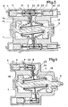
- FIG. 1 there are different essential mechanical elements constituting a machine conforming to the invention.
- the casing 11 of this machine are mounted the rotating shaft 5, the working cylinders 12 arranged in parallel around the shaft, the double-acting pistons 4 arranged in each of the cylinders, and the mechanical transmission connecting the pistons to the rotating shaft.
- the casing 11 provides a first chamber 1 in which the rotary shaft 5 is mounted, and a second chamber 2 in which the mechanical transmission is mounted.
- This mechanical transmission mainly consists of a cylindrical hub 13 to which arms 14 extending radially are rigidly connected.
- each arm 14 is connected to the corresponding piston 4 by means of an articulated connection 15.
- the hub 13 is rotatably mounted around the central part of the rotating shaft 5, the axis of rotation of the hub making a certain angle alpha with the axis of rotation of the shaft 5.
- the assembly constituted by the hub 13 and the arms 14 consequently constitutes a swash plate which can be animated by an orbital movement whose axis describes a surface conical around the axis of the rotating shaft 5.
- This swash plate is however immobilized in rotation using suitable guide elements 16, 17. These elements create the reaction of the casing on the shaft to generate the torque engine. These elements also ensure the correct positioning of the ends of the arms 14 relative to the pistons.
- Chamber 1 is completely isolated from chamber 2 by means of an elastic seal connecting the hub 13 to the casing 11.
- this elastic seal consists of two bellows 18, 19 arranged around the hub 13, l one of the bellows 18 sealingly connecting one end of the hub 13 and a radial web 20 connected to the housing 11, the other bellows 19 sealingly connecting the other end of the hub 13 and another radial web 21 connected to the same housing 11.
- the bellows 18 and 19 can be securely fixed at their two ends, thus guaranteeing an absolute seal.
- the oscillation angle of the hub 13 is relatively small, these bellows undergo movements of small amplitude and can thus resist when the shaft 5 rotates at high speed.
- the chamber 2 cannot receive any dirty particles such as lubricant from the chamber 1.
- each arm 14 of the swash plate is connected to each double-acting piston 4 by means of two thrust rods 15 arranged on either side of the arm 14 and articulated on it using a ball joint connection 22.
- the set of connecting rods 15 and their articulation 22 is disposed in a housing formed in the piston 4 or in a part rigidly connected to this piston 4.
- the chamber 2 is therefore limited, both by the walls of the casing 11, by the seals 3, the bellows 18 and 19, the radial webs 20 and 21, as well as by the external face of the hub 13.
- the seal cannot be perfect between the double-acting piston 4 and the cylinder 1 2 in which it moves alternately, it is always possible that a certain quantity of gas passes from the working chambers 6 and 7 to the chamber 2 and vice versa.
- it is possible to guarantee a perfectly pure atmosphere in the chamber 2, these leaks at the level of the piston 4 do not present any danger of contamination of the working gas contained in the working chambers 6 and 7 It is possible, moreover, to fill the chamber 2 with a gas of composition identical to the working gas.
- the working gas can transit for a very long time through the heat exchangers of the hot source 8, of the regenerative exchanger 9, and of the cold source 10 by guaranteeing that no fatty or other matter comes to deposit on the surfaces of these exchangers, thus guaranteeing for a long period of operation, an efficiency of the heat exchanges and, consequently, the total maintenance machine performance and performance.
- FIG. 3 shows an alternative embodiment.
- the kinematics is perfectly identical to that described above; we find the same isolated rooms 1, 2 and 3; the only difference being in the arrangement of the double-acting piston 4.
- This double-acting piston 4 is not disposed on either side of the articulated connection 22 but is arranged on one side.
- this machine combines both a motor and a pump.
- FIG. 4 represents another variant embodiment in which, as in FIG. 3, the piston 4 is disposed on one side only with respect to the articulated connection, this machine being devoid of another piston disposed on the other side of the articulated link.
- the same housing 3 formed in a part rigidly connected to the double-acting piston 4, isolated from the chamber 2 by means of a seal 23; we also find the same seals 18 and 19 isolating the chamber 1 from the chamber 2.
- the only difference lies in the fact that the connection between the part linked to the piston 4 and the arm 14 is made using a single connecting rod 24 being able to be stressed both in compression and in tension and being connected by articulations to the part linked to the piston 4 and to the ball-shaped end of the arm 14.
- Figure 5 a particularly advantageous construction arrangement of this invention.
- the machine housing made in two parts 11, 11 ', to facilitate assembly.
- this casing there is rotatably mounted a rotating shaft produced in two parts 5, 5 'rigidly assembled, supported by two bearings 25 and 26.
- This machine comprises four double-acting pistons arranged parallel to the axis of the shaft 5, equal distance from this axis and 90 ° to each other.
- Each double-acting piston consists of two parts 25, 26 ensuring sealing by means of segments, these parts being arranged on either side of the articulated connection, and being joined rigidly by means of a rigid connecting part 28.
- the part 26 of the piston disposed on the side of the chamber 6 in communication with the hot source is extended by a cylindrical part 29 with thin walls, forming the head of the piston.
- the other part 27 of the piston is hollow in shape and is closed by a part 30 forming the piston head on the side of the chamber 7.
- the part 26 of the piston also comprises a part 31 in the form of a concave spherical cap in the direction of the articulated connection, and the part 30 fixed inside the part 27 of the piston also has a concave spherical surface in the direction of the articulated connection. On the spherical surfaces of the two parts 30 and 31 come to bear respectively two thrust rods 15 and 15 '.
- the other end of these connecting rods 15 and 15 'each has a concave spherical face in which is housed a spherical part 32 made in two parts mounted on the peripheral end of the corresponding radial arm 14.
- the oscillating plate therefore comprises the four arms radial 14 corresponding to the four double-acting pistons, these radial arms being rigidly connected to the cylindrical hub 13 which surrounds the central part of the rotating shaft 5, with interposition between the hub 13 and the shaft 5 of rolling bearings 33, 34
- the bellows 18 surrounds the hub 13, has one end rigidly connected to one end of the hub 13, and has its other end rigidly connected to the circular edge of an annular piece 20, the peripheral part of which is rigidly fixed on the casing 11.
- the bellows 19 is mounted identically on the hub 13 and connects the other end of this hub 13 and the edge of a part 21 arranged symmetrically with respect to the part 20.
- the spherical part 32 mounted on the end of the swash plate is driven by a slight movement relative to the pistons. Consequently, it follows a slight pivoting of the connecting rods 15 and 15 'relative to the ball joint 32 and relative to the corresponding parts 31 and 30 linked to the double-acting piston. Given the small amplitude of the relative displacements between the connecting rods and the parts 31 and 30, it is expected that the corresponding friction surfaces will not be lubricated. To avoid any wear, the materials of these parts can be chosen so that friction takes place, for example, between a steel surface and a carbon surface.
- This sealing device is constituted by the two bellows seals 23 and 23 ′, the bellows seal 23 sealingly connecting the thrust rod 15 and a peripheral zone of the spherical part 32 linked to the swash plate, the other bellows seal 23 'sealingly connecting the other thrust rod 15' and a peripheral zone of the spherical part 32.
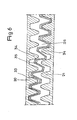
- This device for immobilizing the swash plate in rotation can advantageously be produced by constituting, around the hub 13, a portion 33 extending radially outwards, having on each side notches 35 which can engage in corresponding teeth 34 arranged respectively on the two parts 20 and 21.
- Figure 6 which shows a developed section established at a cylindrical surface passing through AA extended approximately_ on a half-turn of the machine, we can see in detail the constructive arrangement of the part 33 of the swash plate cooperating respectively with the teeth of the parts 20 and 21.
- the part 33 of the swash plate has a wavy shape constituting on both sides of the teeth, and, in general, it can be said that the parts 20 and 21 have teeth 34 arranged so as to form a conical pinion with an apex that is substantially comfortable. ndu with center 0, and it is the same for the teeth located on either side of part 33 of the swash plate.
- the number of teeth of the swash plate is equal to the number of teeth 34 of parts 20 and 21.
Landscapes
- Engineering & Computer Science (AREA)
- General Engineering & Computer Science (AREA)
- Mechanical Engineering (AREA)
- Chemical & Material Sciences (AREA)
- Combustion & Propulsion (AREA)
- Compressors, Vaccum Pumps And Other Relevant Systems (AREA)
- Sealing Devices (AREA)
- Medicines Containing Plant Substances (AREA)
- Pyrane Compounds (AREA)
- Massaging Devices (AREA)
- Hydraulic Motors (AREA)
Priority Applications (1)
| Application Number | Priority Date | Filing Date | Title |
|---|---|---|---|
| AT83401136T ATE19677T1 (de) | 1982-06-04 | 1983-06-03 | Stirling-kreislaufmaschine. |
Applications Claiming Priority (2)
| Application Number | Priority Date | Filing Date | Title |
|---|---|---|---|
| FR8209776A FR2528109A1 (fr) | 1982-06-04 | 1982-06-04 | Machine a cycle de stirling |
| FR8209776 | 1982-06-04 |
Publications (2)
| Publication Number | Publication Date |
|---|---|
| EP0097084A1 EP0097084A1 (fr) | 1983-12-28 |
| EP0097084B1 true EP0097084B1 (fr) | 1986-05-07 |
Family
ID=9274653
Family Applications (1)
| Application Number | Title | Priority Date | Filing Date |
|---|---|---|---|
| EP83401136A Expired EP0097084B1 (fr) | 1982-06-04 | 1983-06-03 | Machine à cycle de Stirling |
Country Status (6)
| Country | Link |
|---|---|
| US (1) | US4495771A (enExample) |
| EP (1) | EP0097084B1 (enExample) |
| JP (1) | JPS593150A (enExample) |
| AT (1) | ATE19677T1 (enExample) |
| DE (1) | DE3363373D1 (enExample) |
| FR (1) | FR2528109A1 (enExample) |
Families Citing this family (8)
| Publication number | Priority date | Publication date | Assignee | Title |
|---|---|---|---|---|
| US4794752A (en) * | 1987-05-14 | 1989-01-03 | Redderson Roy H | Vapor stirling heat machine |
| GB9008523D0 (en) * | 1990-04-17 | 1990-06-13 | Energy For Suitable Dev Limite | Reciprocatory displacement machine |
| JPH05231240A (ja) * | 1992-02-21 | 1993-09-07 | Toyota Autom Loom Works Ltd | 両頭斜板式スターリング機関 |
| GB2296047B (en) * | 1994-12-15 | 1998-04-08 | Jonathan Maxwell Boardman | Diaphragm stirling engine |
| LT4296B (lt) * | 1996-04-26 | 1998-02-25 | Simonas Narbutas | Regeneracinės stūmoklinės šiluminės mašinos veikimo būdas ir regeneracinė stūmoklinė šiluminė mašina |
| US20030145835A1 (en) * | 2002-02-05 | 2003-08-07 | Stanadyne Corporation | Drive shaft seal for gasoline direct injection pump |
| GB0210929D0 (en) * | 2002-05-13 | 2002-06-19 | Bg Intellectual Pty Ltd | A stirling engine assembly |
| CN111765001B (zh) * | 2020-06-28 | 2021-08-27 | 重庆交通大学绿色航空技术研究院 | 轴协同三维摆盘活塞发动机 |
Citations (1)
| Publication number | Priority date | Publication date | Assignee | Title |
|---|---|---|---|---|
| US4152945A (en) * | 1976-04-21 | 1979-05-08 | Vadetec Corporation | Power transmitting mechanism |
Family Cites Families (11)
| Publication number | Priority date | Publication date | Assignee | Title |
|---|---|---|---|---|
| DE491226C (de) * | 1925-04-29 | 1930-02-07 | Alfred Arthur Quick | Kurbellose Kolbenmaschine |
| US1807139A (en) * | 1926-09-13 | 1931-05-26 | Nicholas N Volodimirov | Flexible packing |
| FR941997A (fr) * | 1946-02-21 | 1949-01-26 | Philips Nv | Bielle pour mécanisme à disque de mutation |
| US3164389A (en) * | 1960-11-22 | 1965-01-05 | American Metal Prod | Seal for ball joint stud |
| FR1376714A (fr) * | 1963-09-17 | 1964-10-31 | Hispano Suiza Sa | Perfectionnements apportés aux compresseurs volumétriques alternatifs hermétiques, notamment à ceux à pistons |
| US3306134A (en) * | 1964-04-24 | 1967-02-28 | Trw Inc | Wabble gear drive mechanism |
| NL7210087A (enExample) * | 1972-07-21 | 1974-01-23 | ||
| US4080788A (en) * | 1976-07-06 | 1978-03-28 | Ford Motor Company | Separator apparatus for differential high pressure systems of a Stirling engine |
| NL7608350A (nl) * | 1976-07-28 | 1978-01-31 | Philips Nv | Drijfwerk. |
| US4381648A (en) * | 1980-12-29 | 1983-05-03 | North American Philips Corporation | Stirling cycle apparatus with metal bellows seal |
| US4372116A (en) * | 1981-01-26 | 1983-02-08 | Mechanical Technology Incorporated | Stirling engine control mechanism and method |
-
1982
- 1982-06-04 FR FR8209776A patent/FR2528109A1/fr active Granted
-
1983
- 1983-04-11 US US06/484,029 patent/US4495771A/en not_active Expired - Fee Related
- 1983-06-03 DE DE8383401136T patent/DE3363373D1/de not_active Expired
- 1983-06-03 EP EP83401136A patent/EP0097084B1/fr not_active Expired
- 1983-06-03 AT AT83401136T patent/ATE19677T1/de active
- 1983-06-04 JP JP58100121A patent/JPS593150A/ja active Granted
Patent Citations (1)
| Publication number | Priority date | Publication date | Assignee | Title |
|---|---|---|---|---|
| US4152945A (en) * | 1976-04-21 | 1979-05-08 | Vadetec Corporation | Power transmitting mechanism |
Also Published As
| Publication number | Publication date |
|---|---|
| US4495771A (en) | 1985-01-29 |
| DE3363373D1 (en) | 1986-06-12 |
| FR2528109B1 (enExample) | 1985-02-22 |
| JPH0585744B2 (enExample) | 1993-12-08 |
| ATE19677T1 (de) | 1986-05-15 |
| FR2528109A1 (fr) | 1983-12-09 |
| EP0097084A1 (fr) | 1983-12-28 |
| JPS593150A (ja) | 1984-01-09 |
Similar Documents
| Publication | Publication Date | Title |
|---|---|---|
| FR2523700A1 (fr) | Appareil de refroidissement cryogenique de petite dimension | |
| FR2780450A1 (fr) | Moteur hydraulique compact | |
| FR2519699A1 (fr) | Moteur a piston a mouvement alternatif avec mecanisme a plateau en nutation | |
| EP0097084A1 (fr) | Machine à cycle de Stirling | |
| CA2949729C (fr) | Raccord d'etancheite tournant haute-pression a bague continue extensible | |
| EP0114781B1 (fr) | Machine thermique à source d'énergie externe ou interne aux cylindres du type compresseur ou moteur à cycle de Stirling par exemple | |
| FR2529988A1 (fr) | Garniture d'etancheite du type a labyrinthe, notamment pour des machines tournantes telles que pompes ou analogues | |
| EP0627042B1 (fr) | Machine volumetrique a pistons louvoyants, en particulier moteur a quatre temps | |
| EP0426540B1 (fr) | Moteur à combustion interne à rapport volumétrique variable | |
| EP3698045A1 (fr) | Pompe a barillet rotatif avec double plateaux | |
| CH645698A5 (fr) | Machine a chambres et pistons oscillants. | |
| EP0778452A1 (fr) | Refroidisseur stirling à pilotage rotatif | |
| EP3698062A1 (fr) | Dispositif de forme spherique et muni de cannelures bombees pour former une liaison rotule a doigt, et pompe a barillet muni d'un tel dispositif | |
| FR2604489A1 (fr) | Dispositif a fluide du type a disque a mouvement de nutation | |
| EP3045656B1 (fr) | Machine rotative a losange deformable multifonctions | |
| EP3698044B1 (fr) | Pompe a barillet rotatif avec moyens de guidage et de centrage du barillet distincts | |
| FR3132737A1 (fr) | Moteur thermique alternatif | |
| EP0127694B1 (fr) | Machine à chambres et pistons oscillants | |
| FR2551832A1 (fr) | Perfectionnements apportes aux raccords tournants | |
| FR2511729A1 (fr) | Machine a cycle stirling | |
| FR2496162A1 (fr) | Turbine a refoulement | |
| FR2701736A1 (fr) | Mécanisme à fluide sous pression comportant des plots tubulaires, tel qu'un moteur ou une pompe hydraulique. | |
| CA3056167A1 (fr) | Pompe a double plateau et double barillet | |
| FR2478195A1 (fr) | Mecanisme de transmission du mouvement des pistons d'un moteur | |
| FR2806750A1 (fr) | Machine motrice et receptrice a mouvement rotatif |
Legal Events
| Date | Code | Title | Description |
|---|---|---|---|
| PUAI | Public reference made under article 153(3) epc to a published international application that has entered the european phase |
Free format text: ORIGINAL CODE: 0009012 |
|
| AK | Designated contracting states |
Designated state(s): AT BE CH DE FR GB IT LI LU NL SE |
|
| 17P | Request for examination filed |
Effective date: 19831209 |
|
| GRAA | (expected) grant |
Free format text: ORIGINAL CODE: 0009210 |
|
| AK | Designated contracting states |
Kind code of ref document: B1 Designated state(s): AT BE CH DE FR GB IT LI LU NL SE |
|
| PG25 | Lapsed in a contracting state [announced via postgrant information from national office to epo] |
Ref country code: AT Effective date: 19860507 |
|
| REF | Corresponds to: |
Ref document number: 19677 Country of ref document: AT Date of ref document: 19860515 Kind code of ref document: T |
|
| REF | Corresponds to: |
Ref document number: 3363373 Country of ref document: DE Date of ref document: 19860612 |
|
| PG25 | Lapsed in a contracting state [announced via postgrant information from national office to epo] |
Ref country code: LU Free format text: LAPSE BECAUSE OF NON-PAYMENT OF DUE FEES Effective date: 19860630 |
|
| ITF | It: translation for a ep patent filed | ||
| RAP2 | Party data changed (patent owner data changed or rights of a patent transferred) |
Owner name: FRAMATOME |
|
| BECN | Be: change of holder's name |
Effective date: 19860507 |
|
| NLT2 | Nl: modifications (of names), taken from the european patent patent bulletin |
Owner name: FRAMATOME TE COURBEVOIE, FRANKRIJK. |
|
| REG | Reference to a national code |
Ref country code: FR Ref legal event code: ST |
|
| REG | Reference to a national code |
Ref country code: FR Ref legal event code: AR |
|
| PLBE | No opposition filed within time limit |
Free format text: ORIGINAL CODE: 0009261 |
|
| STAA | Information on the status of an ep patent application or granted ep patent |
Free format text: STATUS: NO OPPOSITION FILED WITHIN TIME LIMIT |
|
| REG | Reference to a national code |
Ref country code: FR Ref legal event code: BR |
|
| 26N | No opposition filed | ||
| ITTA | It: last paid annual fee | ||
| EAL | Se: european patent in force in sweden |
Ref document number: 83401136.3 |
|
| PGFP | Annual fee paid to national office [announced via postgrant information from national office to epo] |
Ref country code: GB Payment date: 19950616 Year of fee payment: 13 |
|
| PG25 | Lapsed in a contracting state [announced via postgrant information from national office to epo] |
Ref country code: GB Effective date: 19960603 |
|
| GBPC | Gb: european patent ceased through non-payment of renewal fee |
Effective date: 19960603 |
|
| PGFP | Annual fee paid to national office [announced via postgrant information from national office to epo] |
Ref country code: SE Payment date: 19970528 Year of fee payment: 15 |
|
| PGFP | Annual fee paid to national office [announced via postgrant information from national office to epo] |
Ref country code: BE Payment date: 19970530 Year of fee payment: 15 |
|
| PGFP | Annual fee paid to national office [announced via postgrant information from national office to epo] |
Ref country code: DE Payment date: 19970604 Year of fee payment: 15 |
|
| PGFP | Annual fee paid to national office [announced via postgrant information from national office to epo] |
Ref country code: CH Payment date: 19970610 Year of fee payment: 15 |
|
| PGFP | Annual fee paid to national office [announced via postgrant information from national office to epo] |
Ref country code: NL Payment date: 19970630 Year of fee payment: 15 |
|
| REG | Reference to a national code |
Ref country code: FR Ref legal event code: TQ Ref country code: FR Ref legal event code: TP |
|
| PG25 | Lapsed in a contracting state [announced via postgrant information from national office to epo] |
Ref country code: SE Free format text: LAPSE BECAUSE OF NON-PAYMENT OF DUE FEES Effective date: 19980604 |
|
| PG25 | Lapsed in a contracting state [announced via postgrant information from national office to epo] |
Ref country code: LI Free format text: LAPSE BECAUSE OF NON-PAYMENT OF DUE FEES Effective date: 19980630 Ref country code: CH Free format text: LAPSE BECAUSE OF NON-PAYMENT OF DUE FEES Effective date: 19980630 Ref country code: BE Free format text: LAPSE BECAUSE OF NON-PAYMENT OF DUE FEES Effective date: 19980630 |
|
| BERE | Be: lapsed |
Owner name: FRAMATOME Effective date: 19980630 |
|
| PG25 | Lapsed in a contracting state [announced via postgrant information from national office to epo] |
Ref country code: NL Free format text: LAPSE BECAUSE OF NON-PAYMENT OF DUE FEES Effective date: 19990101 |
|
| REG | Reference to a national code |
Ref country code: CH Ref legal event code: PL |
|
| EUG | Se: european patent has lapsed |
Ref document number: 83401136.3 |
|
| NLV4 | Nl: lapsed or anulled due to non-payment of the annual fee |
Effective date: 19990101 |
|
| PG25 | Lapsed in a contracting state [announced via postgrant information from national office to epo] |
Ref country code: DE Free format text: LAPSE BECAUSE OF NON-PAYMENT OF DUE FEES Effective date: 19990601 |
|
| PGFP | Annual fee paid to national office [announced via postgrant information from national office to epo] |
Ref country code: FR Payment date: 19991227 Year of fee payment: 17 |
|
| PG25 | Lapsed in a contracting state [announced via postgrant information from national office to epo] |
Ref country code: FR Free format text: LAPSE BECAUSE OF NON-PAYMENT OF DUE FEES Effective date: 20010228 |
|
| REG | Reference to a national code |
Ref country code: FR Ref legal event code: ST |