EP0097082B1 - Dispositif de récupération sélective et continue des hydrocarbures présents sous forme de nappe à la surface d'un milieu aqueux - Google Patents
Dispositif de récupération sélective et continue des hydrocarbures présents sous forme de nappe à la surface d'un milieu aqueux Download PDFInfo
- Publication number
- EP0097082B1 EP0097082B1 EP83401131A EP83401131A EP0097082B1 EP 0097082 B1 EP0097082 B1 EP 0097082B1 EP 83401131 A EP83401131 A EP 83401131A EP 83401131 A EP83401131 A EP 83401131A EP 0097082 B1 EP0097082 B1 EP 0097082B1
- Authority
- EP
- European Patent Office
- Prior art keywords
- vessel
- hydrocarbons
- roller
- rotation
- whereof
- Prior art date
- Legal status (The legal status is an assumption and is not a legal conclusion. Google has not performed a legal analysis and makes no representation as to the accuracy of the status listed.)
- Expired
Links
Images


Classifications
-
- E—FIXED CONSTRUCTIONS
- E02—HYDRAULIC ENGINEERING; FOUNDATIONS; SOIL SHIFTING
- E02B—HYDRAULIC ENGINEERING
- E02B15/00—Cleaning or keeping clear the surface of open water; Apparatus therefor
- E02B15/04—Devices for cleaning or keeping clear the surface of open water from oil or like floating materials by separating or removing these materials
- E02B15/10—Devices for removing the material from the surface
- E02B15/103—Rotary drums
-
- B—PERFORMING OPERATIONS; TRANSPORTING
- B01—PHYSICAL OR CHEMICAL PROCESSES OR APPARATUS IN GENERAL
- B01D—SEPARATION
- B01D17/00—Separation of liquids, not provided for elsewhere, e.g. by thermal diffusion
- B01D17/02—Separation of non-miscible liquids
- B01D17/0208—Separation of non-miscible liquids by sedimentation
- B01D17/0214—Separation of non-miscible liquids by sedimentation with removal of one of the phases
-
- Y—GENERAL TAGGING OF NEW TECHNOLOGICAL DEVELOPMENTS; GENERAL TAGGING OF CROSS-SECTIONAL TECHNOLOGIES SPANNING OVER SEVERAL SECTIONS OF THE IPC; TECHNICAL SUBJECTS COVERED BY FORMER USPC CROSS-REFERENCE ART COLLECTIONS [XRACs] AND DIGESTS
- Y02—TECHNOLOGIES OR APPLICATIONS FOR MITIGATION OR ADAPTATION AGAINST CLIMATE CHANGE
- Y02A—TECHNOLOGIES FOR ADAPTATION TO CLIMATE CHANGE
- Y02A20/00—Water conservation; Efficient water supply; Efficient water use
- Y02A20/20—Controlling water pollution; Waste water treatment
- Y02A20/204—Keeping clear the surface of open water from oil spills
-
- Y—GENERAL TAGGING OF NEW TECHNOLOGICAL DEVELOPMENTS; GENERAL TAGGING OF CROSS-SECTIONAL TECHNOLOGIES SPANNING OVER SEVERAL SECTIONS OF THE IPC; TECHNICAL SUBJECTS COVERED BY FORMER USPC CROSS-REFERENCE ART COLLECTIONS [XRACs] AND DIGESTS
- Y10—TECHNICAL SUBJECTS COVERED BY FORMER USPC
- Y10S—TECHNICAL SUBJECTS COVERED BY FORMER USPC CROSS-REFERENCE ART COLLECTIONS [XRACs] AND DIGESTS
- Y10S210/00—Liquid purification or separation
- Y10S210/918—Miscellaneous specific techniques
- Y10S210/922—Oil spill cleanup, e.g. bacterial
- Y10S210/924—Oil spill cleanup, e.g. bacterial using physical agent, e.g. sponge, mop
Definitions
- the present invention relates to a device for the selective and continuous recovery of the hydrocarbons present in the form of a sheet on the surface of an aqueous medium.
- recuperators The second category of recuperators concerns selective recuperators, that is to say devices which use the properties of certain materials which are both hydrophobic and oleophilic. Such materials are for example described in French patent application 2,390,553 “Purification device for recovering an organic compound in an aqueous medium and their use is described in the above-mentioned manual which provides for a hydrophobic-oleophilic rotary drum associated with a scraper blade allowing the recovery of hydrocarbons.
- Several embodiments are also known in the form of discs, endless bands, as described in patents US-A-3,536,199, US-A-3,693,805, US-A-3,992,292 and CA-A-959423. These recuperators are therefore more or less selective but their use presents several constraints which are penalizing for optimal continuous operation.
- the sheet of hydrocarbons be located in the immediate vicinity of the roller since the latter does not create any surface attracting current.
- the present invention provides a device which allows a selective and continuous recovery of a sheet of hydrocarbons present on the surface of an aqueous medium, this device being simple and compact and also making it possible to attract the sheet to him.
- This device comprises an extraction means constituted by at least one continuous wall set in motion by the rotation, about a horizontal axis, of a drive means, said wall being constituted, at least superficially, by an oleophilic material. and hydrophobic, and being arranged so that its lower part can be in contact with the hydrocarbons to be recovered while its upper part is in contact with a recovery means allowing the recovery of the hydrocarbons which have adhered to the extraction means.
- this device comprises a means of attracting the sheet, making it possible to attract this sheet in the immediate vicinity of the lower part of the continuous wall and to create therein a zone of accumulation of hydrocarbons in which they these are maintained at a substantially constant level.
- This device not only makes it possible to recover the hydrocarbons with a very good yield since these are accumulated at the level of the hydrophobic-oleophilic material but also to attract the sheet to this accumulation zone while preventing any re-mixing of the hydrocarbons with the water.
- hydrophobic and oleophilic material means any material capable of being wetted in the presence of water by the hydrocarbons present in the sheet, while the absence of a polar character prevents it from being wetted by water.
- Such materials are well known to those skilled in the art and can consist, for example, of stainless steel, black steel, aluminum or a plastic material.
- the means of attraction of the sheet consists of a container which has a first, flat face, parallel to the generatrices of a roller constituting the extraction means, and whose upper edge is free, and a second face. , connected to the first by its free edge. These two faces are connected to two lateral, parallel flanges so that the assembly defines a volume, open in its upper part and enveloping at least the lower part of the roller; the container further comprises a means of collecting and discharging the aqueous medium.
- the container is movable in rotation about a horizontal axis between a high position and a low position in which the upper edge of the flat surface is immersed to a depth such that the flow of the fluid entering the container is equal to the sum of the rates of extraction of hydrocarbons by the roller and evacuation of water by the evacuation means.
- the container has an asymmetrical lateral section relative to the plane passing through the axis of rotation, so that the parts of the container situated on either side of this plane have different volumes, the volume before being the smallest.
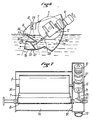
- FIG. 1 shows a device (1) according to the invention installed at one end of a settling tank (2).
- the device (1) comprises a frame (3) placed on the edges (4) of the basin (2), a roller (5), a movable container (6), a scraper blade (7) whose fixed end opens into a recovery gutter (8) to which a flexible pipe (9) is connected, the free end of which opens into a hydrocarbon storage tank (not shown).
- the device further comprises an electric motor (10) powered by the cable (11), and a gear motor (12) fixed on the frame (3).
- Figure 2 shows the device seen from the front. For reasons of clarity, the scraping device comprising the scraper blade (7) and the gutter (8) has not been shown.
- the roller (5) has a cylindrical wall (13) and two side faces (14) and (15).
- the wall (15) is provided with a pin (16) (FIG. 3) engaged in a bore (17) formed in a support (18) screwed to the wall (19) of the frame (3) by the screws (20) and (21).
- the wall (15) also comprises a toothed wheel (22), concentric with the pin (16).
- the wall (14) is mounted in the same way but does not have a toothed wheel.
- the gear motor (12) is held in place on the frame (3) by means of the two pins (23) and (24) to which it is screwed. At its upper part is fixed the electric motor (10) which is a three-phase asynchronous motor of 0.75KW.
- the geared motor (12) is a geared motor of the worm-wheel type, the screw of which is located in the axis of the motor shaft and rotates at the same speed as it. It is extended by the shaft (25). The wheel engages on the screw and controls the shaft (26), the end (27) of which comprises a pinion (28), connected to the toothed wheel (22) by an endless chain (29).
- the mobile container is constituted by a front wall (30) and situated at a level lower than that of the frame (4). It is connected to the uprights (32) and (33) of the frame by two axes (34) and (35).
- the axis (34) is carried by the side wall (36) of the container (6) while the axis (35) is carried by the wall (37) of the discharge chute (38) which is constituted by a tube (39) open at its lower part (40) and the upper end (41) of which is connected by a bellows (42) to a casing (43) surrounding the shaft (25) and fixed to the frame (4) .
- the tube (39) is connected to the wall (51) by a cylindrical casing (60).
- the container (6) has a counterweight system (44).
- Figure 4 which is a sectional view of the device, shows on the one hand, the roller (5) the movable container (6) constituted by the front wall (30) which is flat and extended by the rear wall (50). The two walls are welded to the side wall (51). The upper edge (31) is at a level lower than that of the upper edge of the flange (51).
- the discharge means consists of a tube (52), welded to the lower part of the container and provided with a longitudinal opening (53), opening into the cylindrical casing (60).
- the scraper blade (7) is fixed to the edge (54) of the gutter (8) by means of a hinge (55) and it is extended by a blade (56) bevelled in polymer material resistant to hydrocarbons.
- the gutter is pierced with a bore (57) opening into the flexible pipe (9). It is connected to the frame (4) by a weld bead (58).
- Figure 5 which is a section along the axis W of Figure 2, there is shown the movable container in its two extreme positions.
- the tube (39) has a section such that the propeller (61), represented schematically by a rectangle, can rotate whatever the orientation of the tube, which is made possible by the fact that the plane P in which the propeller contains the axis of rotation of the container (6).
- the section of the container (6) as defined by the front wall (30) and the rear wall (50) is asymmetrical with respect to the vertical plane passing through the axis (90) of rotation of the container (6) and so that it can be seen in this figure 5, the part of the container located on the side of the edge (31) of the front wall (30) has a volume much smaller than that of the part located on the other side of the plane.
- each of the flanges (51) and (36) has a notch (62) allowing the passage of the pins (16), (17) when the container (5) is in the low position.
- FIGS 6 and 7 show schematically ment an alternative embodiment of the device according to the invention.
- the parts identical to those of Figures 1 to 5 are indicated by the same references.
- the container (6) comprises flanges (51), (36) and (37), a front wall (30), a rear wall (50) which define two enclosures.
- the enclosure (70) envelops the roller (5) while the enclosure (71) constitutes a casing for the assembly constituted by the motor (10) the gear motor (12), the shaft (25) and the 'propeller (61).
- the flange (51) separating the two enclosures has at its lower part an opening connecting the two enclosures.
- the enclosure (71) comprises a conduit (72), of diameter slightly greater than that of the propeller. This conduit comprises a zone (73) having the shape of a section of a torus whose axis of symmetry coincides with the axis of articulation (75) of the container (6). This axis (75) is located at the level of the recovery chute (8); The area (73) is between the two concurrent axes (76) and (77).
- FIG. 1 The operation of the device represented in FIG. 1 is explained as follows with particular reference to FIGS. 1 and 5.
- the tank (2) is filled with water (77) on which a sheet of oil (78) floats.
- the upper level of the oil layer is represented by the reference A while B represents the lower level.
- the engine (10) When the engine (10) is started, it rotates in the direction represented by the arrow (80) and the propeller (61) discharges the water in the direction of the arrow (61).
- the roller (5) discharges an oil flow dh, the turbine a water flow d.e.
- a flow of oil and water is introduced into the container (6), d.i.
- the container Due to the asymmetry of the parts of the container (5) which are on either side of the perpendicular plane passing through the axis of rotation (90), the container will take an inclination according to which the flow rate d.i. will be equal to the sum dh + d.e.
- Debit e.e. is chosen to be significantly higher than the flow rate dh so that there is an accumulation of hydrocarbons inside the container.
- this device allows a selective recovery of hydrocarbons by the use of the drum and that it also makes it possible to attract the hydrocarbons near this drum without creating a zone of turbulence or displacement of the sheet which allows a long contact time between the tablecloth and the drum.
- this device does not create any remixing or emulsion of the hydrocarbons in the water.
- the inclination of the container can be varied as a function of the characteristics of the hydrocarbons to be recovered and of the thickness of the sheet.
- these various parameters will be adjusted so as to prevent the hydrocarbons contained inside the container from coming into contact with the propeller and being propelled towards the outside, which could create emulsions and require a decantation operation.
- the device shown in Figures 6 and 7 works in exactly the same way.
- the shape of the conduit (72) directs the discharged water in a direction substantially parallel to the sheet of hydrocarbons and in a direction opposite to the direction of movement, which facilitates the movement of this sheet towards inside the enclosure, due to the reflection of the current of water on the wall of the basin.
- the device represented in FIG. 1 was used for deoiling a rectangular settling tank 2 meters wide by 10 meters long containing a sheet of hydrocarbons 1 cm thick.
- the hydrocarbons had a viscosity of 0.06 x 10⁻⁴ m2 / s.
- a drum 1 m long was used which was rotated at 30 revolutions per minute.
- the motor (10) was a three-phase asynchronous motor of 0.75 kW and 1,400 rpm.
- the wheel and screw gear motor gave a speed of rotation for the wheel equal to 99 rpm.
- the ratio between the pinion (27) and the wheel (22) was 1/3 so that the drum rotated at 30 revolutions per minute.
- the basin was practically de-oiled in approximately 10 minutes, which represents a volume of oil discharged of the order of 200 liters.
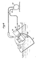
- FIG. 8 represents a third embodiment according to which the drive of the motor and the evacuation of the water is done by a hydraulic system comprising a pump (100), a hydraulic motor (101) whose suction (102) is connected to the discharge (103) of the pump and whose discharge (104) opens inside the basin (2) downstream of the roller.
- the suction (105) of the pump is placed in the lower part of the container (6).
- This device works exactly like the other two and is interesting to use in atmospheres where there is a risk of explosion and where electric motors cannot be used.
- the device according to the invention also has the advantage of being very easily automated. It is possible, for example, to control the inclination of the container (6) to the nature and the thickness of the sheet of hydrocarbon, just as this control can relate to the speed of drive of the drum, that of the propeller and / or the relationship between these two speeds.
- the invention is not limited to the embodiments described. On the contrary, it encompasses all variants.
- any shape for the container (6) for example one can provide rectangular flanges on which would be welded the walls. It is also possible to provide any oleophilic hydrophobic material for the drum, whether this material is present as a constituent of the wall (13) of said drum or as a surface coating of said wall.
Landscapes
- Engineering & Computer Science (AREA)
- General Engineering & Computer Science (AREA)
- Physics & Mathematics (AREA)
- Mechanical Engineering (AREA)
- Civil Engineering (AREA)
- Structural Engineering (AREA)
- Environmental & Geological Engineering (AREA)
- Thermal Sciences (AREA)
- Chemical & Material Sciences (AREA)
- Chemical Kinetics & Catalysis (AREA)
- Removal Of Floating Material (AREA)
- Cleaning By Liquid Or Steam (AREA)
- Treatments Of Macromolecular Shaped Articles (AREA)
- Extraction Or Liquid Replacement (AREA)
- Infusion, Injection, And Reservoir Apparatuses (AREA)
Description
- La présente invention concerne un dispositif permettant la récupération sélective et continue des hydrocarbures présents sous forme de nappe à la surface d'un milieu aqueux.
- La récupération des hydrocarbures à la surface des nappes d'eau, en particulier dans les bassins de décantation naturels ou artificiels nécessite l'utilisation de dispositifs récupérateurs qui peuvent être classés en deux grandes catégories. La première concerne les écrémeurs superficiels qui sont des appareils qui recueillent une certaine couche de liquide en surface, sans faire de distinction entre les hydrocarbures et l'eau. Ils créent un courant superficiel qui permet d'attirer la nappe à distance mais présentent l'inconvénient de fournir un mélange d'eau et d'hydrocarbures. Il est donc nécessaire, pour obtenir une séparation complète, de disposer en aval de ces dispositifs d'un système de séparation alimenté par une pompe dont l'utilisation présente le risque de créer une émulsion du mélange ce qui nécessite soit une autre étape de décantation, soit l'utilisation de dispositifs surdimensionnés permettant de séparer les hydrocarbures présents sous forme d'émulsion dans l'eau. De tels dispositifs sont par exemple connus de l'homme de l'art sous le nom de « goulotte mobile et décrits dans le chapitre 6, Volume : « Liquid Wastes du « Manual on disposai of refinery Wastes », édité par L'american petroleum institute - Copyright 1969.
- La deuxième catégorie de récupérateurs concerne les récupérateurs sélectifs, c'est-à-dire des dispositifs qui mettent en oeuvre les propriétés de certains matériaux qui sont à la fois hydrophobes et oléophiles. De tels matériaux sont par exemple décrits dans la demande de brevet français 2 390 553 « Dispositif d'épuration pour récupérer un composé organique dans un milieu aqueux et leur utilisation est décrite dans le manuel ci-dessus cité qui prévoit un tambour rotatif hydrophobe-oléophile associé à une lame de raclage permettant la récupération des hydrocarbures. On connaît en outre plusieurs réalisations sous forme de disques, bandes sans fin, comme décrites dans les brevets US-A-3 536 199, US-A-3 693 805, US-A-3 992 292 et CA-A-959423. Ces récupérateurs sont donc plus ou moins sélectifs mais leur utilisation présente plusieurs contraintes qui sont pénalisantes pour une exploitation optimale en continu.
- En particulier, il est nécessaire que la nappe d'hydrocarbures soit située à proximité immédiate du rouleau puisque celui-ci ne crée aucun courant superficiel d'attirance.
- En outre, il faut qu'elle soit à son contact pendant un temps suffisamment long puisque l'huile se dépose à la surface du tambour sous la forme d'un film d'épaisseur en général très inférieure à celle de la nappe qui flotte à la surface du milieu aqueux. Ainsi l'utilisation d'un tambour pour récupérer les hydrocarbures d'une nappe en mouvement ne peut se faire qu'avec des équipements compliqués, par exemple comportant plusieurs tambours ou un tambour de grandes dimensions et ne fournit pas un bon rendement. De tels équipements trouvent difficilement leur place dans les installations existantes, en particulier les bassins de décantation des raffineries à moins qu'ils ne soient associés à un équipement de raclage mécanique.
- Au contraire, la présente invention prévoit un dispositif qui permet une récupération sélective et continue d'une nappe d'hydrocarbures présente à la surface d'un milieu aqueux, ce dispositif étant simple et peu encombrant et permettant en outre d'attirer la nappe vers lui.
- Ce dispositif comporte un moyen d'extraction constitué par au moins une paroi continue mise en mouvement par la rotation, autour d'un axe horizontal, d'un moyen d'entraînement, ladite paroi étant constituée, au moins superficiellement, par un matériau oléophile et hydrophobe, et étant agencée de telle sorte que sa partie inférieure puisse être en contact avec les hydrocarbures à récupérer alors que sa partie supérieure est en contact avec un moyen de récupération permettant la récupération des hydrocarbures ayant adhéré sur le moyen d'extraction.
- Selon l'invention, ce dispositif comporte un moyen d'attraction de la nappe, permettant d'attirer cette nappe à proximité immédiate de la partie inférieure de la paroi continue et d'y créer une zone d'accumulation des hydrocarbures dans laquelle ceux-ci sont maintenus à un niveau substantiellement constant. Ce dispositif permet non seulement de récupérer les hydrocarbures avec un très bon rendement puisque ceux-ci sont accumulés au niveau du matériau hydrophobe-oléophile mais encore d'attirer la nappe vers cette zone d'accumulation tout en prévenant tout remélange des hydrocarbures avec l'eau.
- Par matériau hydrophobe et oléophile on entend tout matériau susceptible d'être mouillé, en présence d'eau par les hydrocarbures présents dans la nappe, alors que l'absence de caractère polaire lui évite d'être mouillé par l'eau. De tels matériaux sont bien connus de l'homme de l'art et peuvent consister par exemple en de l'acier inoxydable, de l'acier noir, de l'aluminium ou une matière plastique.
- De préférence, le moyen d'attraction de la nappe est constitué par un récipient qui comporte une première face, plane, parallèle aux génératrices d'un rouleau constituant le moyen d'extraction, et dont le bord supérieur est libre, et une seconde face, reliée à la première par son bord libre. Ces deux faces sont reliées à deux flasques latéraux, parallèles de sorte que l'ensemble définit un volume, ouvert dans sa partie supérieure et enveloppant au moins la partie inférieure du rouleau ; le récipient comporte de plus un moyen de collecte et d'évacuation du milieu aqueux.
- Selon une autre caractéristique, le récipient est mobile en rotation autour d'un axe horizontal entre une position haute et une position basse dans laquelle le bord supérieur de la surface plane est immergé d'une profondeur telle que le débit du fluide entrant dans le récipient est égal à la somme des débits d'extraction des hydrocarbures par le rouleau et d'évacuation de l'eau par le moyen d'évacuation.
- D'une manière préférentielle, le récipient présente une section latérale dissymétrique par rapport au plan passant par l'axe de rotation, de sorte que les parties du récipient situées de part et d'autre de ce plan ont des volumes différents, le volume avant étant le plus petit.
- D'autres caractéristiques et avantages de l'invention apparaîtront à la lecture de la description qui suit, faite d'une manière illustrative et nullement limitative en référence aux dessins annexés sur lesquels :
- la figure 1 est une vue en perspective d'un dispositif réalisé selon l'invention,
- la figure 2 est une vue de face du dispositif de la figure 1,
- la figure 3 est une coupe d'un détail de la figure 2,
- la figure 4 est une vue en coupe selon IV-IV de la figure 2,
- la figure 5 est une vue en coupe selon V-V de la figure 2,
- la figure 6 est une vue partielle, en coupe, d'un second mode de réalisation de l'invention,
- la figure 7 est une vue de dessus du dispositif représenté figure 6
- la figure 8 représente schématiquement un troisième mode de réalisation de l'invention.
- On a représenté sur la figure 1 un dispositif (1) selon l'invention mis en place à une extrémité d'un bassin de décantation (2).
- Le dispositif (1) comporte un bâti (3) posé sur les bords (4) du bassin (2), un rouleau (5), un récipient mobile (6), une lame racleuse (7) dont l'extrémité fixe débouche dans une gouttière (8) de récupération à laquelle est connectée une canalisation souple (9) dont l'extrémité libre débouche dans un bassin de stockage d'hydrocarbures (non représenté). Le dispositif comporte en outre un moteur électrique (10) alimenté par le câble (11), et un moto-réducteur (12) fixé sur le bâti (3).
- La figure 2 représente le dispositif vu de face. Pour des raisons de clarté, on n'a pas représenté le dispositif de raclage comportant la lame racleuse (7) et la gouttière (8).
- Le rouleau (5) comporte une paroi cylindrique (13) et deux faces latérales (14) et (15). La paroi (15) est munie d'un tourillon (16) (figure 3) engagé dans un alésage (17) pratiqué dans un support (18) vissé à la paroi (19) du bâti (3) par les vis (20) et (21). La paroi (15) comporte aussi une roue dentée (22), concentrique au tourillon (16). La paroi (14) est montée de la même manière mais ne comporte pas de roue dentée. Le moto-réducteur (12) est maintenu en place sur le bâti (3) par l'intermédiaire des deux ergots (23) et (24) auxquels il est vissé. A sa partie supérieure est fixé le moteur électrique (10) qui est un moteur triphasé asynchrone de 0, 75KW. Le moto-réducteur (12) est un moto-réducteur du type vis sans fin-roue, dont la vis est située dans l'axe de l'arbre du moteur et tourne à la même vitesse que lui. Elle est prolongée par l'arbre (25). La roue engraine sur la vis et commande l'arbre (26) dont l'extrémité (27) comporte un pignon (28), relié à la roue dentée (22) par une chaîne sans fin (29). Le récipient mobile est constitué par une paroi frontale (30) et située à un niveau inférieur à celui du bâti (4). Il est relié aux montants (32) et (33) du bâti par deux axes (34) et (35).
- L'axe (34) est porté par la paroi latérale (36) du récipient (6) alors que l'axe (35) est porté par la paroi (37) de la goulotte d'évacuation (38) qui est constituée par un tube (39) ouvert à sa partie inférieure (40) et dont l'extrémité supérieure (41) est reliée par un soufflet (42) à un carter (43) entourant-t'arbre (25) et fixé au bâti (4). Le tube (39) est relié à la paroi (51) par un carter cylindrique (60). Le récipient (6) comporte un système de contrepoids (44).
- La figure 4 qui est une vue en coupe du dispositif, représente d'une part, le rouleau (5) le récipient mobile (6) constitué par la paroi frontale (30) qui est plane et prolongée par la paroi arrière (50). Les deux parois sont soudées à la paroi latérale (51). Le bord supérieur (31) est à un niveau inférieur à celui du bord supérieur du flasque (51). Le moyen d'évacuation est constitué par un tube (52), soudé à la partie inférieure du récipient et muni d'une ouverture longitudinale (53), débouchant dans le carter cylindrique (60).
- La lame racleuse (7) est fixée sur le bord (54) de la gouttière (8) par l'intermédiaire d'une charnière (55) et elle est prolongée par une lame (56) biseautée en matériau polymère résistant aux hydrocarbures. La gouttière est percée d'un alésage (57) débouchant dans le tuyau souple (9). Elle est reliée au bâti (4) par un cordon de soudure (58).
- Sur la figure 5, qui est une coupe selon l'axe W de la figure 2, on a représenté le récipient mobile dans ses deux positions extrêmes. Le tube (39) présente une section telle que l'hélice (61), représentée schématiquement par un rectangle, puisse tourner quelle que soit l'orientation du tube, ce qui est rendu possible par le fait que le plan P dans lequel tourne l'hélice contient l'axe de rotation du récipient (6). La section du récipient (6) telle que définie par la paroi frontale (30) et la paroi arrière (50) est dissymétrique par rapport au plan vertical passant par l'axe (90) de rotation du récipient (6) et ainsi qu'on peut le remarquer sur cette figure 5, la partie du récipient située du côté du bord (31) de la paroi frontale (30) a un volume nettement inférieur à celui de la partie située de l'autre côté du plan.
- La partie inférieure de chacun des flasques (51) et (36) présente une échancrure (62) permettant le passage des tourillons (16), (17) quand le récipient (5) est en position basse.
- Les figures 6 et 7 représentent schématiquement une variante de réalisation du dispositif selon l'invention. Sur ces figures, les parties identiques à celles des figures 1 à 5 sont indiquées par les mêmes repères.
- Le récipient (6) comporte des flasques (51), (36) et (37), une paroi avant (30), une paroi arrière (50) qui définissent deux enceintes. L'enceinte (70) enveloppe le rouleau (5) alors que l'enceinte (71) constitue un carter pour l'ensemble constitué par le moteur (10) le moto-réducteur (12), l'arbre (25) et l'hélice (61). Le flasque (51) séparant les deux enceintes comporte à sa partie inférieure une ouverture mettant en communication les deux enceintes. L'enceinte (71) comporte un conduit (72), de diamètre légèrement supérieur à celui de l'hélice. Ce conduit comporte une zone (73) ayant la forme d'une section d'un tore dont l'axe de symétrie est confondu avec l'axe d'articulation (75) du récipient (6). Cet axe (75) est situé au niveau de la goulotte (8) de récupération ; La zone (73) est comprise entre les deux axes concourants (76) et (77).
- Le fonctionnement du dispositif représenté sur la figure 1 est expliqué comme suite en référence en particulier aux figures 1 et 5.
- Le bac (2) est rempli d'eau (77) sur laquelle flotte une nappe (78) d'huile. Le niveau supérieur de la nappe d'huile est représenté par le repère A alors que B représente le niveau inférieur. Quand le dispositif est à l'arrêt, c'est-à-dire que le moteur (10) n'est pas alimenté, la goulotte a la position représentée sur la figure en traits pointillés.
- Quand on met en route le moteur (10), il tourne dans le sens représenté par la flèche (80) et l'hélice (61) évacue l'eau dans la direction de la flèche (61). Le rouleau (5) évacue un débit d'huile dh, la turbine un débit d'eau d.e. Suivant l'inclinaison du récipient et donc la profondeur d'immersion du bord supérieur (31) de la paroi frontale (30) il est introduit dans le récipient (6) un débit d'huile et d'eau, d.i.
- Du fait de la dissymétrie des parties du récipient (5) qui sont de part et d'autre du plan perpendiculaire passant par l'axe de rotation (90), le récipient va prendre une inclinaison selon laquelle le débit d.i. sera égal à la somme dh + d.e.
- Le débit d.e. est choisi sensiblement supérieur au débit dh de sorte que l'on a une accumulation d'hydrocarbures à l'intérieur du récipient.
- On comprend donc aisément que ce dispositif . permet une récupération sélective des hydrocarbures par l'utilisation du tambour et qu'il permet en outre d'attirer les hydrocarbures à proximité de ce tambour sans créer de zone de turbulence ou de déplacement de la nappe ce qui autorise un temps de contact long entre la nappe et le tambour.
- En outre, ce dispositif ne crée aucun remélange ou émulsion des hydrocarbures dans l'eau.
- Il est évident que par action sur les contrepoids (44), sur les vitesses respectives du tambour (5) et, de l'hélice (61) on peut faire varier l'inclinaison du récipient en fonction des caractéristiques des hydrocarbures à récupérer et de l'épaisseur de la nappe. Cependant, on règlera ces différents paramètres de façon à éviter que les hydrocarbures contenus à l'intérieur du récipient ne viennent en contact avec l'hélice et ne soient propulsés vers l'extérieur, ce qui pourrait créer des émulsions et nécessiter une opération de décantation. A cet effet, on peut prévoir de manière classique un détecteur situé à proximité de la goulotte (52) permettant de détecter la présence d'hydrocarbures et actionnant une vanne obturant l'orifice (40) dès détection d'hydrocarbure. Ce détecteur peut agir aussi sur un dispositif permettant le débrayage de l'arbre (25).
- Le dispositif représenté par les figures 6 et 7 fonctionne exactement de la même manière. Sur la figure 6, on voit que la forme du conduit (72) dirige l'eau évacuée dans une direction sensiblement parallèle à la nappe d'hydrocarbures et dans un sens opposé au sens de déplacement, ce qui facilite le déplacement de cette nappe vers l'intérieur de l'enceinte, du fait de la réflexion du courant d'eau sur la paroi du bassin. On a utilisé le dispositif représenté figure 1 pour le déshuilage d'un bassin de décantation rectangulaire de 2 mètres de large sur 10 mètres de long contenant une nappe d'hydrocarbures de 1 cm d'épaisseur. Les hydrocarbures avaient une viscosité de 0, 06 x 10--4 m2/s.. On a utilisé un tambour de 1 m de longueur que l'on a fait tourner à 30 tours par minute. Pour cela, le moteur (10) était un moteur triphasé asynchrone de 0,75KW et 1 400 tr/mn. Le moto-réducteur roue et vis donnait une vitesse de rotation pour la roue égale à 99 tr/mn. Le rapport entre le pignon (27) et la roue (22) était de 1/3 de sorte que le tambour tournait à 30 tours par minute. On a pratiquement déshuilé le bassin en environ 10 mn, ce qui représente un volume d'huile évacué de l'ordre de 200 litres.
- La figure 8 représente un troisième mode de réalisation selon lequel l'entraînement du moteur et l'évacuation de l'eau se fait par un système hydraulique comportant une pompe (100), un moteur hydraulique (101) dont l'aspiration (102) est reliée au refoulement (103) de la pompe et dont l'évacuation (104) débouche à l'intérieur du bassin (2) en aval du rouleau. L'aspiration (105) de la pompe est placée dans la partie basse du récipient (6).
- Ce dispositif fonctionne exactement comme les deux autres et il est intéressant à utiliser dans les atmosphères où il y a des risques de déflagration et où les moteurs électriques ne peuvent être utilisés.
- Le dispositif selon l'invention présente en outre l'avantage d'être très facilement automatisable. On peut par exemple asservir l'inclinaison du récipient (6) à la nature et à l'épaisseur de la nappe d'hydrocarbure de même que cet asservissement peut concerner la vitesse d'entraînement du tambour, celle de l'hélice et/ou le rapport entre ces deux vitesses.
- L'invention n'est pas limitée aux modes de réalisations décrits. Elle englobe au contraire toutes les variantes. En particulier, on peut imaginer toute forme pour le récipient (6), par exemple on peut prévoir des flasques rectangulaires sur lesquels seraient soudées les parois. On peut aussi prévoir tout matériau oléophile hydrophobe pour le tambour, que ce matériau soit présent en tant que constituant de la paroi (13) dudit tambour ou en tant que revêtement de surface de ladite paroi.
Claims (10)
Applications Claiming Priority (2)
| Application Number | Priority Date | Filing Date | Title |
|---|---|---|---|
| FR8210231 | 1982-06-11 | ||
| FR8210231A FR2528412B1 (fr) | 1982-06-11 | 1982-06-11 | Dispositif de recuperation selective et continue des hydrocarbures presents sous forme de nappe a la surface d'un milieu aqueux |
Publications (2)
| Publication Number | Publication Date |
|---|---|
| EP0097082A1 EP0097082A1 (fr) | 1983-12-28 |
| EP0097082B1 true EP0097082B1 (fr) | 1986-09-10 |
Family
ID=9274911
Family Applications (1)
| Application Number | Title | Priority Date | Filing Date |
|---|---|---|---|
| EP83401131A Expired EP0097082B1 (fr) | 1982-06-11 | 1983-06-03 | Dispositif de récupération sélective et continue des hydrocarbures présents sous forme de nappe à la surface d'un milieu aqueux |
Country Status (12)
| Country | Link |
|---|---|
| US (1) | US4681680A (fr) |
| EP (1) | EP0097082B1 (fr) |
| JP (2) | JPS5926187A (fr) |
| BR (1) | BR8303095A (fr) |
| CA (1) | CA1212633A (fr) |
| DE (1) | DE3366033D1 (fr) |
| ES (1) | ES523134A0 (fr) |
| FR (1) | FR2528412B1 (fr) |
| GR (1) | GR78610B (fr) |
| NO (1) | NO159161C (fr) |
| OA (1) | OA07458A (fr) |
| ZA (1) | ZA834268B (fr) |
Families Citing this family (16)
| Publication number | Priority date | Publication date | Assignee | Title |
|---|---|---|---|---|
| US4957636A (en) * | 1989-09-27 | 1990-09-18 | General Technology Applications, Inc. | Device for skimming oil from water |
| US5164083A (en) * | 1990-10-17 | 1992-11-17 | Ahrendt Matthew R | Apparatus for removing oil from a liquid surface |
| DE4109577A1 (de) * | 1991-03-20 | 1992-09-24 | Gutec Umweltschutz | Vorrichtung zur beseitigung von oel |
| US5056956A (en) * | 1991-03-27 | 1991-10-15 | Nicholson Hubert H | Beach protection apparatus |
| US5118412A (en) * | 1991-04-17 | 1992-06-02 | Schmidt Richard J | Fluid recovery apparatus |
| US5200083A (en) * | 1991-10-16 | 1993-04-06 | Jannette Gomez Kaylor | Skimmer and method for its use |
| US5314618A (en) * | 1993-03-29 | 1994-05-24 | Kaylor Timothy R | Oil skimmer |
| US5772871A (en) * | 1996-10-10 | 1998-06-30 | Aircom Manufacturing, Inc. | Coolant reconditioning system |
| US5961825A (en) * | 1997-12-19 | 1999-10-05 | Abasco, Inc. | Coated cylindrical rotary drum for a skimmer apparatus |
| FI3854U1 (fi) * | 1998-11-26 | 1999-03-18 | Lmp Patents Ltd Ab Oy | Laite öljyn tai muun rasvaisen aineen poistamiseksi altaassa olevan nesteen pinnasta |
| US6800195B1 (en) | 2002-06-04 | 2004-10-05 | Thermaco, Inc. | Low cost grease removal system |
| US7208080B2 (en) | 2004-09-16 | 2007-04-24 | Thermaco, Inc. | Low cost oil/grease separator |
| GB2497334B (en) * | 2011-12-08 | 2014-01-08 | James O'neill | Apparatus for treating waste water |
| US9771711B1 (en) | 2014-12-05 | 2017-09-26 | Thermaco, Inc. | Indoor grease trap with multiple plumber fitting possibilities |
| US10960324B1 (en) | 2014-12-11 | 2021-03-30 | Thermaco, Inc. | Low cost oil/grease separator |
| CN105672226A (zh) * | 2016-02-24 | 2016-06-15 | 云南依凡环保工程有限公司 | 一种旋转式水藻分离机 |
Family Cites Families (17)
| Publication number | Priority date | Publication date | Assignee | Title |
|---|---|---|---|---|
| DE1459419A1 (de) * | 1963-08-16 | 1969-01-09 | Otto Justus | Geraet fuer OElabschoepfung von Wasseroberflaechen |
| US3536199A (en) * | 1969-06-27 | 1970-10-27 | Bill G Cornelius | Fire extinguishing oil slick separator |
| US3884807A (en) * | 1970-04-20 | 1975-05-20 | Merlyn W Heddon | Apparatus for skimming in multi-phase fluid media |
| US3693805A (en) * | 1970-04-22 | 1972-09-26 | Fmc Corp | Shrouded drum skimmer |
| US3968041A (en) * | 1971-03-29 | 1976-07-06 | Voss Edwin A De | Apparatus for collecting oil slick from a body of water |
| US3804251A (en) * | 1971-06-10 | 1974-04-16 | Jbf Scient Corp | Floatage collecting apparatus and method |
| US3744257A (en) * | 1971-12-01 | 1973-07-10 | W Spanner | Water-surface cleansing ship |
| CA959423A (en) * | 1972-07-10 | 1974-12-17 | A. Frank Van Dieden | Device for collecting oil from the surface of water |
| JPS49101961A (fr) * | 1973-01-31 | 1974-09-26 | ||
| US3951810A (en) * | 1973-02-06 | 1976-04-20 | Crisafulli Angelo J | Oil skimmer module with free floating weir trough |
| US3992292A (en) * | 1974-10-15 | 1976-11-16 | Marine Construction & Design Co. | Moving belt-type oil skimmer with propulsion induced flow, method and apparatus |
| JPS5284691A (en) * | 1976-01-06 | 1977-07-14 | Takeshi Inoue | Oil recovery boat |
| IT1068189B (it) * | 1976-12-28 | 1985-03-21 | Ravagnan Giancarlo | Impianto per separare er asportare sostanze oleose di liquidi quali acqua. |
| US4115271A (en) * | 1976-09-29 | 1978-09-19 | The Carborundum Company | Rotary drum screen |
| JPS53101170A (en) * | 1977-02-16 | 1978-09-04 | Hisao Tanaka | Oil recovery means |
| FR2390553A1 (fr) * | 1977-05-10 | 1978-12-08 | Anvar | Dispositif d'epuration pour recuperer un compose organique dans un milieu aqueux |
| DE3274664D1 (en) * | 1982-03-01 | 1987-01-22 | Giuseppe Ayroldi | An apparatus for recovering fluid substances floating on a water surface or the like |
-
1982
- 1982-06-11 FR FR8210231A patent/FR2528412B1/fr not_active Expired
-
1983
- 1983-06-03 EP EP83401131A patent/EP0097082B1/fr not_active Expired
- 1983-06-03 DE DE8383401131T patent/DE3366033D1/de not_active Expired
- 1983-06-09 ES ES523134A patent/ES523134A0/es active Granted
- 1983-06-10 ZA ZA834268A patent/ZA834268B/xx unknown
- 1983-06-10 OA OA58025A patent/OA07458A/fr unknown
- 1983-06-10 US US06/503,048 patent/US4681680A/en not_active Expired - Lifetime
- 1983-06-10 GR GR71631A patent/GR78610B/el unknown
- 1983-06-10 BR BR8303095A patent/BR8303095A/pt not_active IP Right Cessation
- 1983-06-10 JP JP58104055A patent/JPS5926187A/ja active Pending
- 1983-06-10 CA CA000430100A patent/CA1212633A/fr not_active Expired
- 1983-06-10 NO NO832127A patent/NO159161C/no not_active IP Right Cessation
-
1992
- 1992-06-10 JP JP1992039581U patent/JPH0746397Y2/ja not_active Expired - Lifetime
Also Published As
| Publication number | Publication date |
|---|---|
| JPH0746397Y2 (ja) | 1995-10-25 |
| FR2528412A1 (fr) | 1983-12-16 |
| ES8403427A1 (es) | 1984-03-16 |
| EP0097082A1 (fr) | 1983-12-28 |
| ZA834268B (en) | 1984-05-30 |
| JPS5926187A (ja) | 1984-02-10 |
| BR8303095A (pt) | 1984-01-31 |
| NO159161B (no) | 1988-08-29 |
| CA1212633A (fr) | 1986-10-14 |
| NO159161C (no) | 1988-12-07 |
| DE3366033D1 (en) | 1986-10-16 |
| GR78610B (fr) | 1984-09-27 |
| JPH0639193U (ja) | 1994-05-24 |
| ES523134A0 (es) | 1984-03-16 |
| NO832127L (no) | 1983-12-12 |
| US4681680A (en) | 1987-07-21 |
| FR2528412B1 (fr) | 1985-12-13 |
| OA07458A (fr) | 1984-12-31 |
Similar Documents
| Publication | Publication Date | Title |
|---|---|---|
| EP0097082A1 (fr) | Dispositif de récupération sélective et continue des hydrocarbures présents sous forme de nappe à la surface d'un milieu aqueux | |
| CA1282346C (fr) | Engin de depollution pour nappes d'eau | |
| EP0608519A2 (fr) | Séparateur centrifuge | |
| FR3042808B1 (fr) | Appareil nettoyeur de piscine a dispositif de franchissement d'obstacle | |
| US3536199A (en) | Fire extinguishing oil slick separator | |
| EP0532397A1 (fr) | Dispositif mélangeur continu, procédé et utilisation dans une installation de pompage d'un fluide de haute viscosité | |
| EP0005411B1 (fr) | Dispositifs et procédés pour récupérer des nappes flottantes de liquide | |
| EP0420751B1 (fr) | Procédé de pompage de mélange liquide gaz dans un puits d'extraction pétrolier et dispositif de mise en oeuvre du procédé | |
| EP2307624B1 (fr) | Chasse pour bachee a ouverture automatique et rapide | |
| US5066407A (en) | Petrochemical recovery machine | |
| EP1123863B1 (fr) | Navire de récupération de produits pétroliers flottants et installation mobile utilisant de tels navires de récupération | |
| US4978448A (en) | System for recovery of floating material from the surface of a body of water | |
| EP0712457A1 (fr) | Dispositif de recuperation de produits polluants repandus sur l'eau ou sur le sol | |
| US5314618A (en) | Oil skimmer | |
| FR2476714A1 (fr) | Appareil de pompage pour liquides pollues | |
| EP0246963B1 (fr) | Récupérateur de pollutions flottantes | |
| WO2003106255A1 (fr) | Appareil d'evacuation de matieres flottantes | |
| FR2693922A1 (fr) | Flottateur cylindrique de séparation des matières en suspension contenues dans un liquide. | |
| FR2487448A1 (fr) | Procede de commande du roulage d'une pompe a boue | |
| KR200324986Y1 (ko) | 부유물 제거 장치 | |
| FR2500932A1 (fr) | Dispositif de controle de circulation de fluide | |
| RU2234570C1 (ru) | Устройство для сбора нефтепродуктов с поверхности воды | |
| FR2567204A1 (fr) | Dispositif elevateur pour liquide pollue en surface par une nappe d'hydrocarbures, et sa mise en oeuvre | |
| CH565905A5 (en) | Collecting oil slick from sea water - uses conduit dragged across water surface and trapping floating oil film | |
| FR2473583A1 (fr) | Nouvel appareil de curage de boue ou de sable comportant un dispositif d'extraction et deux dispositifs de transport perpendiculaires |
Legal Events
| Date | Code | Title | Description |
|---|---|---|---|
| PUAI | Public reference made under article 153(3) epc to a published international application that has entered the european phase |
Free format text: ORIGINAL CODE: 0009012 |
|
| 17P | Request for examination filed |
Effective date: 19830608 |
|
| AK | Designated contracting states |
Designated state(s): BE DE GB IT NL |
|
| GRAA | (expected) grant |
Free format text: ORIGINAL CODE: 0009210 |
|
| AK | Designated contracting states |
Kind code of ref document: B1 Designated state(s): BE DE GB IT NL |
|
| REF | Corresponds to: |
Ref document number: 3366033 Country of ref document: DE Date of ref document: 19861016 |
|
| ITF | It: translation for a ep patent filed | ||
| PLBE | No opposition filed within time limit |
Free format text: ORIGINAL CODE: 0009261 |
|
| STAA | Information on the status of an ep patent application or granted ep patent |
Free format text: STATUS: NO OPPOSITION FILED WITHIN TIME LIMIT |
|
| 26N | No opposition filed | ||
| ITTA | It: last paid annual fee | ||
| PGFP | Annual fee paid to national office [announced via postgrant information from national office to epo] |
Ref country code: GB Payment date: 19990528 Year of fee payment: 17 |
|
| PGFP | Annual fee paid to national office [announced via postgrant information from national office to epo] |
Ref country code: NL Payment date: 19990531 Year of fee payment: 17 |
|
| PGFP | Annual fee paid to national office [announced via postgrant information from national office to epo] |
Ref country code: DE Payment date: 19990602 Year of fee payment: 17 |
|
| PGFP | Annual fee paid to national office [announced via postgrant information from national office to epo] |
Ref country code: BE Payment date: 19990624 Year of fee payment: 17 |
|
| PG25 | Lapsed in a contracting state [announced via postgrant information from national office to epo] |
Ref country code: GB Free format text: LAPSE BECAUSE OF NON-PAYMENT OF DUE FEES Effective date: 20000603 |
|
| PG25 | Lapsed in a contracting state [announced via postgrant information from national office to epo] |
Ref country code: BE Free format text: LAPSE BECAUSE OF NON-PAYMENT OF DUE FEES Effective date: 20000630 |
|
| BERE | Be: lapsed |
Owner name: ELF FRANCE Effective date: 20000630 |
|
| PG25 | Lapsed in a contracting state [announced via postgrant information from national office to epo] |
Ref country code: NL Free format text: LAPSE BECAUSE OF NON-PAYMENT OF DUE FEES Effective date: 20010101 |
|
| GBPC | Gb: european patent ceased through non-payment of renewal fee |
Effective date: 20000603 |
|
| NLV4 | Nl: lapsed or anulled due to non-payment of the annual fee |
Effective date: 20010101 |
|
| PG25 | Lapsed in a contracting state [announced via postgrant information from national office to epo] |
Ref country code: DE Free format text: LAPSE BECAUSE OF NON-PAYMENT OF DUE FEES Effective date: 20010403 |