EP0096763A2 - Safety helmet and method of manufacturing this helmet - Google Patents
Safety helmet and method of manufacturing this helmet Download PDFInfo
- Publication number
- EP0096763A2 EP0096763A2 EP83105042A EP83105042A EP0096763A2 EP 0096763 A2 EP0096763 A2 EP 0096763A2 EP 83105042 A EP83105042 A EP 83105042A EP 83105042 A EP83105042 A EP 83105042A EP 0096763 A2 EP0096763 A2 EP 0096763A2
- Authority
- EP
- European Patent Office
- Prior art keywords
- helmet
- shells
- shell
- protective helmet
- die
- Prior art date
- Legal status (The legal status is an assumption and is not a legal conclusion. Google has not performed a legal analysis and makes no representation as to the accuracy of the status listed.)
- Withdrawn
Links
Images

Classifications
-
- A—HUMAN NECESSITIES
- A42—HEADWEAR
- A42B—HATS; HEAD COVERINGS
- A42B3/00—Helmets; Helmet covers ; Other protective head coverings
- A42B3/04—Parts, details or accessories of helmets
- A42B3/06—Impact-absorbing shells, e.g. of crash helmets
- A42B3/062—Impact-absorbing shells, e.g. of crash helmets with reinforcing means
- A42B3/063—Impact-absorbing shells, e.g. of crash helmets with reinforcing means using layered structures
- A42B3/064—Impact-absorbing shells, e.g. of crash helmets with reinforcing means using layered structures with relative movement between layers
-
- A—HUMAN NECESSITIES
- A42—HEADWEAR
- A42C—MANUFACTURING OR TRIMMING HEAD COVERINGS, e.g. HATS
- A42C2/00—Manufacturing helmets by processes not otherwise provided for
-
- B—PERFORMING OPERATIONS; TRANSPORTING
- B29—WORKING OF PLASTICS; WORKING OF SUBSTANCES IN A PLASTIC STATE IN GENERAL
- B29C—SHAPING OR JOINING OF PLASTICS; SHAPING OF MATERIAL IN A PLASTIC STATE, NOT OTHERWISE PROVIDED FOR; AFTER-TREATMENT OF THE SHAPED PRODUCTS, e.g. REPAIRING
- B29C70/00—Shaping composites, i.e. plastics material comprising reinforcements, fillers or preformed parts, e.g. inserts
- B29C70/04—Shaping composites, i.e. plastics material comprising reinforcements, fillers or preformed parts, e.g. inserts comprising reinforcements only, e.g. self-reinforcing plastics
- B29C70/28—Shaping operations therefor
Definitions
- the present invention relates to a protective helmet according to the preamble of claim 1.
- a protective helmet with an outer shell and with an inner shell spaced from the outer shell and with foam bodies which are arranged between the shells is already known from US Pat. No. 4,069,565.
- the inner shell is made of a flowable plastic so that it can adapt to the shape of the helmet wearer's head.
- the foam layer arranged between the shells serves as an energy-absorbing layer, which deforms when an impact hits the outer shell and thus absorbs energy.
- the strength and torsional stiffness of such a helmet is determined exclusively by the properties of the outer helmet shell.
- a force acts orthogonally on the outer helmet shell
- this force causes a deflection of the outer helmet shell, which leads to a compressive stress running tangentially in this helmet shell, which builds up the reaction force to the attacking force.
- a certain amount of energy is absorbed by the deforming foam layer when the external force begins to attack, and thus when the outer helmet shell begins to bend, the foam layer only contributes to the build-up of an additional reaction force during the deformation process, but not during a quasi-static deformation state of the outer helmet shell . Therefore, in the final deformation stage, the entire acting force has to be absorbed by compressive stresses in the outer helmet shell, which build up the reaction force.
- the outer helmet shell must be the same Stei in such a protective helmet have the ability that a single-shell helmet with inner padding should have. So the designer of such a helmet has only two alternatives: he builds a high-strength, connection-rigid helmet that has a large outer wall thickness and thus a high weight, or he builds a light, comfortable helmet that is injured of the neck muscles due to its low weight or the spine of the protective helmet wearer avoids and accepts a low helmet strength and a low torsional rigidity of the helmet.
- a protective helmet with an inner shell and an outer shell is known from DE-AS 24 04 849. Between the inner shell and outer shell there is an energy-absorbing layer attached to the inner surface of the helmet shell, which preferably consists of hard foam. This layer also has projections made of this rigid foam, which are tubular and extend from the outer helmet shell to the inner helmet shell.
- the energy-absorbing layer of this protective helmet which consists of hard foam, differs from the energy-absorbing layer according to US Pat. No. 4,069,565 only in that the layer in the helmet according to DE-AS is not homogeneous, but is provided with cavities. The operation of the helmet is the same, so that this helmet also has the disadvantages with which the helmet according to US Pat. No. 4,069,565 is afflicted.
- a helmet with an outer shell and an inner shell is known, in which an energy-absorbing layer, which consists of a honeycomb material, is provided between the shells.
- an energy-absorbing layer which consists of a honeycomb material.
- a quasi-static pressure force which acts on the outer helmet shell, must be absorbed entirely by tangential compressive stresses in the outer helmet shell, which cause a reaction force corresponding to the pressure force.
- the outer shell must already be used with this helmet alone have such a torsion and pressure resistance, as they have the entire helmet so h.
- This helmet also has the disadvantages inherent in the helmet according to US Pat. No. 4,064,565.
- a single-shell helmet which has a soft inner padding and a soft outer padding.
- the padding is formed by an airtight layer that envelops the inside and outside of the helmet shell and is connected to the inside and outside at several points and is filled with compressed air.
- This helmet is intended to help prevent injuries to the opponent of the helmet wearer from a hard shell in martial arts.
- This helmet only has the protective function in common with the protective helmet according to the invention.
- the invention is based on the technical problem of creating a helmet according to the preamble of the main claim, which has a high pressure and torsional strength with low weight.
- the inner helmet shell merges into the outer shell of the helmet via connecting elements which are integrally connected to the two shells.
- the cavities between the inner shell and outer shell outside the connecting elements are filled with hard foam or foam body.
- each element of the outer shell of the helmet is connected to each element of the inner shell of the helmet in such a way that both a tangential displacement of the shell elements relative to one another and an orthogonal displacement are largely prevented within a load range predetermined by the strength of the connecting elements.
- this compressive force will deform the entire framework-like structure, consisting of the outer shell, inner shell, connecting elements and foam body.
- compressive stresses occur in the outer shell, while tensile stresses are absorbed in the inner shell.
- Approximately in the middle between the two shells is a neutral zone, in which neither compressive nor tensile stresses occur.
- a helmet designed according to claim 2 has a special one high strength and breaking strength.
- the construction of the protective helmet according to the features of claim 3 enables the shell connection with elements that are adapted to the size of the load occurring.
- the protective helmet Due to the arrangement of the connecting strips according to claim 4, the protective helmet has a closed shape and high strength at its edges.
- the arrangement of the connecting webs described in claim 6 contributes to a uniform distribution of the load occurring on the respective shells.
- the connecting bars ensure that the distance between the innermost shell and the outer shell, which is necessary for helmet strength, is ensured even when the outer shell is subjected to punctiform loads. If the outer shell is subjected to extreme loads, the outer shell is first pressed in, the connecting webs and the foam bodies being destroyed and pressed together. The energy absorbed thereby reduces the impact energy transmitted to the innermost shell.
- the protective helmet according to claim 7 is particularly easy to manufacture.
- the method according to claim 8 for the manufacture of protective helmets enables a one-piece construction of the multi-shell protective helmet, ensures the exact adherence to the desired wall thickness of the outer shell and the inner shells and enables a simple and quick Fer safety helmets.
- the method according to claim 9 ensures a high-gloss and smooth helmet surface and facilitates the insertion of the first nonwoven or fabric cut, since the gel coat acts like an adhesive applied to the inner surface of the die.
- a glass fiber reinforcement of the polymer is also obtained in the area of the reinforcing elements, since e.g. embeds a relatively thick and soft nonwoven fabric in all cavities left free by the foam body before the injection.
- connecting webs and connecting strips can be produced in a particularly advantageous manner by a method according to the features of claim 12.
- the protective helmet has an outer shell 1 and an inner shell 2 made of glass fiber reinforced polymer.
- the shells 1, 2 are firmly connected to one another via connecting elements 5, 6 made of glass fiber reinforced polymer.
- the connecting elements 5, 6 consist of connecting webs 5, which are each perpendicular to the inside of the outer shell and the outside of the inner shell, and connecting strips 6, which connect the shells 1, 2 together along a helmet opening and along a visor opening. Further connecting strips 6 run in a beam-like manner starting from an upper area of the protective helmet up to the helmet opening.
- the cavity lying between the shells, which is not filled by connecting strips 6 and connecting struts 5, contains foam bodies 3 made of a rigid foam.
- the outer shell 1 contains a first nonwoven blank
- the inner shell 2 contains a second nonwoven blank.
- the respective non-woven fabrics each extend so far into the connecting struts and connecting strips that they touch each other.
- the surface of the outer shell 1 is covered with a gel coat layer 4.
- the inner padding is covered with a cloth.
- thermoset instead of the glass fiber reinforced polymer, any other thermoset can be used. It is also possible to manufacture the shells and the connecting elements from a thermoplastic.
- a layer of gel coat 4 is injected into a die 9, the inner shape of which corresponds to the outer shape of the outer shell 1.
- the gel coat 4 gives a smooth and hard surface of the outer shell 1.
- a soft, about 2 cm thick, first fiber fleece blank 7 made of glass fiber material is inserted into the still wet gel coat so that it covers the entire inner surface of the matrix 9 provided with the gel coat 4 becomes.
- a plurality of foam bodies 3 or a one-piece foam body 3 are inserted into the die 9 designed with fiber fleece blank 7.
- the foam bodies 3 have cylindrical bores, through which the shape of the connecting webs 5 is predetermined, and each have an intermediate space with the adjacent foam body 3, which defines the shape of the connecting strips 6.
- a second nonwoven blank 8 made of glass fiber material is placed on the foam body 3. This second blank also has a thickness of approximately 2 cm and a structure similar to cotton wool.
- a male 10 consists of a core 11, a plurality of molded parts 12 and a jacket 13 made of silicone rubber and approximately 4 mm thick.
- the jacket is designed such that it surrounds the molded parts 12 surrounding the core 11 with slight pressure.
- the male part 10 is introduced by first the jacket is inserted into the channel formed by the second fiber flow layer 8 trough 13, then the moldings are inserted into the casing 13 12, in which the core 11 by means of a guide device is retracted.
- the shape of the inner surface of the inner shell 2 is determined by the outer surface of the jacket 13.
- Polymer is injected through an injection opening i4 provided on the die 9 in the area of the subsequent visor opening of the protective helmet.
- the injection process is carried out relatively slowly in order to allow air bubbles to escape from the space formed by the male part 10 and the female part 9.
- the die 9 can be heated in order to liquefy the polymer.
- the die 9 can be cooled in order to derive the heat released from the exothermic reaction of the curing polymer.
- the male part 10 is removed and the protective helmet is removed from the female part 9. Now the visor opening is cut out of the helmet.
- a visor and a chin strap are attached to the helmet and the helmet is lined with an inner padding.
- the protective helmet can consist of an outer shell with a plurality of inner shells spaced apart from one another and from the outer shell.
Abstract
Description
Die vorliegende Erfindung bezieht sich auf einen Schutzhelm nach dem Oberbegriff des Anspruchs 1.The present invention relates to a protective helmet according to the preamble of
Aus der US-PS 40 69 565 ist bereits ein Schutzhelm mit einer Außenschale und mit einer von der Außenschale beabstandeten Innenschale und mit Schaumstoffkörpern, die zwischen den Schalen angeordnet sind, bekannt. Die innere Schale besteht aus einem fließfähigen Kunststoff, um sich der Kopfform des Schutzhelmträgers anpassen zu können. Die zwischen den Schalen angeordnete Schaumstoffschicht dient als energieabsorbierende Schicht, die sich bei einem auf die Außenschale auftreffenden Stoß verformt und damit Energie absorbiert. Die Festigkeit und Verwindungsstreifigkeit eines derartigen Helmes wird ausschließlich durch die Eigenschaften der äußeren Helmschale bestimmt. Wirkt beispielsweise eine orthogonal auf die äußere Helmschale gerichtete Kraft auf den Helm ein, so bewirkt diese Kraft eine Durchbiegung der äußeren Helmschale, die zu einer tangential in dieser Helmschale verlaufenden Druckspannung führt, welche die Reaktionskraft zu der angreifenden Kraft aufbaut. Zwar wird bei beginnendem Angreifen der äußeren Kraft und damit bei beginnender Durchbiegung der äußeren Helmschale durch die sich verformende Schaumstoffschicht eine gewisse Energie aufgenommen, jedoch trägt die Schaumstoffschicht nur während des Verformungsvorganges, nicht jedoch während eines quasistatischen Verformungszustandes der äußeren Helmschale zum Aufbau einer zusätzlichen Reaktionskraft bei. Daher muß im Verformungsendstadium die gesamte einwirkende Kraft durch Druckspannungen in der äußeren Helmschale, die die Reaktionskraft aufbauen, aufgenommen werden. Daher muß bei einem derartigen Schutzhelm die äußere Helmschale die gleiche Steifigkeit aufweisen, wie sie ein einschaliger Helm mit Innenpolsterung haben müßte. Damit hat der Konstrukteur eines derartigen Helmes lediglich zwei Alternativen: Er baut einen hochfesten, verbindungssteifen Helm, der eine große Außenwandstärke und damit ein hohes Eigengewicht aufweist, oder er baut einen leichten, angenehm zu tragenden Helm, der aufgrund seines niedrigen Eigengewichtes eine Verletzung der Nackenmuskulatur bzw. der Wirbelsäule des Schutzhelmträgers vermeidet und nimmt dabei eine niedrige Helmfestigkeit und eine niedrige Verwindungssteifigkeit des Helmes in Kauf.A protective helmet with an outer shell and with an inner shell spaced from the outer shell and with foam bodies which are arranged between the shells is already known from US Pat. No. 4,069,565. The inner shell is made of a flowable plastic so that it can adapt to the shape of the helmet wearer's head. The foam layer arranged between the shells serves as an energy-absorbing layer, which deforms when an impact hits the outer shell and thus absorbs energy. The strength and torsional stiffness of such a helmet is determined exclusively by the properties of the outer helmet shell. If, for example, a force acts orthogonally on the outer helmet shell, this force causes a deflection of the outer helmet shell, which leads to a compressive stress running tangentially in this helmet shell, which builds up the reaction force to the attacking force. Although a certain amount of energy is absorbed by the deforming foam layer when the external force begins to attack, and thus when the outer helmet shell begins to bend, the foam layer only contributes to the build-up of an additional reaction force during the deformation process, but not during a quasi-static deformation state of the outer helmet shell . Therefore, in the final deformation stage, the entire acting force has to be absorbed by compressive stresses in the outer helmet shell, which build up the reaction force. Therefore, the outer helmet shell must be the same Stei in such a protective helmet have the ability that a single-shell helmet with inner padding should have. So the designer of such a helmet has only two alternatives: he builds a high-strength, connection-rigid helmet that has a large outer wall thickness and thus a high weight, or he builds a light, comfortable helmet that is injured of the neck muscles due to its low weight or the spine of the protective helmet wearer avoids and accepts a low helmet strength and a low torsional rigidity of the helmet.
Aus der DE-AS 24 04 849 ist ein Schutzhelm mit einer Innenschale und einer Außenschale bekannt. Zwischen Innenschale und Außenschale liegt eine an der Innenfläche der Helmschale befestigte energieabsorbierende Schicht, die vorzugsweise aus Hartschaum besteht. Diese Schicht weist ebenfalls aus diesem Hartschaum bestehende Vorsprünge auf, die röhrenförmig ausgebildet sind und sich von der äußeren Helmschale bis zur inneren Helmschale erstrecken. Die energieabsorbierende Schicht dieses Schutzhelmes, die aus Hartschaum besteht, unterscheidet sich von der energieabsorbierenden Schicht nach der US-PS 40 69 565 lediglich dadurch, daß die Schicht bei dem Helm nach der DE-AS nicht homogen, sondern mit Hohlräumen versehen ist. Die Wirkungsweise des Helmes ist gleich, so daß auch dieser Helm die Nachteile hat, mit der der Helm nach der US-PS 40 69 565 behaftet ist.A protective helmet with an inner shell and an outer shell is known from DE-AS 24 04 849. Between the inner shell and outer shell there is an energy-absorbing layer attached to the inner surface of the helmet shell, which preferably consists of hard foam. This layer also has projections made of this rigid foam, which are tubular and extend from the outer helmet shell to the inner helmet shell. The energy-absorbing layer of this protective helmet, which consists of hard foam, differs from the energy-absorbing layer according to US Pat. No. 4,069,565 only in that the layer in the helmet according to DE-AS is not homogeneous, but is provided with cavities. The operation of the helmet is the same, so that this helmet also has the disadvantages with which the helmet according to US Pat. No. 4,069,565 is afflicted.
Aus der FR-PS 23 46 292 ist ein Helm mit einer Außenschale und einer Innenschale bekannt, bei dem zwischen den Schalen eine energieabsorbierende Schicht, die aus einem wabenförmigen Material besteht, vorgesehen ist. Auch bei diesem Helm muß eine quasistatische Druckkraft, die auf die äußere Helmschale einwirkt, völlig durch tangentiale Druckspannungen in der äußeren Helmschale aufgenommen werden, die eine der Druckkraft entsprechende Reaktionskraft hervorrufen. Demgemäß muß auch bei diesem Helm allein die Außenschale bereits eine derartige Verwindungs- und Druckfestigkeit aufweisen, wie sie der gesamte Helm haben so h. Damit hat auch dieser Helm die Nachteile, die dem Helm nach der US-PS 40 64 565 zueigen sind.From FR-PS 23 46 292 a helmet with an outer shell and an inner shell is known, in which an energy-absorbing layer, which consists of a honeycomb material, is provided between the shells. With this helmet too, a quasi-static pressure force, which acts on the outer helmet shell, must be absorbed entirely by tangential compressive stresses in the outer helmet shell, which cause a reaction force corresponding to the pressure force. Accordingly, the outer shell must already be used with this helmet alone have such a torsion and pressure resistance, as they have the entire helmet so h. This helmet also has the disadvantages inherent in the helmet according to US Pat. No. 4,064,565.
Aus der US-PS 39 99 220 ist ein einschaliger Helm bekannt, der eine weiche Innenpolsterung und eine weiche Außenpolsterung hat. Die Polsterung wird durch eine luftdichte Schicht, die die Helmschale innen und außen umhüllt und mit dieser sowohl innen als auch außen an mehreren Punkten verbunden ist, und mit Druckluft gefüllt ist, gebildet. Dieser Helm soll dazu beitragen, bei Kampfsportarten die Verletzung des Gegners des Helmträgers durch eine harte Helmschale zu verhindern. Mit dem erfindungsgemäßen Schutzhelm hat dieser Helm lediglich die Schutzfunktion gemeinsam.From US-PS 39 99 220 a single-shell helmet is known which has a soft inner padding and a soft outer padding. The padding is formed by an airtight layer that envelops the inside and outside of the helmet shell and is connected to the inside and outside at several points and is filled with compressed air. This helmet is intended to help prevent injuries to the opponent of the helmet wearer from a hard shell in martial arts. This helmet only has the protective function in common with the protective helmet according to the invention.
Der Erfindung liegt das technische Problem zugrunde, einen Helm nach dem Oberbegriff des Hauptanspruchs zu schaffen, der bei niedrigem Gewicht eine hohe Druck- und Verwindungsfestigkeit hat.The invention is based on the technical problem of creating a helmet according to the preamble of the main claim, which has a high pressure and torsional strength with low weight.
Dieses technische Problem wird bei einem Schutzhelm nach dem Oberbegriff des Hauptanspruchs durch das Merkmal des kennzeichnenden Teils des Hauptanspruchs gelöst.This technical problem is solved in a protective helmet according to the preamble of the main claim by the feature of the characterizing part of the main claim.
Bei dem erfindungsgemäßen Helm geht die Helminnenschale in die Helmaußenschale über einstückig mit beiden Schalen verbundene Verbindungselemente über. Die zwischen Helminnenschale und Helmaußenschale außerhalb der Verbindungselemente liegenden Hohlräume sind durch Hartschaum bzw. Schaumstoffkörper ausgefüllt. Hierdurch ergibt sich erfindungsgemäß eine Art Fachwerkstruktur, bei der je ein Element der Helmaußenschale über mit diesem einstückige Verbindungselemente mit einem Element der Helminnenschale verbunden ist. Der zwischen dem Helmaußenschalenelement und dem darunter liegenden Innenschalenelement eingeschlossene Hohlraum, der durch Verbindungselemente festgelegt ist, ist also durch ein Schaumstoffelement ausgefüllt. Damit ist jedes Element der Helmaußenschale mit jedem Element der Helminnenschale so verbunden, daß innerhalb eines durch die Stärke der Verbindungselemente vorgegebenen Belastungsbereiches sowohl eine Tangentialverschiebung der Schalenelemente gegeneinander wie auch eine orthogonale Verschiebung weitgehend verhindert wird. Wirkt nun eine in etwa punktförmige Druckkraft auf den Helm ein, so wird durch diese Druckkraft die gesamte fachwerkähnliche Struktur, bestehend aus Außenschale, Innenschale, Verbindungselemente und Schaumstoffkörper, verformt werden. Hierbei treten in der Außenschale Druckspannungen auf, während in der Innenschale Zugspannungen aufgenommen werden. Etwa in der Mitte zwischen den beiden Schalen befindet sich eine neutrale Zone, in der weder Druck- noch Zugspannungen auftreten. Die gesamte Belastung wird also sowohl durch die Außenschale wie auch durch die Innenschale aufgenommen, so daß die Zugfestigkeit der Innenschale die Druckfestigkeit der Außenschale erhöht. Aufgrund dieser erfindungsgemäßen Aufteilung der Helmbelastung auf beide Helmschalen wird eine vielfache Festigkeit gegenüber einer Helmkonstruktion erreicht, die die gleiche Innen- und Außenschale und die gleichen Schaumstoffkörper wie der Anmeldungsgegenstand hat, bei der jedoch aufgrund fehlender einstückiger Verbindungselemente eine relative Tangentialverschiebung von Innenschalenelementen gegenüber Außenschalenelementen möglich ist. Aufgrund der enormen Verwindungssteifigkeit, die durch die erfindungsgemäße Helmstruktur erreicht wird, ist es möglich, den Helm mit geringeren Materialstärken auszuführen, als sie z.B. ein Helm gemäß der US-PS 40 64 565 hat. Dies führt zu einer erheblichen Gewichtseinsparung und damit zu einer niedrigeren Belastung der Halswirbelsäule und der Nackenmuskulatur eines Helmtärgers im Falle eines Sturzes.In the helmet according to the invention, the inner helmet shell merges into the outer shell of the helmet via connecting elements which are integrally connected to the two shells. The cavities between the inner shell and outer shell outside the connecting elements are filled with hard foam or foam body. This results, according to the invention, in a type of truss structure in which one element of the outer shell of the helmet is connected to one element of the inner shell of the helmet by means of connecting elements integral therewith. The enclosed between the outer shell shell element and the underlying inner shell element cavity, which is fixed by connecting elements is filled with a foam element. Thus, each element of the outer shell of the helmet is connected to each element of the inner shell of the helmet in such a way that both a tangential displacement of the shell elements relative to one another and an orthogonal displacement are largely prevented within a load range predetermined by the strength of the connecting elements. If an approximately punctiform compressive force acts on the helmet, this compressive force will deform the entire framework-like structure, consisting of the outer shell, inner shell, connecting elements and foam body. Here compressive stresses occur in the outer shell, while tensile stresses are absorbed in the inner shell. Approximately in the middle between the two shells is a neutral zone, in which neither compressive nor tensile stresses occur. The entire load is thus absorbed by both the outer shell and the inner shell, so that the tensile strength of the inner shell increases the compressive strength of the outer shell. Due to this division of the helmet load according to the invention on both helmet shells, a multiple strength is achieved compared to a helmet construction which has the same inner and outer shell and the same foam body as the subject of the application, but in which a relative tangential displacement of inner shell elements compared to outer shell elements is possible due to the lack of one-piece connecting elements . Due to the enormous torsional rigidity that is achieved by the helmet structure according to the invention, it is possible to design the helmet with lower material thicknesses than, for example, a helmet according to US Pat. No. 4,064,565. This leads to considerable weight savings and thus to less stress on the cervical spine and neck muscles of a helmet wearer in the event of a fall.
Ein nach Anspruch 2 ausgebildeter Helm hat eine besonders hohe Steigkeit und Bruchfestigkeit.A helmet designed according to
Die Bauweise des Schutzhelms nach den Merkmalen des Anspruchs 3 ermöglicht die Schalenverbindung mit Elementen, die der Größe der auftretenden Belastung angepaßt sind.The construction of the protective helmet according to the features of
Durch die Anordnung der Verbindungsstreifen nach Anspruch 4 hat der Schutzhelm an seinen Kanten eine geschlossene Form und eine hohe Festigkeit.Due to the arrangement of the connecting strips according to
Durch die gewölbeartige bzw. strahlenartige Anordnung der Verbindungsstreifen nach Anspruch 5 werden bei einer Belastung auftretende Druck- und Zugkräfte gleichmäßig über die Außenschale und die Innenschalen verteilt. Die zusätzliche Verstärkung des Schutzhelms im Bereich von Befestigungspunkten des Visiers und des Kinnriemens leitet auftretende Kräfte über eine große Fläche in die Schalen ein.Due to the arch-like or radiation-like arrangement of the connecting strips according to
Die in Anspruch 6 beschriebene Anordnung der Verbindungsstege trägt zu einer gleichmäßigen Verteilung auftretender Belastung an den jeweiligen Schalen bei. Durch die Verbindungsstege ist die für die Helmfestigkeit nötige Entfernung zwischen der innersten Schale und Außenschale auch bei punktförmiger Belastung der Außenschale gesichert. Bei einer extremen Belastung der Außenschale wird zunächst die Außenschale eingedrückt, wobei die Verbindungsstege und die Schaumstoffkörper zerstört und zusammengedrückt werden. Die hierdurch absorbierte Energie reduziert die an die innerste Schale übertragene Aufprallenergie.The arrangement of the connecting webs described in
Der Schutzhelm nach Anspruch 7 ist besonders einfach herzustellen. Das Verfahren nach Anspruch 8 zum Herstellen von Schutzhelmen ermöglicht eine einstückige Bauweise des mehrschaligen Schutzhelms, sichert die genaue Einhaltung der gewünschten Wandstärke der Außenschale und der Innenschalen und ermöglicht eine einfache und schnelle Fertigung der Schutzhelme.The protective helmet according to
Das Verfahren nach Anspruch 9 sichert eine hochglänzende und glatte Helmoberfläche und erleichtert das Einlegen des ersten Faservlies- oder Gewebezuschnitts, da das Gelcoat wie ein auf die Innenfläche der Matrize aufgebrachter Klebstoff wirkt.The method according to
Verfährt man nach den Merkmalen des Anspruchs 10, indem man die Injektionsnase vorzugsweise in einem später herauszuschneidenden Visierausschnitt des Helmes legt, so erhält man einen optisch ansprechenden Helm.If one proceeds according to the features of
Durch Anwendung der Merkmale des Anspruchs 11 erhält man eine Glasfaserverstärkung des Polymerisats auch im Bereich der Verstärkungselemente, da sich z.B. ein relativ dickes und weiches Faservlies vor der Injektion in alle durch die Schaumstoffkörper freigelassenen Hohlräume einbettet.By applying the features of
In besonders vorteilhafter Weise lassen sich die Verbindungsstege und Verbindungsstreifen durch ein Verfahren nach den Merkmalen des Anspruchs 12 herstellen.The connecting webs and connecting strips can be produced in a particularly advantageous manner by a method according to the features of
Anhand eines in der Zeichnung dargestellten Ausführungsbeispieles eines Schutzhelms und einer Vorrichtung zum Durchführen des angegebenen Verfahrens wird die Erfindung nachfolgend näher beschrieben.The invention is described in more detail below on the basis of an exemplary embodiment of a protective helmet and a device for carrying out the method shown in the drawing.
Es zeigen:
Figur 1 eine perspektivische Darstellung eines zweischaligen Schutzhelms ohne Außenschale,Figur 2 einen Querschnitt durch den Schutzhelm von Fig. 1,Figur 3 einen Längsschnitt durch den Schutzhelm von Fig. 1,Figur 4 eine vergrößerte Teildarstellung eines Ausschnitts vonFigur 3, undFigur 5 einen Querschnitt durch eine Vorrichtung zum Her- stellen des Schutzhelms.
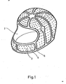
- FIG. 1 shows a perspective illustration of a double-shell protective helmet without an outer shell,
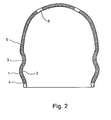
- FIG. 2 shows a cross section through the protective helmet from FIG. 1,
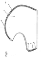
- FIG. 3 shows a longitudinal section through the protective helmet from FIG. 1,
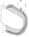
- Figure 4 is an enlarged partial view of a section of Figure 3, and
- 5 shows a cross section through an apparatus for Her - provide the protective helmet.
Der Schutzhelm hat eine Außenschale 1 und eine Innenschale 2 aus glasfaserverstärktem Polymerisat. Die Schalen 1, 2 sind über Verbindungselemente 5, 6 aus glasfaserverstärktem Polymerisat fest miteinander verbunden. Die Verbindungselemente 5, 6 bestehen aus Verbindungsstegen 5, die jeweils senkrecht auf der Innenseite der Außenschale und der Außenseite der Innenschale stehen, und Verbindungsstreifen 6, die die Schalen 1, 2 entlang einer Helmöffnung und entlang einer Visieröffnung miteinander verbinden. Weitere Verbindungsstreifen 6 laufen strahlenartig von einem oberen Bereich des Schutzhelmes ausgehend bis zu der Helmöffnung. Der zwischen den Schalen liegende Hohlraum, der nicht durch Verbindungsstreifen 6 und Verbindungsstrege 5 ausgefüllt ist, beinhaltet Schaumstoffkörper 3 aus einem Hartschaum. Die Außenschale 1 beinhaltet einen ersten Faservlieszuschnitt, die Innenschale 2 beinhaltet einen zweiten Faservlieszuschnitt. Die jeweiligen Faservliese erstrecken sich jeweils soweit in die Verbindungsstrege und Verbindungsstreifen, daß sie sich gegenseitig berühren. Die Oberfläche der Außenschale 1 ist mit einer Gelcoat-Schicht 4 bedeckt. Auf die Innenseite der Innenschale 2 ist eine aus Schaumgummi bestehende Innenpolsterung aufgeklebt. Die Innenpolsterung ist mit einem Tuch überzogen.The protective helmet has an
Anstelle des glasfaserverstärkten Polymerisates kann auch jedes andere Duroplast verwendet werden. Ebenfall ist es möglich, die Schalen sowie die Verbindungselemente aus einem thermoplastischen Kunststoff herzustellen.Instead of the glass fiber reinforced polymer, any other thermoset can be used. It is also possible to manufacture the shells and the connecting elements from a thermoplastic.
Im Folgenden wird das Verfahren zum Herstellen eines zweischaligen Schutzhelmes im einzelnen beschrieben.The process for producing a double-shell protective helmet is described in detail below.
In eine Matrize 9, deren Innenform der Außenform der Außenschale 1 entspricht, wird eine Schicht aus Gelcoat 4 eingespritzt. Durch das Gelcoat4 erhält man eine glatte und harte Oberfläche der Außenschale 1. In das noch feuchte Gelcoat wird ein watteartig weicher, etwa 2 cm dicker, erster Faservlieszuschnitt 7 aus Glasfasermaterial eingelegt, so daß durch ihn die gesamte Innenoberfläche der mitGelcoat 4 versehenen Matrize 9 bedeckt wird. In die mit Faservlieszuschnitt 7 ausgelegte Matrize 9 werden mehrere Schaumstoffkörper 3 oder ein einstückiger Schaumstoffkörper 3 eingelegt. Die Schaumstoffkörper 3 haben zylindrische Bohrungen, durch die die Form der Verbindungsstege 5 vorbestimmt wird, und weisen jeweils mit dem benachbarten Schaumstoffkörper 3 einen Zwischenraum auf, der die Form der Verbindungsstreifen 6 festlegt. Auf die Schaumstoffkörper 3 wird ein zweiter Faservlieszuschnitt 8 aus Glasfasermaterial aufgelegt. Auch dieser zweite Zuschnitt hat etwa 2 cm Dicke und eine watteähnlich weiche Struktur.A layer of
Eine Patrize 10 besteht aus einem Kern 11, mehreren Formteilen 12 und aus einem aus Silicon-Kautschuk bestehenden Mantel 13 von etwa 4 mm Dicke. Der Mantel ist derart ausgebildet, daß er die den Kern 11 umgebenden Formteile 12 mit leichtem Druck umschließt.A male 10 consists of a core 11, a plurality of molded
Nach Einbringen des zweiten Faservlieszuschnittes 8 wird die Patrize 10 eingebracht, indem zunächst der Mantel 13 in die durch die zweite Faserfließschicht 8 gebildete Mulde eingelegt wird, daraufhin die Formteile 12 in den Mantel 13 eingelegt werden, in die der Kern 11 mittels einer Führungseinrichtung eingefahren wird.After introducing the second fiber v s lie blank 8, the
Nach vollständigem Einfahren des Kernes ist durch die Außenoberfläche des Mantels 13 die Form der Innenoberfläche der Innenschale 2 festgelegt. Durch eine an der Matrize 9 vorgesehenen Injektionsöffnung i4 im Bereich der späteren Visieröffnung des Schutzhelmes wird Polymerisat injiziert. Der Injektionsvorgang wird relativ langsam vorgenommen, um ein Entweichen von Luftblasen aus dem durch Patrize 10 und Matritze 9 gebildeten Zwischenraum zu ermöglichen. Während des Verteilens des injizierten Polymerisats kann die Matrize 9 geheizt werden, um das Polymerisat zu verflüssigen. Während des Aushärtens des Polymerisates kann die Matrize 9 gekühlt werden, um die freiwerdende Wärme aus der exothermen Reaktion des aushärtenden Polymerisats abzuleiten. Nach dem Aushärten wird die Patrize 10 entfernt und der Schutzhelm aus der Matrize 9 herausgenommen. Nun wird die Visieröffnung aus dem Helm herausgeschnitten. Ein Visier und ein Kinnriemen werden am Helm befestigt und der Helm mit einer Innenpolsterung ausgeschlagen.After the core has been completely retracted, the shape of the inner surface of the
Abweichend vom obig beschriebenen Verfahren kann anstelle des Faserfließes auch ein Gewebe verwendet werden. Wenn keine hohen Anforderungen an die Außenoberfläche der Außenschale gestellt werden, kann auf die Gelcoat-Schicht verzichtet werden. Wenn anstelle eines sogenannten Integralhelmes mit Visieröffnung ein Halbschalenhelm hergestellt wird, kann auf das Aussägen einer Visieröffnung verzichtet werden. Bei geeigneter Form des Schutzhelmes kann die Patrize auch einstückig ausgeführt sein. Der Schutzhelm kann abweichend vom beschriebenen Ausführungsbeispiel und Verfahren aus einer Außenschale mit mehreren, voneinander und von der Außenschale beabstandeten Innenschalen bestehen.In contrast to the method described above, a fabric can also be used instead of the fiber flow. If there are no high demands on the outer surface of the outer shell, the gelcoat layer can be dispensed with. If a half-shell helmet is manufactured instead of a so-called full-face helmet with a visor opening, it is not necessary to saw out a visor opening. With a suitable shape of the protective helmet, the patrix can also be made in one piece. In a departure from the exemplary embodiment and method described, the protective helmet can consist of an outer shell with a plurality of inner shells spaced apart from one another and from the outer shell.
Claims (12)
Applications Claiming Priority (2)
| Application Number | Priority Date | Filing Date | Title |
|---|---|---|---|
| DE19823222681 DE3222681C2 (en) | 1982-06-16 | 1982-06-16 | Protective helmet and method of manufacturing protective helmets |
| DE3222681 | 1982-06-16 |
Publications (2)
| Publication Number | Publication Date |
|---|---|
| EP0096763A2 true EP0096763A2 (en) | 1983-12-28 |
| EP0096763A3 EP0096763A3 (en) | 1986-08-20 |
Family
ID=6166220
Family Applications (1)
| Application Number | Title | Priority Date | Filing Date |
|---|---|---|---|
| EP83105042A Withdrawn EP0096763A3 (en) | 1982-06-16 | 1983-05-20 | Safety helmet and method of manufacturing this helmet |
Country Status (4)
| Country | Link |
|---|---|
| EP (1) | EP0096763A3 (en) |
| DE (1) | DE3222681C2 (en) |
| ES (1) | ES282823Y (en) |
| PT (1) | PT76863B (en) |
Cited By (8)
| Publication number | Priority date | Publication date | Assignee | Title |
|---|---|---|---|---|
| EP0370696A2 (en) * | 1988-11-21 | 1990-05-30 | Bell Bicycles, Inc. | Reinforced expanded plastics helmet construction |
| US5099523A (en) * | 1988-11-21 | 1992-03-31 | Bell Bicycles, Inc. | Reinforced expanded plastic helmet construction |
| US5269025A (en) * | 1988-09-26 | 1993-12-14 | Bell Bicycles, Inc. | Reinforced expanded plastic helmet construction |
| US5477563A (en) * | 1989-01-25 | 1995-12-26 | Giro Sport Design, Inc. | Helmet having a planar-molded infrastructure |
| WO2005051114A2 (en) * | 2003-11-27 | 2005-06-09 | Life Protection Technologies Gmbh & Co Kg | Protective insert for a piece of headgear |
| USD762925S1 (en) | 2015-02-04 | 2016-08-02 | 3M Innovative Properties Company | Helmet rib |
| EP3446584A1 (en) * | 2017-08-25 | 2019-02-27 | ABUS August Bremicker Söhne KG | Method for manufacturing a carpet and carpet manufactured according to this method |
| US10350851B2 (en) * | 2013-07-23 | 2019-07-16 | Anomaly Action Sports S.R.L. | Composite element for protection devices of parts of the human body |
Families Citing this family (11)
| Publication number | Priority date | Publication date | Assignee | Title |
|---|---|---|---|---|
| DE10319500A1 (en) | 2002-05-01 | 2004-01-15 | Riddell Inc., Chicago | Football helmet, has liner connector adapted such that impact-absorbing liner is bound with portion of inner wall face of shell |
| US9289024B2 (en) | 2007-04-16 | 2016-03-22 | Riddell, Inc. | Protective sports helmet |
| USD681281S1 (en) | 2011-05-02 | 2013-04-30 | Riddell, Inc. | Protective sports helmet |
| USD838922S1 (en) | 2011-05-02 | 2019-01-22 | Riddell, Inc. | Football helmet |
| US10159296B2 (en) | 2013-01-18 | 2018-12-25 | Riddell, Inc. | System and method for custom forming a protective helmet for a customer's head |
| US9656148B2 (en) | 2013-02-12 | 2017-05-23 | Riddell, Inc. | Football helmet with recessed face guard mounting areas |
| USD752822S1 (en) | 2014-02-12 | 2016-03-29 | Riddell, Inc. | Football helmet |
| WO2018017867A1 (en) | 2016-07-20 | 2018-01-25 | Riddell, Inc. | System and methods for designing and manufacturing a bespoke protective sports helmet |
| US11399589B2 (en) | 2018-08-16 | 2022-08-02 | Riddell, Inc. | System and method for designing and manufacturing a protective helmet tailored to a selected group of helmet wearers |
| CA3120841A1 (en) | 2018-11-21 | 2020-05-28 | Riddell, Inc. | Protective recreational sports helmet with components additively manufactured to manage impact forces |
| USD927084S1 (en) | 2018-11-22 | 2021-08-03 | Riddell, Inc. | Pad member of an internal padding assembly of a protective sports helmet |
Citations (13)
| Publication number | Priority date | Publication date | Assignee | Title |
|---|---|---|---|---|
| DE800502C (en) * | 1948-10-21 | 1950-11-13 | Continental Gummi Werke Akt Ge | Protective cap, especially for miners |
| US2629095A (en) * | 1948-01-02 | 1953-02-24 | Jacob L Kleinman | Helmet |
| FR1273585A (en) * | 1960-11-09 | 1961-10-13 | Method of molding plastic articles | |
| US3425061A (en) * | 1967-09-08 | 1969-02-04 | Daniel D Webb | Energy absorbing helmet shell |
| US3444288A (en) * | 1965-08-06 | 1969-05-13 | Daytona Sports Co | Method for production of a protective helmet |
| DE1951310A1 (en) * | 1968-10-21 | 1970-04-30 | Upjohn Co | Lightweight composite structure |
| DE2133215A1 (en) * | 1970-07-06 | 1972-01-13 | Mine Safety Appliances Co | Hard hat |
| US3935044A (en) * | 1971-12-23 | 1976-01-27 | Noel Daly | Method of manufacturing improved protective headgear |
| CH603332A5 (en) * | 1975-04-29 | 1978-08-15 | Jean Leclerc | Sleeve for locating stiffening tubes within foamed structures |
| GB1578351A (en) * | 1976-12-20 | 1980-11-05 | Du Pont Canada | Protective helmet |
| GB2066144A (en) * | 1979-12-20 | 1981-07-08 | Nava Pier Luigi | Method and apparatus to mould reinforced resin articles |
| NL8001450A (en) * | 1980-03-11 | 1981-10-01 | Le Comte Holland B V | METHOD AND APPARATUS FOR MANUFACTURING A THIN-WALLED ARTIFICIAL RESIN ARTICLE, IN PARTICULAR A LARGE-SCALE ARTICLE |
| DE8120605U1 (en) * | 1981-07-14 | 1981-10-01 | Uvex Winter Optik GmbH, 8510 Fürth | Hard hat |
Family Cites Families (7)
| Publication number | Priority date | Publication date | Assignee | Title |
|---|---|---|---|---|
| US3877076A (en) * | 1974-05-08 | 1975-04-15 | Mine Safety Appliances Co | Safety hat energy absorbing liner |
| FR2346992A1 (en) * | 1976-04-07 | 1977-11-04 | Morin Claude | Safety helmet with shock-absorbent core between rigid shells - comprises non-resilient core, and permanently deformable honeycomb material with walls of thin metal, plastic or resin, esp. polyester |
| US3999220A (en) * | 1976-04-22 | 1976-12-28 | Keltner Raymond O | Air-cushioned protective gear |
| US4064565A (en) * | 1976-05-13 | 1977-12-27 | Griffiths William S | Helmet structure |
| DE2855967C2 (en) * | 1978-12-23 | 1982-11-18 | Düsseldorfer Lackgroßhandel Otto Hartung GmbH, 4000 Düsseldorf | Process for the manufacture of protective helmets, in particular for motor sports |
| FR2485341A1 (en) * | 1980-06-24 | 1981-12-31 | Gpa International Sarl | THERMOPLASTIC INJECTED HULL PROTECTIVE HELMET AND METHOD FOR MANUFACTURING THE SAME |
| DE3035265A1 (en) * | 1980-09-18 | 1982-04-29 | AOE Plastic GmbH, 8000 München | SAFETY HELMET |
-
1982
- 1982-06-16 DE DE19823222681 patent/DE3222681C2/en not_active Expired
-
1983
- 1983-05-20 EP EP83105042A patent/EP0096763A3/en not_active Withdrawn
- 1983-06-14 PT PT7686383A patent/PT76863B/en unknown
- 1983-06-15 ES ES1983282823U patent/ES282823Y/en not_active Expired
Patent Citations (13)
| Publication number | Priority date | Publication date | Assignee | Title |
|---|---|---|---|---|
| US2629095A (en) * | 1948-01-02 | 1953-02-24 | Jacob L Kleinman | Helmet |
| DE800502C (en) * | 1948-10-21 | 1950-11-13 | Continental Gummi Werke Akt Ge | Protective cap, especially for miners |
| FR1273585A (en) * | 1960-11-09 | 1961-10-13 | Method of molding plastic articles | |
| US3444288A (en) * | 1965-08-06 | 1969-05-13 | Daytona Sports Co | Method for production of a protective helmet |
| US3425061A (en) * | 1967-09-08 | 1969-02-04 | Daniel D Webb | Energy absorbing helmet shell |
| DE1951310A1 (en) * | 1968-10-21 | 1970-04-30 | Upjohn Co | Lightweight composite structure |
| DE2133215A1 (en) * | 1970-07-06 | 1972-01-13 | Mine Safety Appliances Co | Hard hat |
| US3935044A (en) * | 1971-12-23 | 1976-01-27 | Noel Daly | Method of manufacturing improved protective headgear |
| CH603332A5 (en) * | 1975-04-29 | 1978-08-15 | Jean Leclerc | Sleeve for locating stiffening tubes within foamed structures |
| GB1578351A (en) * | 1976-12-20 | 1980-11-05 | Du Pont Canada | Protective helmet |
| GB2066144A (en) * | 1979-12-20 | 1981-07-08 | Nava Pier Luigi | Method and apparatus to mould reinforced resin articles |
| NL8001450A (en) * | 1980-03-11 | 1981-10-01 | Le Comte Holland B V | METHOD AND APPARATUS FOR MANUFACTURING A THIN-WALLED ARTIFICIAL RESIN ARTICLE, IN PARTICULAR A LARGE-SCALE ARTICLE |
| DE8120605U1 (en) * | 1981-07-14 | 1981-10-01 | Uvex Winter Optik GmbH, 8510 Fürth | Hard hat |
Cited By (13)
| Publication number | Priority date | Publication date | Assignee | Title |
|---|---|---|---|---|
| US5269025A (en) * | 1988-09-26 | 1993-12-14 | Bell Bicycles, Inc. | Reinforced expanded plastic helmet construction |
| EP0370696A2 (en) * | 1988-11-21 | 1990-05-30 | Bell Bicycles, Inc. | Reinforced expanded plastics helmet construction |
| EP0370696A3 (en) * | 1988-11-21 | 1991-01-23 | Bell Bicycles, Inc. | Reinforced expanded plastics helmet construction |
| US5099523A (en) * | 1988-11-21 | 1992-03-31 | Bell Bicycles, Inc. | Reinforced expanded plastic helmet construction |
| US5119516A (en) * | 1988-11-21 | 1992-06-09 | Bell Sports, Inc. | Reinforced expanded plastic helmet construction |
| US5477563A (en) * | 1989-01-25 | 1995-12-26 | Giro Sport Design, Inc. | Helmet having a planar-molded infrastructure |
| WO2005051114A2 (en) * | 2003-11-27 | 2005-06-09 | Life Protection Technologies Gmbh & Co Kg | Protective insert for a piece of headgear |
| WO2005051114A3 (en) * | 2003-11-27 | 2006-04-27 | Life Prot Technologies Gmbh & | Protective insert for a piece of headgear |
| US10350851B2 (en) * | 2013-07-23 | 2019-07-16 | Anomaly Action Sports S.R.L. | Composite element for protection devices of parts of the human body |
| USD762925S1 (en) | 2015-02-04 | 2016-08-02 | 3M Innovative Properties Company | Helmet rib |
| EP3446584A1 (en) * | 2017-08-25 | 2019-02-27 | ABUS August Bremicker Söhne KG | Method for manufacturing a carpet and carpet manufactured according to this method |
| CN109421196A (en) * | 2017-08-25 | 2019-03-05 | Abus·奥古斯特·布莱梅克·索恩有限股份两合公司 | Protective helmet manufacturing method and protective helmet manufactured according to the method |
| CN109421196B (en) * | 2017-08-25 | 2021-12-03 | Abus·奥古斯特·布莱梅克·索恩有限股份两合公司 | Method for manufacturing a protective helmet and protective helmet manufactured according to said method |
Also Published As
| Publication number | Publication date |
|---|---|
| PT76863A (en) | 1983-07-01 |
| PT76863B (en) | 1986-02-18 |
| DE3222681A1 (en) | 1983-12-22 |
| EP0096763A3 (en) | 1986-08-20 |
| ES282823Y (en) | 1985-12-16 |
| ES282823U (en) | 1985-05-16 |
| DE3222681C2 (en) | 1985-04-18 |
Similar Documents
| Publication | Publication Date | Title |
|---|---|---|
| DE3222681C2 (en) | Protective helmet and method of manufacturing protective helmets | |
| DE69632358T2 (en) | Production of large composite structures | |
| DE2504849C3 (en) | Hard hat | |
| DE102013018345B4 (en) | Reinforcement structure of a safety helmet and its manufacturing process | |
| DE2855967C2 (en) | Process for the manufacture of protective helmets, in particular for motor sports | |
| DE2753559C2 (en) | Laminated body made of two layers of base materials with pores or spaces | |
| DE3516420C2 (en) | Method for producing a composite part with a complicated shape and composite part produced therewith | |
| DE2322371C3 (en) | A method for continuously producing a molded article from foamed fiber-reinforced synthetic resin and an apparatus for carrying out the method | |
| DE19706309A1 (en) | Foam-filling hollow vehicle body member to reduce internal wind noise | |
| DE4317738A1 (en) | Two=stage, fibre reinforced energy absorber - consists of two stages with thinner section having smaller end cross=sectional surface area | |
| DE3919742A1 (en) | ENERGY ABSORPTION SYSTEM FOR VEHICLE DOORS AND METHOD FOR THE PRODUCTION THEREOF | |
| DE102016009640A1 (en) | Belt made of prefabricated elements with clutch and a method for its manufacture | |
| EP3052306A1 (en) | Fibre composite material component, method for producing a fibre composite material component, and use of fibre bundles and bracing means to produce a fibre composite material component | |
| DE69626593T2 (en) | Reinforced low-density composite heat protection article and process for its manufacture | |
| EP2497624A2 (en) | Semi-finished fibre product with a core and device for producing a fibre-reinforced plastic component | |
| EP0423379A1 (en) | Military protective helmet | |
| DE10058431A1 (en) | Manufacturing vehicle bumpers of specified impact resistance, hot-presses assemblies of blanks to form fiber-reinforced thermoplastic structure complete with mountings | |
| DE2642523A1 (en) | Monocoque construction for aircraft parts - uses two moulds for fibre reinforced plastics to provide reinforcing ribs | |
| EP0291576B1 (en) | Handle for tennis rackets or the like | |
| DE3221638A1 (en) | Process for producing protective helmets | |
| DE3210120A1 (en) | METHOD FOR THE PRODUCTION OF REINFORCED, CURVED OR CURVED PROFILES FROM ARMORED PLASTIC | |
| AT407088B (en) | COMPONENT FOR SECURITY VEHICLES | |
| DE102021105792A1 (en) | Sandwich component, turbine jet engine and method for its manufacture | |
| DE202010013863U1 (en) | Air permeable helmet | |
| EP1147269B1 (en) | Method for producing angular components consisting of flat-strip laminated sections |
Legal Events
| Date | Code | Title | Description |
|---|---|---|---|
| PUAI | Public reference made under article 153(3) epc to a published international application that has entered the european phase |
Free format text: ORIGINAL CODE: 0009012 |
|
| AK | Designated contracting states |
Designated state(s): AT BE CH DE FR GB IT LI LU NL |
|
| PUAL | Search report despatched |
Free format text: ORIGINAL CODE: 0009013 |
|
| AK | Designated contracting states |
Kind code of ref document: A3 Designated state(s): AT BE CH DE FR GB IT LI LU NL |
|
| STAA | Information on the status of an ep patent application or granted ep patent |
Free format text: STATUS: THE APPLICATION IS DEEMED TO BE WITHDRAWN |
|
| 18D | Application deemed to be withdrawn |
Effective date: 19870220 |