EP0096545A2 - Typing ribbon cartridge with blocking element - Google Patents
Typing ribbon cartridge with blocking element Download PDFInfo
- Publication number
- EP0096545A2 EP0096545A2 EP83303190A EP83303190A EP0096545A2 EP 0096545 A2 EP0096545 A2 EP 0096545A2 EP 83303190 A EP83303190 A EP 83303190A EP 83303190 A EP83303190 A EP 83303190A EP 0096545 A2 EP0096545 A2 EP 0096545A2
- Authority
- EP
- European Patent Office
- Prior art keywords
- cartridge
- blocking element
- container
- ribbon
- machine
- Prior art date
- Legal status (The legal status is an assumption and is not a legal conclusion. Google has not performed a legal analysis and makes no representation as to the accuracy of the status listed.)
- Granted
Links
Images
Classifications
-
- B—PERFORMING OPERATIONS; TRANSPORTING
- B41—PRINTING; LINING MACHINES; TYPEWRITERS; STAMPS
- B41J—TYPEWRITERS; SELECTIVE PRINTING MECHANISMS, i.e. MECHANISMS PRINTING OTHERWISE THAN FROM A FORME; CORRECTION OF TYPOGRAPHICAL ERRORS
- B41J33/00—Apparatus or arrangements for feeding ink ribbons or like character-size impression-transfer material
- B41J33/14—Ribbon-feed devices or mechanisms
- B41J33/52—Braking devices therefor
-
- B—PERFORMING OPERATIONS; TRANSPORTING
- B41—PRINTING; LINING MACHINES; TYPEWRITERS; STAMPS
- B41J—TYPEWRITERS; SELECTIVE PRINTING MECHANISMS, i.e. MECHANISMS PRINTING OTHERWISE THAN FROM A FORME; CORRECTION OF TYPOGRAPHICAL ERRORS
- B41J32/00—Ink-ribbon cartridges
Definitions
- the present invention relates to a cartridge for a typing ribbon with a blocking element, comprising a container in which a ribbon supply reel is rotatable and a blocking element acting between the reel and the container to prevent, the reel from winding when the cartridge is not mounted on a typewriter or other typing machine.
- a cartridge in which a blocking element is incerted in a groove or channel disposed in the container in the region of the supply reel, so as to act between the lower part of the cover and the upper edge of the ribbon, thus compressing the supply reel against the bottom of the container.
- the blocking element thus prevents the typing ribbon from unwinding when that is not wanted. If however the user operates the manual forward feed disc, rotating it can cause the ribbon to feed forward, with a certain amount of difficulty.
- the known cartridge, with the specific blocking element suffers from the disadvantage that, if the user is not paying attention, he can fit the cartridge to a machine with the blocking element still in position.
- the ribbon feed devices of the machine thus cause rotary movement and forward feed of the ribbon.
- the supply reel is subjected to friction and restrained or checked, in the long run problems occur such as excessive wear of the ribbon feed device, as well as the possibility of breakage of the ribbon and the device itself.
- the object of the present invention is therefore to provide a cartridge with a blocking element, which is simple, reliable, and inexpensive and which prevents the cartridge from being fitted with the blocking element still in position.
- the cartridge according to the present invention is characterised in that the blocking element comprises at least one portion capable of preventing the cartridge from being fitted to the machine.
- a removable cartridge 6 holds a typing ribbon 7 and a blocking element 8 is mounted on the cartridge.
- the cartridge 6 comprises a container 9 having a bottom 11, a front wall portion 12, a rear wall portion 13, two side wall portions 14 and a cover 16 which closes the container at the top thereof.
- the cartridge 6 has two arms 17 and 18 which project from the rear wall portion 13, and it is normally removably fixed on a typewriter by means of a leaf spring 19 which is engaged in a groove or channel 21 in the front wall portion 12 and holds two grooves or channels 22 and 23 adjacent to the arms 17 and 18, respectively engaged against corresponding fixed abutments 24 on the machine.
- the supply reel 25 Housed in the container 9 is a supply reel 25, on which the typing ribbon 7 is wound.
- the supply reel 25 comprises a hub 26 (Fig. 2) which is rotatable about a sleeve 27 which projects from the bottom 11, and a flange 28 which is fixed to the lower end of the hub 26.
- the cover 16 comprises four ribs 29 which project inwardly of the cartridge 6 and which are disposed at 90° relative to each other and which are capable of co-operating with the upper edge of the ribbon 7 when the blocking element 8 is mounted on the cartridge 6. Only two such ribs 29 can be seen in the drawing.
- the arm 18 (see Fig. 1) comprises a seat opening 31 for housing a sensing element 32 having a lever 33 (Fig. 4), which is movable from a first position shown in solid lines in Fig. 4, which indicates that the cartridge 6 is not present, to a second position as shown in broken lines, which indicates that the cartridge 6 is fitted on the machine.
- the cartridge 6 is substantially similar to that described in the present applicants' Italian patent No. 1 024 899 granted on 20th July 1978, and will therefore not be described in greater detail herein.
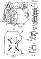
- the blocking element 8 (see Fig. 3) comprises a plate of limited thickness, being substantially flat and comprising plastics material and having a series of eight dished or drawn portions 36 which project from the plane of the plate and which are aligned in two mutually perpendicular lines.
- the eight dished portions 36 are grouped in four pairs each disposed on one of the four halves of the two lines.
- the eight dished portions 36 are capable of being snapped into eight corresponding openings or slots 37 (see Fig. 2) which are provided in the bottom 11 of the container 9, when the blocking element 8 is mounted on the cartridge 6.
- the blocking clement 8 comprises a first limb portion 38 see Fig.
- the blocking element 8 comprises a second limb portion 39 which is opposite to the first limb portion 38 and which is arranged to cover the channel or groove 21 in which the spring 19 is received.
- the blocking element 8 In order to fit the blocking element 8, it is placed against the bottom 11 of the container 9 with the dished portions 36 in register with the openings 37. A moderate pressure is now applied to force the portions 36 to engage into the openings 37. As the portions 36 engage the corresponding openings 37, the portions 36 press against the bottom of the flange 28, which is raised with the ribbon 7 until the upper edge of the ribbon 7 bears against the ribs 29. The element 8 is in contact with the bottom 11 and the supply reel 25 is held with the ribbon 7 against the ribs 29.
- first and second limb portions 38 totally cover the grooves or channels 21 and 23 and partially cover the opening 31, thereby preventing the spring 19, the fixed abutment 24 and the sensing element 32 from engaging into the respective grooves or openings, as shown in Figure 1.
- a free corner 41 of the element 8 is gripped with one hand and, by pulling it strongly away from the bottom 11, the portions 36 come out of the respective openings 37, whereby the flange 38 moves downwardly until it touches the bottom 11 and the upper edge of the ribbon 7 is disengaged from the ribs 29 and the cartridge 6 is ready to be fitted to the machine.
- the blocking element 8 is sufficiently thin to allow the cartridges 6 to be stacked when their elements 8 are fitted more or less exactly as they stack without their blocking elements.
Abstract
Description
- The present invention relates to a cartridge for a typing ribbon with a blocking element, comprising a container in which a ribbon supply reel is rotatable and a blocking element acting between the reel and the container to prevent, the reel from winding when the cartridge is not mounted on a typewriter or other typing machine.
- A cartridge is known, in which a blocking element is incerted in a groove or channel disposed in the container in the region of the supply reel, so as to act between the lower part of the cover and the upper edge of the ribbon, thus compressing the supply reel against the bottom of the container. The blocking element thus prevents the typing ribbon from unwinding when that is not wanted. If however the user operates the manual forward feed disc, rotating it can cause the ribbon to feed forward, with a certain amount of difficulty. The known cartridge, with the specific blocking element, suffers from the disadvantage that, if the user is not paying attention, he can fit the cartridge to a machine with the blocking element still in position. The ribbon feed devices of the machine thus cause rotary movement and forward feed of the ribbon. However, since the supply reel is subjected to friction and restrained or checked, in the long run problems occur such as excessive wear of the ribbon feed device, as well as the possibility of breakage of the ribbon and the device itself.
- The object of the present invention is therefore to provide a cartridge with a blocking element, which is simple, reliable, and inexpensive and which prevents the cartridge from being fitted with the blocking element still in position.
- The cartridge according to the present invention is characterised in that the blocking element comprises at least one portion capable of preventing the cartridge from being fitted to the machine.
- The invention will now be described in more detail, by way of example, with reference to the accompanying drawings, in which:
- Fig. 1 is a plan view of part of a cartridge with a blocking element mounted on the cartridge,
- Fig. 2 shows a side view in cross-section of part of the cartridge shown in Fig. 1,
- Fig. 3 shows a plan view on an enlarged scale of the blocking element shown in Fig. 1,
- Fig. 4 shows a partly sectional view of some details of Fig.l, and
- Fig. 5 shows a partly sectional view of further details from Fig. 1.
- Referring to Fig. 1, a
removable cartridge 6 holds atyping ribbon 7 and a blockingelement 8 is mounted on the cartridge. Thecartridge 6 comprises acontainer 9 having abottom 11, afront wall portion 12, arear wall portion 13, twoside wall portions 14 and acover 16 which closes the container at the top thereof. Thecartridge 6 has twoarms rear wall portion 13, and it is normally removably fixed on a typewriter by means of aleaf spring 19 which is engaged in a groove or channel 21 in thefront wall portion 12 and holds two grooves orchannels arms fixed abutments 24 on the machine. - Housed in the
container 9 is asupply reel 25, on which thetyping ribbon 7 is wound. Thesupply reel 25 comprises a hub 26 (Fig. 2) which is rotatable about asleeve 27 which projects from thebottom 11, and aflange 28 which is fixed to the lower end of thehub 26. - The
cover 16 comprises fourribs 29 which project inwardly of thecartridge 6 and which are disposed at 90° relative to each other and which are capable of co-operating with the upper edge of theribbon 7 when theblocking element 8 is mounted on thecartridge 6. Only twosuch ribs 29 can be seen in the drawing. - The arm 18 (see Fig. 1) comprises a seat opening 31 for housing a
sensing element 32 having a lever 33 (Fig. 4), which is movable from a first position shown in solid lines in Fig. 4, which indicates that thecartridge 6 is not present, to a second position as shown in broken lines, which indicates that thecartridge 6 is fitted on the machine. Thecartridge 6 is substantially similar to that described in the present applicants' Italian patent No. 1 024 899 granted on 20th July 1978, and will therefore not be described in greater detail herein. - The blocking element 8 (see Fig. 3) comprises a plate of limited thickness, being substantially flat and comprising plastics material and having a series of eight dished or drawn
portions 36 which project from the plane of the plate and which are aligned in two mutually perpendicular lines. The eight dishedportions 36 are grouped in four pairs each disposed on one of the four halves of the two lines. The eight dishedportions 36 are capable of being snapped into eight corresponding openings or slots 37 (see Fig. 2) which are provided in thebottom 11 of thecontainer 9, when the blockingelement 8 is mounted on thecartridge 6. Theblocking clement 8 comprises afirst limb portion 38 see Fig. 1) which is capable of covering the groove orchannel 23 and in part the seat opening 31, in such a manner as to prevent theabutment 24 engaging with thechannel 23 and engagement of thesensing element 32 in theopening 31. In addition, theblocking element 8 comprises asecond limb portion 39 which is opposite to thefirst limb portion 38 and which is arranged to cover the channel or groove 21 in which thespring 19 is received. - In order to fit the
blocking element 8, it is placed against thebottom 11 of thecontainer 9 with thedished portions 36 in register with theopenings 37. A moderate pressure is now applied to force theportions 36 to engage into theopenings 37. As theportions 36 engage thecorresponding openings 37, theportions 36 press against the bottom of theflange 28, which is raised with theribbon 7 until the upper edge of theribbon 7 bears against theribs 29. Theelement 8 is in contact with thebottom 11 and thesupply reel 25 is held with theribbon 7 against theribs 29. At the same time, the first andsecond limb portions 38 totally cover the grooves orchannels 21 and 23 and partially cover theopening 31, thereby preventing thespring 19, the fixedabutment 24 and thesensing element 32 from engaging into the respective grooves or openings, as shown in Figure 1. - To remove the blocking
element 8 from thecartridge 6, afree corner 41 of theelement 8 is gripped with one hand and, by pulling it strongly away from thebottom 11, theportions 36 come out of therespective openings 37, whereby theflange 38 moves downwardly until it touches thebottom 11 and the upper edge of theribbon 7 is disengaged from theribs 29 and thecartridge 6 is ready to be fitted to the machine. - The blocking
element 8 is sufficiently thin to allow thecartridges 6 to be stacked when theirelements 8 are fitted more or less exactly as they stack without their blocking elements.
Claims (8)
Applications Claiming Priority (2)
| Application Number | Priority Date | Filing Date | Title |
|---|---|---|---|
| IT6772882 | 1982-06-07 | ||
| IT67728/82A IT1157030B (en) | 1982-06-07 | 1982-06-07 | CARTRIDGE FOR A WRITING TAPE WITH CONTRAST ELEMENT OF WRITING MACHINES |
Publications (3)
| Publication Number | Publication Date |
|---|---|
| EP0096545A2 true EP0096545A2 (en) | 1983-12-21 |
| EP0096545A3 EP0096545A3 (en) | 1984-08-29 |
| EP0096545B1 EP0096545B1 (en) | 1987-01-21 |
Family
ID=11304827
Family Applications (1)
| Application Number | Title | Priority Date | Filing Date |
|---|---|---|---|
| EP83303190A Expired EP0096545B1 (en) | 1982-06-07 | 1983-06-02 | Typing ribbon cartridge with blocking element |
Country Status (4)
| Country | Link |
|---|---|
| US (1) | US4511271A (en) |
| EP (1) | EP0096545B1 (en) |
| DE (1) | DE3369282D1 (en) |
| IT (1) | IT1157030B (en) |
Cited By (1)
| Publication number | Priority date | Publication date | Assignee | Title |
|---|---|---|---|---|
| GB2170778A (en) * | 1984-12-31 | 1986-08-13 | Canon Kk | Positioning ink-ribbon cassettes |
Families Citing this family (9)
| Publication number | Priority date | Publication date | Assignee | Title |
|---|---|---|---|---|
| US4676678A (en) * | 1984-02-21 | 1987-06-30 | Kabushiki Kaisha Toshiba | Ribbon cassette cartridge having a lid and a locator slot |
| JPH07106657B2 (en) * | 1984-05-15 | 1995-11-15 | 株式会社東芝 | Ribbon storage cassette |
| JPS6147659U (en) * | 1984-08-31 | 1986-03-31 | シチズン時計株式会社 | ribbon cartridge |
| JPS63306067A (en) * | 1987-06-08 | 1988-12-14 | スター精密株式会社 | Heat transfer printer |
| JPH0719805Y2 (en) * | 1989-02-08 | 1995-05-10 | ブラザー工業株式会社 | Printer |
| JPH02231183A (en) * | 1989-03-03 | 1990-09-13 | Brother Ind Ltd | Ribbon cassette rocking device |
| US5595447A (en) | 1992-10-13 | 1997-01-21 | Seiko Epson Corporation | Tape cartridge and printing device having print medium cartridge |
| US6113291A (en) * | 1998-08-07 | 2000-09-05 | Axiohm Transaction Solutions, Inc. | Ribbon cassette having housing with integrally formed biasing fingers and coaxial spools |
| US8882371B2 (en) | 2010-10-28 | 2014-11-11 | Zih Corp. | Printer with printhead assembly, clutch assembly, and printer ribbon transport assembly |
Citations (2)
| Publication number | Priority date | Publication date | Assignee | Title |
|---|---|---|---|---|
| DE2950270A1 (en) * | 1978-12-26 | 1980-07-10 | Royal Business Machines | RIBBON CASSETTE WITH INTEGRATED REEL LOCK |
| DE3128069A1 (en) * | 1980-07-28 | 1982-03-04 | SCM Corp., 10017 New York, N.Y. | RELEASABLE RIBBON BLOCKING DEVICE |
Family Cites Families (4)
| Publication number | Priority date | Publication date | Assignee | Title |
|---|---|---|---|---|
| US3074545A (en) * | 1961-06-16 | 1963-01-22 | Ibm | Container |
| IT1024899B (en) * | 1974-11-25 | 1978-07-20 | Olivetti Ing C S P A | REMOVABLE CARTRIDGE FOR A CAREON TAPE OF TELESCRIPTING ACCOUNTING MACHINES AND SIMILAR OFFICE MACHINES |
| US4272202A (en) * | 1978-09-20 | 1981-06-09 | Data Card Corporation | Ribbon cartridge with broken unidirectional friction drive and self cleaning gears |
| US4401394A (en) * | 1981-10-13 | 1983-08-30 | Xerox Corporation | Universal end of ribbon sensing system |
-
1982
- 1982-06-07 IT IT67728/82A patent/IT1157030B/en active
-
1983
- 1983-06-02 DE DE8383303190T patent/DE3369282D1/en not_active Expired
- 1983-06-02 EP EP83303190A patent/EP0096545B1/en not_active Expired
- 1983-06-07 US US06/501,819 patent/US4511271A/en not_active Expired - Lifetime
Patent Citations (2)
| Publication number | Priority date | Publication date | Assignee | Title |
|---|---|---|---|---|
| DE2950270A1 (en) * | 1978-12-26 | 1980-07-10 | Royal Business Machines | RIBBON CASSETTE WITH INTEGRATED REEL LOCK |
| DE3128069A1 (en) * | 1980-07-28 | 1982-03-04 | SCM Corp., 10017 New York, N.Y. | RELEASABLE RIBBON BLOCKING DEVICE |
Non-Patent Citations (1)
| Title |
|---|
| Italian Patent No. 1024899 from Applicant * |
Cited By (1)
| Publication number | Priority date | Publication date | Assignee | Title |
|---|---|---|---|---|
| GB2170778A (en) * | 1984-12-31 | 1986-08-13 | Canon Kk | Positioning ink-ribbon cassettes |
Also Published As
| Publication number | Publication date |
|---|---|
| US4511271A (en) | 1985-04-16 |
| EP0096545B1 (en) | 1987-01-21 |
| IT1157030B (en) | 1987-02-11 |
| EP0096545A3 (en) | 1984-08-29 |
| DE3369282D1 (en) | 1987-02-26 |
| IT8267728A0 (en) | 1982-06-07 |
Similar Documents
| Publication | Publication Date | Title |
|---|---|---|
| US7168650B2 (en) | Roll holder device for supporting recording material roll and supply magazine with the same | |
| EP0096545B1 (en) | Typing ribbon cartridge with blocking element | |
| EP0078369B1 (en) | Printer ribbon cartridge and loading arrangement therefor | |
| KR930003195B1 (en) | Disk cartridge | |
| EP0121908B1 (en) | A paper supply system of copying machine and a paper supply cassette | |
| US20030102341A1 (en) | Mechanism for engaging portable equipment against a belt clip | |
| US3272304A (en) | Typewriter ribbon package | |
| EP0531113A2 (en) | Case for a disc cartridge | |
| US4838535A (en) | Sheet feeding device with detachable holder means for thick cut sheets | |
| GB1584058A (en) | Storae cases | |
| US3977511A (en) | Ribbon loading device | |
| US4402621A (en) | Ribbon cartridge with ribbon guide arms | |
| EP0170504B1 (en) | Print ribbon cassette | |
| US3396828A (en) | Ribbon cartridge | |
| EP0045082A2 (en) | Magnetic recording tape cartridge | |
| GB2219281A (en) | Printing apparatus; collecting & feed devices | |
| US5163766A (en) | Printer device | |
| EP0246067B1 (en) | Sheet feed apparatus and cartridge therefor | |
| US5433540A (en) | Combined spool retainer and installation device | |
| US3481445A (en) | Cartridge ribbon supply | |
| EP0201156A2 (en) | Tape cassette | |
| US4990006A (en) | Holder of a ribbon for typewriters or similar machines | |
| CA1222727A (en) | Container for photographic prints | |
| JPH0434511B2 (en) | ||
| EP0189257B1 (en) | Tape cassette reel |
Legal Events
| Date | Code | Title | Description |
|---|---|---|---|
| PUAI | Public reference made under article 153(3) epc to a published international application that has entered the european phase |
Free format text: ORIGINAL CODE: 0009012 |
|
| AK | Designated contracting states |
Designated state(s): DE FR GB |
|
| PUAL | Search report despatched |
Free format text: ORIGINAL CODE: 0009013 |
|
| AK | Designated contracting states |
Designated state(s): DE FR GB |
|
| 17P | Request for examination filed |
Effective date: 19850213 |
|
| GRAA | (expected) grant |
Free format text: ORIGINAL CODE: 0009210 |
|
| AK | Designated contracting states |
Kind code of ref document: B1 Designated state(s): DE FR GB |
|
| REF | Corresponds to: |
Ref document number: 3369282 Country of ref document: DE Date of ref document: 19870226 |
|
| PLBE | No opposition filed within time limit |
Free format text: ORIGINAL CODE: 0009261 |
|
| STAA | Information on the status of an ep patent application or granted ep patent |
Free format text: STATUS: NO OPPOSITION FILED WITHIN TIME LIMIT |
|
| 26N | No opposition filed | ||
| PGFP | Annual fee paid to national office [announced via postgrant information from national office to epo] |
Ref country code: GB Payment date: 19970527 Year of fee payment: 15 |
|
| PGFP | Annual fee paid to national office [announced via postgrant information from national office to epo] |
Ref country code: DE Payment date: 19970606 Year of fee payment: 15 |
|
| PGFP | Annual fee paid to national office [announced via postgrant information from national office to epo] |
Ref country code: FR Payment date: 19970610 Year of fee payment: 15 |
|
| PG25 | Lapsed in a contracting state [announced via postgrant information from national office to epo] |
Ref country code: GB Free format text: LAPSE BECAUSE OF NON-PAYMENT OF DUE FEES Effective date: 19980602 |
|
| GBPC | Gb: european patent ceased through non-payment of renewal fee |
Effective date: 19980602 |
|
| PG25 | Lapsed in a contracting state [announced via postgrant information from national office to epo] |
Ref country code: FR Free format text: LAPSE BECAUSE OF NON-PAYMENT OF DUE FEES Effective date: 19990226 |
|
| PG25 | Lapsed in a contracting state [announced via postgrant information from national office to epo] |
Ref country code: DE Free format text: LAPSE BECAUSE OF NON-PAYMENT OF DUE FEES Effective date: 19990401 |
|
| REG | Reference to a national code |
Ref country code: FR Ref legal event code: ST |