EP0095816A2 - Ausricht- und Förderanlage für Gegenstände - Google Patents
Ausricht- und Förderanlage für Gegenstände Download PDFInfo
- Publication number
- EP0095816A2 EP0095816A2 EP83200773A EP83200773A EP0095816A2 EP 0095816 A2 EP0095816 A2 EP 0095816A2 EP 83200773 A EP83200773 A EP 83200773A EP 83200773 A EP83200773 A EP 83200773A EP 0095816 A2 EP0095816 A2 EP 0095816A2
- Authority
- EP
- European Patent Office
- Prior art keywords
- articles
- article
- belts
- bed
- conveying
- Prior art date
- Legal status (The legal status is an assumption and is not a legal conclusion. Google has not performed a legal analysis and makes no representation as to the accuracy of the status listed.)
- Withdrawn
Links
Images


Classifications
-
- B—PERFORMING OPERATIONS; TRANSPORTING
- B65—CONVEYING; PACKING; STORING; HANDLING THIN OR FILAMENTARY MATERIAL
- B65G—TRANSPORT OR STORAGE DEVICES, e.g. CONVEYORS FOR LOADING OR TIPPING, SHOP CONVEYOR SYSTEMS OR PNEUMATIC TUBE CONVEYORS
- B65G47/00—Article or material-handling devices associated with conveyors; Methods employing such devices
- B65G47/22—Devices influencing the relative position or the attitude of articles during transit by conveyors
- B65G47/24—Devices influencing the relative position or the attitude of articles during transit by conveyors orientating the articles
- B65G47/244—Devices influencing the relative position or the attitude of articles during transit by conveyors orientating the articles by turning them about an axis substantially perpendicular to the conveying plane
Definitions
- This invention relates to article alignment and conveying apparatus for aligning elongated articles in single file in a plurality of transversely spaced lanes and moving the articles while in the lanes past a work station.
- One of the objects of this invention is to provide a very efficient high volume mechanism for accurately aligning the articles in a longitudinal direction in a plurality of spaced lanes so that a large volume of articles may be processed by automatic equipment.
- An additional object of this invention is to provide an article alignment and conveying apparatus that is capable of being rapidly and efficiently adjusted to handle more than one size of product.
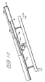
- FIG. 1 an article alignment and conveying apparatus generally designated with the numeral 10 for conveying elongated articles 12 past a work station 13 in which the articles 12 are aligned in single file in a plurality of transversely spaced lanes as the articles move past a work station.
- the articles 12 are preferably elongated potato sections referred to as "french fries”. Other similar articles may be processed by apparatus 10.
- the objective of the apparatus is to be able to handle a large volume of french fries and to align the french fries very accurately with respect to the lanes as they pass the work station 13 so that very accurate, large volume processing of the articles can be accomplished.
- automatic inspection equipment 46 is located at the work station 13.
- a selective article treatment device 48 may also be positioned at or near the work station 13 for removing or treating undesirable articles.
- the apparatus 10 includes an article feed means 14 for initially receiving the elongated articles 12 generally in an unseparated or jumbled mass at a receiving section 22 and for separating the articles into a plurality of channels 32 corresponding to transversely spaced lanes and discharging the articles 12 onto an elongated belt conveyor 40.
- the article feed means 14 includes a support framework 16 (Figs. 3 and 12) for supporting a vibratory conveying bed frame 18 at an elevated inclined orientation with a plurality of stepped vibratory beds 20a, 20b, 20c, and 20d for progressively separating and spreading the articles 12.
- the vibratory bed 20a forms a receiving station 22 for initially receiving the articles 13 from some type of random article feed.
- the articles 12 As the articles 12 are vibrated down the stepped beds 20a-d, the articles progress through a separation station 24 formed by the step beds 20a, 20b, 20c, and 20d with the last step bed 20d forming a discharge section 26 for discharging the articles from channels 32 onto the elongated belt conveyor 40.
- Each of the stepped beds 20a-d include one or more dividers 28 and troughs 30 (Fig. 3).
- the number of dividers and troughs 28 and 30 respectively progressively increase from one stepped bed 20a-d to another to progressively subdivide the articles into narrower troughs 28.
- Bed 20d is formed by V-shaped channels 32 that form both the troughs 30 and the dividers 28.
- the channels 32 correspond with the lanes that extend to pass the work station 13. Additional stepped beds or stages may be provided as needed.
- the elongated belt conveyor 40 extends from the discharge section 26 of the article feed means 14 past the work station 13 for further aligning the product longitudinally and registering the articles with respect to the lanes and to prevent the articles from moving laterally as the articles are being transferred from the discharge section 26 to the elongated belt conveyor 40.
- the elongated belt conveyor 40 includes a framework 41 that extends from a receiving end 42 to a discharge end 43.
- the elongated belt conveyor includes a first set of narrow belts 50 and a second set of narrow belts 52 (Figs. 6-11) that are placed in parallel abutting relationship alternately across the conveyor 40 to form a wide article support surface 75 extending from the receiving end 42 to the discharge end 43.
- the belts 50 and 52 are each formed of continuous plastic material that is somewhat lengthwise stretchable and having smooth surfaces.
- the elongated belt conveyor 40 includes drive means having a front pulley drum 55 adjacent the receiving end 42 and a rear pulley drum 57 adjacent the discharge end 43 for stretchably receiving the alternating narrow belts 50 and 52.
- the narrow belts 50 and 52 are illustrated in cross sections in Figs. 6-11.
- Each narrow belt 50 and 52 is preferably of rectangular cross section which includes an upper surface, a lower surface and side surfaces.
- the surfaces of belts 50 and 52 are quite smooth enabling one belt to easily slide vertically with respect to the other belt.
- the narrow belt 52 has an inverted U-shaped groove 71 formed therein.
- the upper surfaces of the belts 50 and 52 cooperatively form a wide article conveying belt surface 75 that extends from the receiving end 43 to the discharge end 43 for carrying the articles past the work station 13.
- the pulley drums 55 and 57 include spaced annular pulley ribs 55 that are illustrated in Figs. 1, 8 and 9 that have widths that are complementary and project into the groove 71 of the narrow belts 52.
- the pulley drums 55 and 57 are mounted on shafts 78 with end hubs 80 that are slidably mounted on the shafts to enable the drums 55 and 57 to be moved axially along the shaft 78 to shift the belts 50 and 52 laterally with respect to the longitudinal direction of the conveyor 40.
- a set screw 82 is provided in the hubs 80 to affix the drums 50 and 57 at one of two lateral positions.
- the adjustable pulley drums 55 and 57 enable the belts to be shifted laterally in unison as desired by releasing and resetting the set screw 82 in one of the two lateral positions.
- the elongated belt conveyor 40 further includes a first bed section 85 (Figs. 1, 2 and 5) for receiving and slidably supporting the narrow belts 50 and 52 adjacent the receiving end 42.
- the first bed section 85 includes a subframe that is pivotally mounted through pivots 88 to enable the subframe to be pivoted to an upward operative condition (Fig. 2) in which an upper plate 89 of the bed section 85 engages and lifts the narrow belts 50 and 52 and a lower position (Fig. 5) to enable the belts to be moved laterally.
- the upper plate 89 has a plurality of parallel longitudinal grooves formed therein to define valleys 92 and ridges 94 (Figs. 6 and 10). Both the valleys 92 and ridges 94 are designed to slidably support the narrow belts 50 and 52 in which the wide article conveying surface 75 is corrugated along the first bed section 85 so that the articles 12 are aligned longitudinally in the valleys 92 as illustrated in Fig. 6. In Fig. 6 the narrow belts 52 are slidably mounted in the valleys 92 and the narrow belts 50 are slidably mounted on the ridges 94.
- the ridges 94 taper to the valleys 92 so that the upper surfaces of the belts 50 and 52 form a flat article support surface 75 as illustrated in Figs. 7 and 11 as the articles are moved past the work station 13.
- the articles are quite active and still vibrating.
- the valleys 92 are aligned with the channels 32 so that the articles 13 sequentially fall in line into the valleys 92.
- the narrow belts on the ridge 94 project upward confining the articles to prevent the articles from moving laterally and to register the articles with respect to the lanes so that the articles move past the work station with a high degree of precision with respect to their transverse spacing and longitudinal orientation.
- the elongated belt conveyor 40 further includes a second bed section 97 (Figs. 1, 2, 5, 7 and 11) that is immediately downstream of the first bed section 85 for receiving and supporting the narrow belts 50 and 52 in which the belts are supported so that their upper surfaces form the substantially flat conveying surface 75 with the articles precisely aligned and spaced as they move past the work station 13.
- a second bed section 97 (Figs. 1, 2, 5, 7 and 11) that is immediately downstream of the first bed section 85 for receiving and supporting the narrow belts 50 and 52 in which the belts are supported so that their upper surfaces form the substantially flat conveying surface 75 with the articles precisely aligned and spaced as they move past the work station 13.
- the apparatus 10 is designed so that the belts 50 and 52 may be shifted laterally with respect to the first bed section 85 so that either the narrow belts 50 or the narrow belts 52 will ride in the valleys 92.
- the narrow belts 52 ride in the valleys 92 whereas in Fig. 10, the narrow belts 50 ride in the valleys 52.
- the narrow belts 52 ride on the ridges 94 with the ridges 94 projecting into the belt grooves 91.
- the lateral shift is accomplished by releasing the set screws 82 and moving the pulley drums 55 and 57 laterally on the shafts 78 and then resetting the set screws 82.
- the narrow belt 52 is wider than the narrow belt 50 so that the apparatus can be utilized for two different width lanes.
- the narrow belt 52 is 5/8" wide and the narrow belt 50 is 3/8" wide. Under such a condition, french fries of approximately 1/2" thickness will ride in the valleys 92 as illustrated in Fig. 6 whereas in Fig. 10 french fries of approximately 1/4" will reside in the valleys 92.
- the elongated articles While riding over the first bed section 85, the elongated articles are registered laterally and stabilized and aligned longitudinally to the lanes. As the belts move in unison toward the second bed section 97, the raised belts are progressively lowered so that as the belts pass over the second bed section 97 the upper surfaces of the belts 50 and 52 are substantially coincident forming the flat conveying surface 95 (Figs. 7 and 11).
- the elongated belt conveyor 40 further includes an overhead frame 98 (Figs. 1, 2 and 5) that extends over the first bed section 85.
- the overhead frame has a plurality of fingers 100 that extend downward over the ridges 94 to deflect any crosswise oriented elongated articles into the valleys 92.
- the fingers 100 are staggered in diagonal rows as illustrated in Fig. 4 so as to maximize the opportunity for a crosswise oriented article to be deflected into a valley 92.
- a transverse brush 102 is mounted at approximately 45° with respect to the longitudinal movement of the narrow belts 50, 52 for transversely moving any crosswise articles or piggyback articles laterally across the surface 75 and hopefully into an unfilled valley 92.
- the brush 102 is journalled in journal bearings 103 on opposite sides of the bed and is rotated counterclockwise as shown in Fig. 1 to brush the piggyback or crosswise articles across the corrugated conveying surface 75. If the articles do not fall into an unfilled valley 92 as they progress across the surface 75, then they are deflected into a recovery container 105 (Fig. 1) along one side of the elongated belt conveyor 40.
Landscapes
- Engineering & Computer Science (AREA)
- Mechanical Engineering (AREA)
- Attitude Control For Articles On Conveyors (AREA)
- Structure Of Belt Conveyors (AREA)
Applications Claiming Priority (2)
| Application Number | Priority Date | Filing Date | Title |
|---|---|---|---|
| US06/383,752 US4485912A (en) | 1982-06-01 | 1982-06-01 | Article alignment and conveying apparatus |
| US383752 | 2006-05-16 |
Publications (2)
| Publication Number | Publication Date |
|---|---|
| EP0095816A2 true EP0095816A2 (de) | 1983-12-07 |
| EP0095816A3 EP0095816A3 (de) | 1985-05-15 |
Family
ID=23514566
Family Applications (1)
| Application Number | Title | Priority Date | Filing Date |
|---|---|---|---|
| EP83200773A Withdrawn EP0095816A3 (de) | 1982-06-01 | 1983-05-31 | Ausricht- und Förderanlage für Gegenstände |
Country Status (3)
| Country | Link |
|---|---|
| US (1) | US4485912A (de) |
| EP (1) | EP0095816A3 (de) |
| CA (1) | CA1198391A (de) |
Cited By (1)
| Publication number | Priority date | Publication date | Assignee | Title |
|---|---|---|---|---|
| NL1032988C2 (nl) * | 2006-12-04 | 2008-06-06 | Kaak Johan H B | Transportinrichting. |
Families Citing this family (13)
| Publication number | Priority date | Publication date | Assignee | Title |
|---|---|---|---|---|
| US4889241A (en) * | 1987-11-30 | 1989-12-26 | Frito-Lay, Inc. | Discharge chute with variable slope bottom for fragile article sorting system |
| US4831922A (en) * | 1988-05-25 | 1989-05-23 | Frito-Lay Inc. | Automated system for processing whole potatoes |
| SE8803116L (sv) * | 1988-09-06 | 1990-03-07 | Agec Ab | Metod och anordning foer storlekssortering av foeremaal |
| US5197607A (en) * | 1988-09-06 | 1993-03-30 | Reinhold Hakansson | Method and apparatus for grading objects in accordance to size |
| US5431289A (en) * | 1994-02-15 | 1995-07-11 | Simco/Ramic Corporation | Product conveyor |
| US5526437A (en) * | 1994-03-15 | 1996-06-11 | Key Technology, Inc. | Integrated food sorting and analysis apparatus |
| US5871080A (en) * | 1995-09-21 | 1999-02-16 | Planet Products Corporation | Product aligning system |
| US6000527A (en) * | 1998-06-04 | 1999-12-14 | Span Tech Llc | Product lane forming conveyor system and related method |
| US6152282A (en) * | 1999-02-01 | 2000-11-28 | Src Vision, Inc. | Laned conveyor belt |
| US6919122B2 (en) | 1999-07-08 | 2005-07-19 | Saint-Gobain Performance Plastics Corporation | Flexible composites with integral flights for use in high-temperature food processing equipment and methods for producing the same |
| US6923098B2 (en) * | 2001-01-23 | 2005-08-02 | Key Technology, Inc. | Method and apparatus for inspecting and cutting elongated articles |
| ITBO20030776A1 (it) * | 2003-12-23 | 2005-06-24 | Marchesini Group Spa | Dispositivo per il recupero e il riutilizzo di articoli |
| CN109996745A (zh) | 2016-11-29 | 2019-07-09 | 美国圣戈班性能塑料公司 | 复合带材料 |
Citations (4)
| Publication number | Priority date | Publication date | Assignee | Title |
|---|---|---|---|---|
| US1923713A (en) * | 1932-09-19 | 1933-08-22 | Alfred D Edgar | Fruit and vegetable assorting apparatus |
| FR1435765A (fr) * | 1964-04-02 | 1966-04-22 | Charles Nicolle Ets | Procédé et dispositif pour ranger des suppositoires stockés en vrac, dans les alvéoles d'un emballage de conditionnement |
| DE2139431A1 (de) * | 1971-08-06 | 1973-02-15 | Lichtenfeld & Co | Vorrichtung zum verpackungsgerechten gruppieren stabfoermiger gegenstaende |
| GB1416875A (en) * | 1972-11-13 | 1975-12-10 | Bain Ltd Martin Robertson | Methods of handling sticks and mechanism for handling such sticks |
Family Cites Families (12)
| Publication number | Priority date | Publication date | Assignee | Title |
|---|---|---|---|---|
| US1192832A (en) * | 1916-01-07 | 1916-07-25 | Willis S Sherman | Conveyer. |
| US1905700A (en) * | 1926-08-16 | 1933-04-25 | Nat Biscuit Co | Facing machine |
| US2456031A (en) * | 1946-04-10 | 1948-12-14 | E J Brach & Sons | Article arranging and advancing conveyer mechanism |
| GB742874A (en) * | 1949-11-16 | 1956-01-04 | British Ermeto Corp Ltd | Method of and means for uniformly orientating objects |
| US2764274A (en) * | 1955-07-07 | 1956-09-25 | Owens Illinois Glass Co | Article handling apparatus |
| US3180476A (en) * | 1962-01-29 | 1965-04-27 | American Mach & Foundry | Corrector for misaligned and overturned rolls |
| CH463083A (de) * | 1967-11-07 | 1968-09-30 | Bauwerk Bodenbelagsind Ag | Einrichtung zum gleichsinnigen Ausrichten von Parkettleisten |
| US3545588A (en) * | 1968-01-15 | 1970-12-08 | Helen Emily Corley | Scale to labeller feed |
| US3623592A (en) * | 1968-07-18 | 1971-11-30 | Brex Corp | Fruit feed system and method |
| US3653509A (en) * | 1969-12-09 | 1972-04-04 | Research Corp | Sizing apparatus |
| US4011939A (en) * | 1975-09-26 | 1977-03-15 | Dynaloc Corporation | Closed loop cleated belt/grooved pulley conveyor system |
| JPS594992Y2 (ja) * | 1978-07-14 | 1984-02-15 | 株式会社リコー | シ−ト搬送用ベルト装置 |
-
1982
- 1982-06-01 US US06/383,752 patent/US4485912A/en not_active Expired - Lifetime
-
1983
- 1983-05-31 CA CA000429346A patent/CA1198391A/en not_active Expired
- 1983-05-31 EP EP83200773A patent/EP0095816A3/de not_active Withdrawn
Patent Citations (4)
| Publication number | Priority date | Publication date | Assignee | Title |
|---|---|---|---|---|
| US1923713A (en) * | 1932-09-19 | 1933-08-22 | Alfred D Edgar | Fruit and vegetable assorting apparatus |
| FR1435765A (fr) * | 1964-04-02 | 1966-04-22 | Charles Nicolle Ets | Procédé et dispositif pour ranger des suppositoires stockés en vrac, dans les alvéoles d'un emballage de conditionnement |
| DE2139431A1 (de) * | 1971-08-06 | 1973-02-15 | Lichtenfeld & Co | Vorrichtung zum verpackungsgerechten gruppieren stabfoermiger gegenstaende |
| GB1416875A (en) * | 1972-11-13 | 1975-12-10 | Bain Ltd Martin Robertson | Methods of handling sticks and mechanism for handling such sticks |
Cited By (2)
| Publication number | Priority date | Publication date | Assignee | Title |
|---|---|---|---|---|
| NL1032988C2 (nl) * | 2006-12-04 | 2008-06-06 | Kaak Johan H B | Transportinrichting. |
| WO2008069642A3 (en) * | 2006-12-04 | 2008-10-30 | Kaak Johan H B | Conveyance device |
Also Published As
| Publication number | Publication date |
|---|---|
| CA1198391A (en) | 1985-12-24 |
| EP0095816A3 (de) | 1985-05-15 |
| US4485912A (en) | 1984-12-04 |
Similar Documents
| Publication | Publication Date | Title |
|---|---|---|
| US4485912A (en) | Article alignment and conveying apparatus | |
| KR101932058B1 (ko) | 과대 소포들의 제거를 위한 시프트 및 유지 컨베이어 조립체 | |
| US3770123A (en) | Method and apparatus for grading shrimp | |
| US5291983A (en) | Apparatus for aligning and uniformly orienting fish | |
| US3933086A (en) | Apparatus for separating dried fruit aggregates | |
| US3628648A (en) | Compact orienting and singulating system for irregular elongated objects such as potatoes | |
| US3799336A (en) | Method and apparatus for treating discrete articles | |
| US3068989A (en) | Apparatus for handling substantially flat articles | |
| US4129207A (en) | Product alignment mechanism | |
| EP0294070A2 (de) | Gerät zum Handhaben von Körpern allgemein zylindrischer Gestalt | |
| US4919273A (en) | Apparatus for sorting metal bars by length | |
| US3752293A (en) | Article grouping system | |
| US4147249A (en) | Machine for handling containers continuously passing on a moving band and, more particularly, glass bottles | |
| FI63911C (fi) | Saett och anordning foer arrangemang av styckformiga partiklari en koe bildad av enskilda partiklar | |
| EP0646534B1 (de) | Ausrichten von länglichen Gegenständen | |
| JPH02100906A (ja) | 人参などのような比較的短くて先細り形状の根葉類供給装置 | |
| KR20160034087A (ko) | 과일 선별기 | |
| US20230174323A1 (en) | Apparatus and methods for transferring fragile items at selectively variable flow rates | |
| DE19945037A1 (de) | Vorrichtung zum Ausrichten und gegebenenfalls Sortieren von länglichen Partikeln | |
| US20240140716A1 (en) | Apparatus and methods for transferring fragile items at selectively variable flow rates | |
| JP2540135B2 (ja) | 青果物の小玉抜き装置 | |
| US2961095A (en) | Device for sorting articles by length, particularly for sorting cucumbers, beans, or the like | |
| CA2351888A1 (en) | Vegetable length grader with segmented roller | |
| JP2582960B2 (ja) | 作物の選別用搬送装置 | |
| US3478863A (en) | Corn ear orienting device |
Legal Events
| Date | Code | Title | Description |
|---|---|---|---|
| PUAI | Public reference made under article 153(3) epc to a published international application that has entered the european phase |
Free format text: ORIGINAL CODE: 0009012 |
|
| AK | Designated contracting states |
Designated state(s): BE CH DE FR GB LI NL |
|
| PUAL | Search report despatched |
Free format text: ORIGINAL CODE: 0009013 |
|
| AK | Designated contracting states |
Designated state(s): BE CH DE FR GB LI NL |
|
| 17P | Request for examination filed |
Effective date: 19850805 |
|
| 17Q | First examination report despatched |
Effective date: 19860524 |
|
| STAA | Information on the status of an ep patent application or granted ep patent |
Free format text: STATUS: THE APPLICATION IS DEEMED TO BE WITHDRAWN |
|
| 18D | Application deemed to be withdrawn |
Effective date: 19861004 |
|
| RIN1 | Information on inventor provided before grant (corrected) |
Inventor name: DAVIS, WALTER L. Inventor name: PERRY, VERNON L. Inventor name: CARMICHAEL, MURPHY D. |