EP0095662A1 - High-temperature nuclear reactor wherein the hot gas conduit is disconnectable from the reactor vessel - Google Patents
High-temperature nuclear reactor wherein the hot gas conduit is disconnectable from the reactor vessel Download PDFInfo
- Publication number
- EP0095662A1 EP0095662A1 EP83104921A EP83104921A EP0095662A1 EP 0095662 A1 EP0095662 A1 EP 0095662A1 EP 83104921 A EP83104921 A EP 83104921A EP 83104921 A EP83104921 A EP 83104921A EP 0095662 A1 EP0095662 A1 EP 0095662A1
- Authority
- EP
- European Patent Office
- Prior art keywords
- hot gas
- reactor
- pipeline
- vessel
- temperature nuclear
- Prior art date
- Legal status (The legal status is an assumption and is not a legal conclusion. Google has not performed a legal analysis and makes no representation as to the accuracy of the status listed.)
- Granted
Links
Images

Classifications
-
- G—PHYSICS
- G21—NUCLEAR PHYSICS; NUCLEAR ENGINEERING
- G21C—NUCLEAR REACTORS
- G21C13/00—Pressure vessels; Containment vessels; Containment in general
- G21C13/02—Details
- G21C13/032—Joints between tubes and vessel walls, e.g. taking into account thermal stresses
-
- G—PHYSICS
- G21—NUCLEAR PHYSICS; NUCLEAR ENGINEERING
- G21C—NUCLEAR REACTORS
- G21C1/00—Reactor types
- G21C1/04—Thermal reactors ; Epithermal reactors
- G21C1/06—Heterogeneous reactors, i.e. in which fuel and moderator are separated
- G21C1/07—Pebble-bed reactors; Reactors with granular fuel
-
- Y—GENERAL TAGGING OF NEW TECHNOLOGICAL DEVELOPMENTS; GENERAL TAGGING OF CROSS-SECTIONAL TECHNOLOGIES SPANNING OVER SEVERAL SECTIONS OF THE IPC; TECHNICAL SUBJECTS COVERED BY FORMER USPC CROSS-REFERENCE ART COLLECTIONS [XRACs] AND DIGESTS
- Y02—TECHNOLOGIES OR APPLICATIONS FOR MITIGATION OR ADAPTATION AGAINST CLIMATE CHANGE
- Y02E—REDUCTION OF GREENHOUSE GAS [GHG] EMISSIONS, RELATED TO ENERGY GENERATION, TRANSMISSION OR DISTRIBUTION
- Y02E30/00—Energy generation of nuclear origin
- Y02E30/30—Nuclear fission reactors
Definitions
- the present invention relates to a nuclear power plant according to the preamble of the first claim. It is used to improve a nuclear power plant of the type described in DE-A-30 16 402 and to which reference is made here for the description of the general structure of such a plant.
- the possibility had already been shown there of accommodating a nuclear reactor of the type described with a certain space in a steel pressure vessel, as is also used for the known pressurized water reactors, and which represents a component which is completely mastered in its technology.
- the connection of the actual core container to the hot gas pipeline which carried the gases heated in it would be carried out as simple plug connections. Recent considerations have resulted in a simpler gas flow and, in addition, a stronger connection of the two components, while retaining the possibility of being able to separate them for repair purposes.
- the object of the present invention is to design the connection between the reactor vessel and the hot gas pipeline in such a way that the connection between the two can be released without special difficulties by means of remote-controlled tools, at the same time for the convenience disassembly and subsequent reassembly, a gap is created between the two components.
- the embodiment of the invention proposed in the second claim serves to more precisely guide the screws connecting the two Y components to facilitate reassembly, which is only ensured if the screws are threaded in both flanges.
- the threaded parts of the flanges must be separated from each other by an exact multiple of the thread pitch, which can be easily accomplished by the resilient arrangement of the one thread.
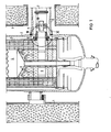
- the nuclear power plant consists, among other things, of an inner steel pressure vessel 2 arranged inside a concrete shield 1, inside and with the release of an annular gap an inner vessel 3 made of graphite and coal stone with a metallic shell is arranged, which represents the actual core vessel; this contains a core assembly 4 of, for example, spherical fuel elements, through which a gas, for example helium, serves as a heat transfer medium and flows from top to bottom, which heats up in the process. Via numerous small bores 5 made in the tank bottom, the gas finally arrives in a collecting space 6, from which it is supplied via a hot gas pipe 7, not shown here, to heat-consuming parts of the system, for example a heat exchanger.
- a gas for example helium
- the H technikgäsrohr admir 7 is also under Beibemik an annular gap, housed in a welded to the outer container 2 piece 8, wherein the nozzle is part of an intermediate container to the pressure vessel 2 with an unillustrated here components container (eg for receiving heat exchangers) is tightly connected.
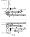
- Inner container 3 and hot gas pipeline 7 are provided with matching flanges 9 and 10, which are held together by screws 11 distributed over the circumference during operation.
- the screw 11 can be set in rotation in the desired direction by means of a bent articulated shaft 12, which is shaped at its end 13 and placed on a connector 8 for this purpose, in operation by one here Not shown lid is closed opening is aligned that from outside the pressure vessel 2 ent speaking remote-controlled tool, also not shown here, can be used.
- the screws 11 engage in a corresponding, threaded blind hole, while they are guided in the line flange 10 with play in a simple through hole.
- a double ring 16 is arranged on both sides of the flange 10 and is supported relative to the latter by springs 15, the halves of which are rigidly connected to one another by screws 17.
- the ring 16 located between the two flanges is provided with a threaded hole matching the screw 11. Due to the resilience of the springs 15, a distance is set automatically between the flange 9 and the ring 16, which is a multiple of the thread height of the screw 11, so that the latter is not only guided exactly during assembly work, but also easily in that thread to be met runs into flange 9.
- the hot gas pipe 7 (see FIG. 1) is provided with corrugated pipe compensators 18 to compensate for the thermal expansions occurring between the idle state at ambient temperature and the operating state at approx. 900 ° C (inside) or approx. 300 ° C (metallic outer pipe and compensators) that oppose an axial displacement of the line flange 10 away from the container flange 9 a defined resistance.
- hydraulic cylinders 19 (which are removed during reactor operation; distribution lines, control units, etc. have been omitted here) are also distributed uniformly over the circumference of the nozzle 8 on the outside thereof and are therefore more easily accessible for maintenance and repair ).
- a linkage 20 Via a linkage 20, the movement indicated by the arrow in its direction is on the line flange 10 and thus on the line itself transmitted, whereby the resistance to deformation of the bellows compensators 18 must be overcome.
- a gap between the latter and the hot gas pipeline 7 which facilitates the dismantling or assembly of the core container 3 is thus created.
- the ends of the linkage 20 are formed as centering pins 21 which, when reassembled, engage in 'holes for this purpose. In the bores in the container flange 9, center the line flange 10 on them and thus enable the two parts to be screwed together.
Abstract
Für eine Hochtemperatur-Kernenergieanlage, bei der innerhalb eines äußeren Reaktordruckbehälters (2) mit angeschweißtem Stutzen (8) der eigentliche Kernbehälter (3) und eine an diesem angeschlossene Heißgasrohrleitung (7) angeordnet sind, wird eine Vielzahl von über den Umfang der beidseitigen Flanschen (9, 10) verteilten Schraubverbindungen (11) vorgeschlagen, die über Gelenkwellen (12) durch zu diesem Zweck angelegte Öffnungen (14) von außerhalb des Stutzens (8) betätigt werden können. Ebenfalls über den Umfang verteilt sind an ihrem Ende (21) als Paßstifte ausgestaltete Gestänge (20) vorhanden, mittels derer durch Hydraulikzylinder (19) eine Kraft auf die Rohrleitung (7) ausgeübt werden kann. Dadurch wird nach Überwindung des Verformungswiderstandes von in der Rohrleitung angeordneten Kompensatoren ein die Montage und Demontage erleichternder Spalt zwischen Reaktorbehälter (3) und Heißgasrohrleitung (7) hergestellt.For a high-temperature nuclear power plant, in which the actual core container (3) and a hot gas pipe (7) connected to it are arranged within an outer reactor pressure vessel (2) with a welded socket (8), a large number of flanges ( 9, 10) distributed screw connections (11) are proposed, which can be actuated from the outside of the connection piece (8) via cardan shafts (12) through openings (14) created for this purpose. Also distributed over the circumference are rods (20) designed as dowel pins at their end (21), by means of which a force can be exerted on the pipeline (7) by hydraulic cylinders (19). As a result, after overcoming the deformation resistance of compensators arranged in the pipeline, a gap between the reactor vessel (3) and the hot gas pipeline (7) which facilitates assembly and disassembly is produced.
Description
Die vorliegende Erfindung betrifft eine Kernenergieanlage nach dem Oberbegriff des ersten Anspruchs. Sie dient der Verbesserung einer Kernenergieanlage derjenigen Art, wie sie in der DE-A-30 16 402 beschrieben worden ist und auf die hier für die Beschreibung des allgemeinen Aufbaues einer solchen Anlage Bezug genommen wird. In einer Alternativausführung war dort bereits die Möglichkeit gezeigt worden, einen Kernreaktor der beschriebenen Art unter Einhaltung eines gewissen Zwischenraumes in einem Stahldruckbehälter unterzubringen, wie er auch für die bekannten Druckwasserreaktoren benutzt wird und der ein in seiner Technik völlig beherrschtes Bauteil darstellt. In der angezogenen Veröffentlichung war davon ausgegangen worden, daß die Verbindung des eigentlichen Kernbehälters zu der die in ihm erhitzten Gase fortleitenden Heißgasrohrleitung als einfache Steckverbindungen ausgeführt werden würden. Neuere Überlegungen haben dazu geführt, daß eine einfachere Gasführung und dazu eine festere Verbindung der beiden Bauteile gefordert wird unter Beibehaltung der Möglichkeit, dieselben zu Reparaturzwecken trennen zu können.The present invention relates to a nuclear power plant according to the preamble of the first claim. It is used to improve a nuclear power plant of the type described in DE-A-30 16 402 and to which reference is made here for the description of the general structure of such a plant. In an alternative embodiment, the possibility had already been shown there of accommodating a nuclear reactor of the type described with a certain space in a steel pressure vessel, as is also used for the known pressurized water reactors, and which represents a component which is completely mastered in its technology. In the attracted publication it had been assumed that the connection of the actual core container to the hot gas pipeline which carried the gases heated in it would be carried out as simple plug connections. Recent considerations have resulted in a simpler gas flow and, in addition, a stronger connection of the two components, while retaining the possibility of being able to separate them for repair purposes.
Aufgabe der vorliegenden Erfindung ist die Ausgestaltung der Verbindung zwischen Reaktorbehälter und Heißgasrohrleitung derart, daß die Verbindung zwischen beiden ohne besondere Schwierigkeiten mittels fernbedienbarer Werkzeuge gelöst werden kann, wobei zugleich zur Erleichterung der Demontage und späteren erneuten Montage ein Spalt zwischen beiden Bauteilen hergestellt wird.The object of the present invention is to design the connection between the reactor vessel and the hot gas pipeline in such a way that the connection between the two can be released without special difficulties by means of remote-controlled tools, at the same time for the convenience disassembly and subsequent reassembly, a gap is created between the two components.
Die Lösung dieser Aufgabe erfolgt durch die im kennzeichnenden Teil des ersten Anspruchs angegebenen Mittel. Es entfällt die Notwendigkeit des Ausbaues von Teilen im Ringspalt zwischen Außen- und Innenbehälter, der nur schwer durchzuführen wäre. Da die Heißgasrohrleitung zum Ausgleich für die zwischen Normal- und Betriebstemperatur auftretenden Wärmedehnungen mit Vorrichtungen zum Ausgleich derselben, z.B. mit Wellrohrkompensatoren versehen ist, muß die hier geforderte Vorrichtung nur eine zur Überwindung des Verformungswiderstandes dieser Kompensatoren ausreichende Kraft aufbringen, um den Flansch der Rohrleitung von demjenigen am Innenbehälter um das erforderliche, nur geringe Maß zu entfernen.This object is achieved by the means specified in the characterizing part of the first claim. There is no need to remove parts in the annular gap between the outer and inner container, which would be difficult to carry out. Since the hot gas pipe to compensate for the thermal expansion occurring between normal and operating temperature with devices to compensate for it, e.g. is provided with corrugated pipe compensators, the device required here only has to exert a force sufficient to overcome the deformation resistance of these compensators in order to remove the flange of the pipeline from that on the inner container by the required, only slight amount.
Die im zweiten Anspruch vorgeschlagene Ausgestaltung der Erfindung dient einer exakteren Führung der die beiden-Y-Bauteile verbindenden Schrauben zur Erleichterung eines erneuten Zusammenbaus, die nur gewährleistet ist, wenn die Schrauben in beiden Flanschen in Gewinde geführt werden. Hierzu müssen die mit Gewinde versehenen Teile der Flansche um ein genaues Vielfaches der Gewindeganghöhe von einander entfernt sein, was sich durch die nachgiebige Anordnung des einen Gewindes ohne weiteres bewerkstelligen läßt.The embodiment of the invention proposed in the second claim serves to more precisely guide the screws connecting the two Y components to facilitate reassembly, which is only ensured if the screws are threaded in both flanges. For this purpose, the threaded parts of the flanges must be separated from each other by an exact multiple of the thread pitch, which can be easily accomplished by the resilient arrangement of the one thread.
Ein Ausführungsbeispiel der Erfindung ist in der Zeichnung dargestellt, und zwar zeigt
- Figur 1 den für das Verständnis der Erfindung notwendigen unteren Teil der angesprochenen Kernenergieanlage,
Figur 2 in vergrößertem Maßstab die Einzelheit X der Figur 1 undFigur 3 in abermals vergrößertem Maßstab die EinzelheitY
- FIG. 1 shows the lower part of the nuclear power plant mentioned, which is necessary for understanding the invention,
- Figure 2 on an enlarged scale, the detail X of Figure 1 and
- Figure 3 on a further enlarged scale, the detail Y
Die Kernenergieanlage besteht unter anderem aus einem innerhalb einer Betonabschirmung 1 angeordneten äußeren stählernen Druckbehälter 2 innerhalb dessen und unter Freilassung eines Ringspaltes ein aus Graphit und Kohlestein mit metallischer Hülle aufgebauter,Innenbehälter 3 angeordnet ist, der den eigentlichen Kernbehälter darstellt; dieser enthält einen Kernverband 4 aus beispielsweise kugelförmigen Brennelementen, der von oben nach unten von einem als Wärmeübertragungsmittel dienenden Gas, beispielsweise Helium, durchströmt wird, das sich dabei erhitzt. Über zahlreiche im Behälterboden angebrachte kleine Bohrungen 5 gelangt das Gas schließlich in einen Sammelraum 6, von dem aus es über eine Heißgasrohrleitung 7 hier nicht dargestellten wärmeverbrauchenden Teilen der Anlage, beispielsweise einem Wärmetauscher zugeführt wird. Die Heißgäsrohrleitung 7 ist, ebenfalls unter Beibelassung eines Ringspaltes, in einem am Außenbehälter 2 angeschweißten Stutzen 8 untergebracht, wobei der Stutzen Teil eines den Druckbehälter 2 mit einem hier nicht dargestellten Komponentenbehälter (z.B. zur Aufnahme von Wärmetauschern) dicht verbindenden Zwischenbehälters ist. Innenbehälter 3 und Heißgasrohrleitung 7 sind mit zueinander passenden Flanschen 9 bzw. 10 versehen, die im Betrieb durch über den Umfang verteilte Schrauben 11 zusammengehalten werden. Die Fig. 2 zeigt deutlicher, daß die Schraube 11 mittels einer abgeknickt geführten Gelenkwelle 12 in der gewünschten Richtung in Drehung versetzt werden kann, die an ihrem Ende 13 so geformt und auf eine im Stutzen 8 zu diesem Zweck angelegte, im Betrieb durch einen hier nicht dargestellten Deckel verschlossene Öffnung ausgerichtet ist, daß von außerhalb des Druckbehälters 2 ein entsprechendes, hier ebenfalls nicht dargestelltes fernbedientes Werkzeug angesetzt werden kann. Im Behälterflansch 9 greifen die Schrauben 11 in eine entsprechende, mit Gewinde versehene Sackbohrung, während sie im Leitungsflansch 10 mit Spiel in einer einfachen Durchgangsbohrung geführt sind. Um eine exakte Ausrichtung der Schrauben 11 zu gewährleisten, ist ein beidseits des Flansches 10 angeordneter, gegenüber letzterem über Federn 15 gelagerter Doppelring 16 vorhanden, dessen Hälften mit Schrauben 17 starr miteinander verbunden sind. Der zwischen den beiden Flanschen gelegene Ring 16 ist mit einer zur Schraube 11 passenden Gewindebohrung versehen. Bedingt durch die Nachgiebigkeit der Federn 15, stellt sich zwischen dem Flansch 9 und dem Ring 16 selbsttätig ein Abstand ein, der ein Mehrfaches der Gewindeganghöhe der Schraube 11 beträgt, so daß letztere bei Montagearbeiten nicht nur exakt geführt wird, sondern auch ohne weiteres in das zu treffende Gewinde im Flansch 9 einläuft. Die Heißgasrohrleitung 7 ist (s. Fig. 1) zum Äusgleich der zwischen dem Ruhezustand bei Umgebungstemperatur und dem Betriebszustand bei ca. 900° C (innen) bzw. ca. 300° C (metallisches Außenrohr und Kompensatoren)auftretenden Wärmedehnungen mit Wellrohrkompensatoren 18 versehen, die einer Axialverschiebung des Leitungsflansches 10 weg vom Behälterflansch 9 einen definierten Widerstand entgegensetzen. Zur Überwindung dieser Kraft sind, ebenfalls gleichmäßig über den Umfang des Stutzens 8 verteilt auf dessen Außenseite und somit für Wartung und Reparatur leichter zugänglich, Hydraulikzylinder 19 vorgesehen (die während des Reaktorbetriebes entfernt werden; auf die Darstellung der Zuleitungen, Steuergeräte usw. wurde hier verzichtet). Über ein Gestänge 20 wird die durch den Pfeil in ihrer Richtung angedeutete Bewegung auf den Leitungsflansch 10 und damit auf die Leitung selbst übertragen, wobei der Verformungswiderstand der Faltenbalgkompensatoren 18 zu überwinden ist. Es wird so ein die Demontage bzw. Montage des Kernbehälters 3 erleichternder Spalt zwischen diesem und der Heißgasrohrleitung 7 geschaffen. Die Enden der Gestänge 20 sind als Zentrierstifte 21 ausgebildet, die bei der Wiedermontage durch Eingreifen 'in zu diesem Zweck.im Behälterflansch 9 angebrachten Bohrungen den Leitungsflansch 10 auf diesen zentrieren und so die Einleitung des Zusammenschraubens der beiden Teile ermöglichen.The nuclear power plant consists, among other things, of an inner
Claims (2)
Applications Claiming Priority (2)
| Application Number | Priority Date | Filing Date | Title |
|---|---|---|---|
| DE3220610 | 1982-06-01 | ||
| DE19823220610 DE3220610A1 (en) | 1982-06-01 | 1982-06-01 | HIGH TEMPERATURE CORE POWER PLANT WITH HOT GAS PIPE SEPARABLE FROM THE REACTOR |
Publications (2)
| Publication Number | Publication Date |
|---|---|
| EP0095662A1 true EP0095662A1 (en) | 1983-12-07 |
| EP0095662B1 EP0095662B1 (en) | 1985-10-02 |
Family
ID=6165020
Family Applications (1)
| Application Number | Title | Priority Date | Filing Date |
|---|---|---|---|
| EP83104921A Expired EP0095662B1 (en) | 1982-06-01 | 1983-05-18 | High-temperature nuclear reactor wherein the hot gas conduit is disconnectable from the reactor vessel |
Country Status (4)
| Country | Link |
|---|---|
| US (1) | US4563326A (en) |
| EP (1) | EP0095662B1 (en) |
| JP (1) | JPS58218683A (en) |
| DE (2) | DE3220610A1 (en) |
Cited By (1)
| Publication number | Priority date | Publication date | Assignee | Title |
|---|---|---|---|---|
| US4808370A (en) * | 1985-05-23 | 1989-02-28 | Interatom Gmbh | Connection of a hot gas line to the core barrel of a gas-cooled high-temperature nuclear reactor |
Families Citing this family (3)
| Publication number | Priority date | Publication date | Assignee | Title |
|---|---|---|---|---|
| DE3602553A1 (en) * | 1986-01-29 | 1987-07-30 | Hochtemperatur Reaktorbau Gmbh | Pipe holder |
| DE3803434A1 (en) * | 1988-02-05 | 1989-08-17 | Asea Brown Boveri | METHOD AND DEVICE FOR REMOVING A FAN OF A GAS-COOLED CORE REACTOR |
| DE19855672C2 (en) | 1998-12-02 | 2001-01-25 | Siemens Ag | Device for sealing a tube in an opening, in particular a lance shaft in a connection piece connected to a reactor pressure vessel cover |
Citations (8)
| Publication number | Priority date | Publication date | Assignee | Title |
|---|---|---|---|---|
| US3107419A (en) * | 1959-07-13 | 1963-10-22 | Connard G Sandlfer | Flange spreader |
| FR1473406A (en) * | 1965-03-05 | 1967-03-17 | Reactor Centrum Nederland | Nuclear reactor |
| GB1086052A (en) * | 1963-05-10 | 1967-10-04 | Fairey Eng | Improvements relating to nuclear reactor pipe coupling means |
| FR2214938A1 (en) * | 1973-01-23 | 1974-08-19 | Commissariat Energie Atomique | |
| DE2637165A1 (en) * | 1976-08-18 | 1978-02-23 | Hochtemperatur Reaktorbau Gmbh | Gas-cooled nuclear reactor - with reinforced double-walled gas ducts between reactor pressure vessel and boiler pressure vessel |
| DE2913461A1 (en) * | 1979-04-04 | 1980-10-16 | Hochtemperatur Reaktorbau Gmbh | Gas cooled atomic reactor hot gas duct elbow - is fitted with inclined perforated plate having specific parameters for uniform flow profile |
| EP0039016A1 (en) * | 1980-04-29 | 1981-11-04 | GHT Gesellschaft für Hochtemperaturreaktor-Technik mbH | High-temperature nuclear reactor in module construction |
| DE3038240A1 (en) * | 1980-10-10 | 1982-05-19 | Hochtemperatur-Reaktorbau GmbH, 5000 Köln | Gas cooled high temp. reactor has hot gas duct anchored - to side reflector, with piston ring type seal giving three=dimensional movement |
Family Cites Families (6)
| Publication number | Priority date | Publication date | Assignee | Title |
|---|---|---|---|---|
| US586438A (en) * | 1897-07-13 | Inven | ||
| FR1192687A (en) * | 1959-04-20 | 1959-10-28 | Steinmueller Gmbh L & C | Process for the production of electrical energy from nuclear reactions |
| DE1249415B (en) * | 1963-03-06 | 1900-01-01 | ||
| CH592352A5 (en) * | 1974-03-20 | 1977-10-31 | Commissariat Energie Atomique | |
| DE2455507C2 (en) * | 1974-11-23 | 1984-06-07 | Hochtemperatur-Reaktorbau GmbH, 5000 Köln | Process heating system for the production of hydrogen with the help of the heat from a high-temperature reactor |
| US4093281A (en) * | 1976-11-15 | 1978-06-06 | Vetco Offshore Industries, Inc. | Method and apparatus for axially loading threaded connectors |
-
1982
- 1982-06-01 DE DE19823220610 patent/DE3220610A1/en not_active Withdrawn
-
1983
- 1983-05-18 DE DE8383104921T patent/DE3360924D1/en not_active Expired
- 1983-05-18 EP EP83104921A patent/EP0095662B1/en not_active Expired
- 1983-05-27 US US06/498,879 patent/US4563326A/en not_active Expired - Fee Related
- 1983-05-31 JP JP58096875A patent/JPS58218683A/en active Granted
Patent Citations (8)
| Publication number | Priority date | Publication date | Assignee | Title |
|---|---|---|---|---|
| US3107419A (en) * | 1959-07-13 | 1963-10-22 | Connard G Sandlfer | Flange spreader |
| GB1086052A (en) * | 1963-05-10 | 1967-10-04 | Fairey Eng | Improvements relating to nuclear reactor pipe coupling means |
| FR1473406A (en) * | 1965-03-05 | 1967-03-17 | Reactor Centrum Nederland | Nuclear reactor |
| FR2214938A1 (en) * | 1973-01-23 | 1974-08-19 | Commissariat Energie Atomique | |
| DE2637165A1 (en) * | 1976-08-18 | 1978-02-23 | Hochtemperatur Reaktorbau Gmbh | Gas-cooled nuclear reactor - with reinforced double-walled gas ducts between reactor pressure vessel and boiler pressure vessel |
| DE2913461A1 (en) * | 1979-04-04 | 1980-10-16 | Hochtemperatur Reaktorbau Gmbh | Gas cooled atomic reactor hot gas duct elbow - is fitted with inclined perforated plate having specific parameters for uniform flow profile |
| EP0039016A1 (en) * | 1980-04-29 | 1981-11-04 | GHT Gesellschaft für Hochtemperaturreaktor-Technik mbH | High-temperature nuclear reactor in module construction |
| DE3038240A1 (en) * | 1980-10-10 | 1982-05-19 | Hochtemperatur-Reaktorbau GmbH, 5000 Köln | Gas cooled high temp. reactor has hot gas duct anchored - to side reflector, with piston ring type seal giving three=dimensional movement |
Cited By (1)
| Publication number | Priority date | Publication date | Assignee | Title |
|---|---|---|---|---|
| US4808370A (en) * | 1985-05-23 | 1989-02-28 | Interatom Gmbh | Connection of a hot gas line to the core barrel of a gas-cooled high-temperature nuclear reactor |
Also Published As
| Publication number | Publication date |
|---|---|
| DE3220610A1 (en) | 1983-12-01 |
| US4563326A (en) | 1986-01-07 |
| EP0095662B1 (en) | 1985-10-02 |
| DE3360924D1 (en) | 1985-11-07 |
| JPH028673B2 (en) | 1990-02-26 |
| JPS58218683A (en) | 1983-12-19 |
Similar Documents
| Publication | Publication Date | Title |
|---|---|---|
| DE3039787A1 (en) | HEAT EXCHANGER | |
| EP0048326A2 (en) | Hot-gas cooler for a coal gasification plant | |
| DE4014415C2 (en) | Device for the catalytic oxidation of the harmful components in a cooled carrier gas of a process engineering process | |
| DE2304875C2 (en) | Device for blowing hot wind into a shaft furnace, in particular a blast furnace | |
| DE2260596A1 (en) | ARRANGEMENT FOR TRANSMISSION OF HYDRAULIC CONTROL PROCEDURES IN A NUCLEAR REACTOR | |
| DE2652167C3 (en) | Heat transfer system for gas-cooled high-temperature reactors | |
| EP0095662B1 (en) | High-temperature nuclear reactor wherein the hot gas conduit is disconnectable from the reactor vessel | |
| DE2701472C3 (en) | Device for coupling pipelines in nuclear reactor pressure vessels, especially in boiling water reactors | |
| EP0557610A2 (en) | Pipe system | |
| DE2249581A1 (en) | HEAT EXCHANGER | |
| DE2734922A1 (en) | METHOD AND DEVICE FOR COOLING EXHAUST MANIFOLD | |
| DE2055500A1 (en) | Plate heat exchanger | |
| DE1426233B1 (en) | Rotary storage heat exchanger for gas turbine systems | |
| DE3144857C2 (en) | Double-walled pipe | |
| DE2829590C3 (en) | Reactor pressure vessel for a boiling water reactor | |
| DE3822212C1 (en) | Nuclear reactor installation consisting of a high-temperature small reactor, a helium/helium heat exchanger and a helium/water heat exchanger | |
| DE1501538C3 (en) | Heat exchanger | |
| DE3606871C2 (en) | Heat exchanger consisting of flat chamber modules | |
| EP0145894B1 (en) | Sodium-heated steam generator with a supplementary separation wall | |
| EP0836055A1 (en) | Seal for combustion chamber tiles | |
| DE1551893C (en) | Sootblower for steam generators | |
| DE2316074C3 (en) | Equipment for the inspection and implementation of any repair work on the tube bundle of steam generators | |
| WO2021180355A1 (en) | Method for producing welded connections between inner tubes and tube support plates of a tube bundle for a product-to-product shell-and-tube heat exchanger by means of an auxiliary device, and auxiliary device for a production method of this type | |
| DD223232A1 (en) | MULTI-FLUID TUBE BELT WASHER | |
| DE1808728C (en) | Support arrangement for attaching a unit in a bushing through the vessel wall of a nuclear reactor pressure vessel |
Legal Events
| Date | Code | Title | Description |
|---|---|---|---|
| PUAI | Public reference made under article 153(3) epc to a published international application that has entered the european phase |
Free format text: ORIGINAL CODE: 0009012 |
|
| AK | Designated contracting states |
Designated state(s): DE FR GB |
|
| 17P | Request for examination filed |
Effective date: 19840105 |
|
| RAP1 | Party data changed (applicant data changed or rights of an application transferred) |
Owner name: INTERATOM GESELLSCHAFT MIT BESCHRAENKTER HAFTUNG |
|
| GRAA | (expected) grant |
Free format text: ORIGINAL CODE: 0009210 |
|
| AK | Designated contracting states |
Designated state(s): DE FR GB |
|
| REF | Corresponds to: |
Ref document number: 3360924 Country of ref document: DE Date of ref document: 19851107 |
|
| ET | Fr: translation filed | ||
| PLBE | No opposition filed within time limit |
Free format text: ORIGINAL CODE: 0009261 |
|
| STAA | Information on the status of an ep patent application or granted ep patent |
Free format text: STATUS: NO OPPOSITION FILED WITHIN TIME LIMIT |
|
| 26N | No opposition filed | ||
| PGFP | Annual fee paid to national office [announced via postgrant information from national office to epo] |
Ref country code: GB Payment date: 19940418 Year of fee payment: 12 |
|
| PGFP | Annual fee paid to national office [announced via postgrant information from national office to epo] |
Ref country code: FR Payment date: 19940519 Year of fee payment: 12 |
|
| PGFP | Annual fee paid to national office [announced via postgrant information from national office to epo] |
Ref country code: DE Payment date: 19940719 Year of fee payment: 12 |
|
| PG25 | Lapsed in a contracting state [announced via postgrant information from national office to epo] |
Ref country code: GB Effective date: 19950518 |
|
| GBPC | Gb: european patent ceased through non-payment of renewal fee |
Effective date: 19950518 |
|
| PG25 | Lapsed in a contracting state [announced via postgrant information from national office to epo] |
Ref country code: DE Effective date: 19960201 |
|
| PG25 | Lapsed in a contracting state [announced via postgrant information from national office to epo] |
Ref country code: FR Effective date: 19960229 |
|
| REG | Reference to a national code |
Ref country code: FR Ref legal event code: ST |
|
| REG | Reference to a national code |
Ref country code: FR Ref legal event code: ST |