EP0095585A2 - Keybar keyboard - Google Patents
Keybar keyboard Download PDFInfo
- Publication number
- EP0095585A2 EP0095585A2 EP83104292A EP83104292A EP0095585A2 EP 0095585 A2 EP0095585 A2 EP 0095585A2 EP 83104292 A EP83104292 A EP 83104292A EP 83104292 A EP83104292 A EP 83104292A EP 0095585 A2 EP0095585 A2 EP 0095585A2
- Authority
- EP
- European Patent Office
- Prior art keywords
- keybar
- key
- actuator
- keys
- keyboard
- Prior art date
- Legal status (The legal status is an assumption and is not a legal conclusion. Google has not performed a legal analysis and makes no representation as to the accuracy of the status listed.)
- Granted
Links
- 230000000994 depressogenic effect Effects 0.000 claims abstract description 15
- 239000012528 membrane Substances 0.000 description 6
- 239000002184 metal Substances 0.000 description 6
- 238000001514 detection method Methods 0.000 description 1
- 230000000694 effects Effects 0.000 description 1
- 239000000463 material Substances 0.000 description 1
- 239000002991 molded plastic Substances 0.000 description 1
- 239000004033 plastic Substances 0.000 description 1
- 229920000728 polyester Polymers 0.000 description 1
Images

Classifications
-
- H—ELECTRICITY
- H01—ELECTRIC ELEMENTS
- H01H—ELECTRIC SWITCHES; RELAYS; SELECTORS; EMERGENCY PROTECTIVE DEVICES
- H01H13/00—Switches having rectilinearly-movable operating part or parts adapted for pushing or pulling in one direction only, e.g. push-button switch
- H01H13/70—Switches having rectilinearly-movable operating part or parts adapted for pushing or pulling in one direction only, e.g. push-button switch having a plurality of operating members associated with different sets of contacts, e.g. keyboard
- H01H13/78—Switches having rectilinearly-movable operating part or parts adapted for pushing or pulling in one direction only, e.g. push-button switch having a plurality of operating members associated with different sets of contacts, e.g. keyboard characterised by the contacts or the contact sites
- H01H13/807—Switches having rectilinearly-movable operating part or parts adapted for pushing or pulling in one direction only, e.g. push-button switch having a plurality of operating members associated with different sets of contacts, e.g. keyboard characterised by the contacts or the contact sites characterised by the spatial arrangement of the contact sites, e.g. superimposed sites
-
- H—ELECTRICITY
- H01—ELECTRIC ELEMENTS
- H01H—ELECTRIC SWITCHES; RELAYS; SELECTORS; EMERGENCY PROTECTIVE DEVICES
- H01H13/00—Switches having rectilinearly-movable operating part or parts adapted for pushing or pulling in one direction only, e.g. push-button switch
- H01H13/70—Switches having rectilinearly-movable operating part or parts adapted for pushing or pulling in one direction only, e.g. push-button switch having a plurality of operating members associated with different sets of contacts, e.g. keyboard
-
- H—ELECTRICITY
- H01—ELECTRIC ELEMENTS
- H01H—ELECTRIC SWITCHES; RELAYS; SELECTORS; EMERGENCY PROTECTIVE DEVICES
- H01H2215/00—Tactile feedback
- H01H2215/034—Separate snap action
-
- H—ELECTRICITY
- H01—ELECTRIC ELEMENTS
- H01H—ELECTRIC SWITCHES; RELAYS; SELECTORS; EMERGENCY PROTECTIVE DEVICES
- H01H2221/00—Actuators
- H01H2221/036—Return force
- H01H2221/044—Elastic part on actuator or casing
-
- H—ELECTRICITY
- H01—ELECTRIC ELEMENTS
- H01H—ELECTRIC SWITCHES; RELAYS; SELECTORS; EMERGENCY PROTECTIVE DEVICES
- H01H2225/00—Switch site location
- H01H2225/022—Switch site location other then row-column disposition
-
- H—ELECTRICITY
- H01—ELECTRIC ELEMENTS
- H01H—ELECTRIC SWITCHES; RELAYS; SELECTORS; EMERGENCY PROTECTIVE DEVICES
- H01H2225/00—Switch site location
- H01H2225/024—Common site to all actuators, e.g. auxiliary
-
- H—ELECTRICITY
- H01—ELECTRIC ELEMENTS
- H01H—ELECTRIC SWITCHES; RELAYS; SELECTORS; EMERGENCY PROTECTIVE DEVICES
- H01H2225/00—Switch site location
- H01H2225/026—Switch site location above actuator
-
- H—ELECTRICITY
- H01—ELECTRIC ELEMENTS
- H01H—ELECTRIC SWITCHES; RELAYS; SELECTORS; EMERGENCY PROTECTIVE DEVICES
- H01H2233/00—Key modules
- H01H2233/002—Key modules joined to form button rows
- H01H2233/004—One molded part
-
- H—ELECTRICITY
- H01—ELECTRIC ELEMENTS
- H01H—ELECTRIC SWITCHES; RELAYS; SELECTORS; EMERGENCY PROTECTIVE DEVICES
- H01H2239/00—Miscellaneous
- H01H2239/006—Containing a capacitive switch or usable as such
-
- H—ELECTRICITY
- H01—ELECTRIC ELEMENTS
- H01H—ELECTRIC SWITCHES; RELAYS; SELECTORS; EMERGENCY PROTECTIVE DEVICES
- H01H2239/00—Miscellaneous
- H01H2239/022—Miscellaneous with opto-electronic switch
Definitions
- This invention relates to electrical keyboards and more specifically, to the key and key actuator mechanism of an electrical keyboard.
- Prior art electrical keyboards typically include separate keys and key actuators individually associated with separate electrical switches. Depression of a single key causes its associated actuator to effect switch closure resulting in an electrical indication of which key of the plurality of keys was depressed. Such prior keyboards include numerous separate parts and have attendant assembly problems and high costs associated therewith.
- the keybar actuator 11 includes a key lever 15 portion which is pivoted about pivot bar 17.
- Individual key 19 is connected to the key lever 15 by an integrally formed hinge 21.
- Key 23 is connected to key 19 by hinge 25
- key 27 is connected to key 23 by hinge 29
- key 31 is connected to key 27 by hinge 33.
- Each of the hinges 21, 25, 29 and 33 are integrally formed with the keys 19, 23, 27 and 31 and the key lever 15.
- the keybar actuator 11 may be made of a plastic material such as polyester.
- the sensing device 13 is located on a circuit board 35 beneath the keybar actuator 11 and includes a metal leaf spring 37 and a signal pick-up strip 39.
- a retainer member 41 also mounted on the circuit board 35 forms an upstop with the end 43 of the keybar actuator 11.
- FIG. 2 of the drawings a side view of the keybar actuator 11 and its sensing device 13 are depicted in their actuated state.
- Finger 45 has depressed key 27 causing the key lever 15 to pivot downward about the pivot bar 17 deflecting the metal leaf spring 37 in a downward direction.
- Hinges 21, 25, and 29 are flexed to allow the keybutton 27 to contact the circuit board 35.
- the metal leaf spring 37 is deflected by differing amounts depending upon which key 19, 23, 27 or 31 is depressed, key 31 effecting the least amount of downward deflection of the metal leaf spring 37 and key 19 effecting the most deflection.
- An A.C. generator 47 supplies an electrical signal to the leaf spring 37 which is sensed at the ground plane signal pick-up strip 39.
- An A.C. amplitude detector 49 detects the strength of the coupled signal based on the proximity of the metal leaf spring 37 to the signal pick-up strip 39. The strength of the picked up signal thus indicates which of the keys, 19, 23, 27 or 31 had been depressed.
- the underside 50 of the keybar actuator 11 may be metallized to.make ohmic contact with the circuit board 35 upon full key 19, 23, 27 or 31 depression. Such contact may be sensed to provide a gating signal to the A.C. amplitude detector 49 in order to prevent improper detection upon partial deflection of the keybar actuator 11.
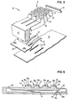
- FIG. 3 of the drawings a schematic assembly view of a keyboard 61 incorporating plural keybar actuators 11 and their associated sensing devices 13 is depicted.
- the keybar actuators 11 are molded in a unitary member 63.
- the keybars 11 are canted with respect to the orientation of the keyboard 61 corresponding to a conventional typewriter keyboard.
- each of the keys 19, 23, 27, 31 on a keybar 11 are normally actuated by a common finger in conventional touch typing.
- the sensing device 13 includes a leaf spring comb 65 having plural metal leaf springs 37 which are located under the keybars 11 and over the signal pick-up strips 39 on the circuit card 35 as previously described.
- FIG. 4 of the drawings a side view of a keybar actuator 11 and integrally formed pivot 71 and restoring spring 73 and its associated sensing device 75 is depicted in its actuated state.
- Depression of the key 27 by the finger 45 causes the actuating surface 77 thereof to physically contact and press down on the sensing device 75.
- the sensing device 75 is a membrane switch arrangement per se well known in the art having a pair of switching contacts 79a-d and 81a-d located under each of the keys 19, 23, 27 and 31. Operator depression of one of the keys 19, 23, 27, 31 forces its actuating surface 77.downward against the uppermost contact 81a causing it to close contact with the lower contact 79a indicating key actuation to the utilization device.
- the integral restoring spring 73 causes the keybar actuator 11 to assume its unactuated position allowing the membrane switch sensing device 75 to restore its contacts 79a-d and 81a-d to their normally open position.
- FIG. 5 of the drawings a side view of a keybar actuator 11 with an integrally formed sensing device 82 is depicted.
- the keybar actuator 11 has an integrally molded hinge 83 and return spring 85 formed therein.
- each of the keys 19, 23, 27 and 31 are formed as a part of the keybar actuator 11 and are non-hingedly connected one to another. Depression of any of the keys 19, 23, 27, 31 causes the keybar actuator 11 to pivot about the molded hinge 83 against the bias of the return spring 85 until the end 87 contacts the lower portion 91 of the sensing device 82.
- the sensing device 82 is a contoured membrane switch sheet 93 formed over the keybar actuator 11. Upper contacts 95a-95d mate with corresponding lower contacts 97a-97d.
- FIG. 6 of the drawings a perspective view of a keybar actuator 11 with an integrally formed sensing device and tactile response device 100 is depicted.
- the keybar actuator 11 has a contoured membrane switch sheet 93 located thereover which operates as described with respect to FIG. 5. As the keybar actuator 11 pivots downward, it pushes downward on the plunger 101 of a snap switch 103.
- the snap switch 103 performs the same function as the switch made up of the contacts 99a and 99b of FIG. 5 and, in addition, provides a tactile feedback similar to that experienced with conventional keyboards.
- a spring 105 provides keybar actuator 11 return upon operator release thereof.
- Various sensing devices may be utilized in order to determine which key of a keybar actuator 11 has been depressed.
- a fixed photocell could be employed to sense code marks located on the keybar actuator or multiple photocells located below the keybar actuator 11 could sense the level of depression of the keybar actuator 11 or the capacitance could be measured between the lever 15, and the ground plane strip 39.
- the angle at which the keybar actuator 11 is rotated to could be determined by utilizing a potentiometer at the pivot bar 17.
- the keybar actuator 11 depicted in FIGS. 1-4 can be attached to the frame at its end 43, the end 43 being extended as the keylever 15 portion and connected to the key 31 by a hinge such as hinge 21.
- the keybar actuator 11 would thus be in the form of a bridge member taking on various U-shapes as the individual keys 19-31 are depressed.
Abstract
Description
- This invention relates to electrical keyboards and more specifically, to the key and key actuator mechanism of an electrical keyboard.
- Prior art electrical keyboards typically include separate keys and key actuators individually associated with separate electrical switches. Depression of a single key causes its associated actuator to effect switch closure resulting in an electrical indication of which key of the plurality of keys was depressed. Such prior keyboards include numerous separate parts and have attendant assembly problems and high costs associated therewith.
- Electrical keyboards such as that disclosed in U.S. Patent 3,974,905 have been proposed which utilize a single actuator part in the form of multiple molded key levers, there being a key lever for each key. Each such key lever actuates a separate electrical switch upon key depression. The patent states that the keys may be molded as an integral part of the mechanism thus requiring a rather complex mold to mold the individual keys and key levers. This device does have the advantage that each key can provide a conventional tactile response to operator key depression.
- A further prior art approach is exemplified in U.S. Patent 4,032,729 wherein each key of a keyboard is integrally formed with the topmost support surface and is independently hinged therefrom. Each such key has a return spring and corresponding electrical switch associated therewith. Again, a rather large and complex mold must be utilized to form the structure.
- In order to provide a low cost keyboard which provides a good tactile response, and which is made of relatively simple molded plastic parts, plural keys which are normally actuated by a common finger, are connected together and mounted then to a common lever which pivots about a common pivot. Since the degree of lever rotation about the common pivot is a function of which key is depressed by the operator, a single sensing device may be used for each key lever to sense which of the plural keys located thereon has been depressed. Although all other keys connected to the common lever move when any one key is depressed, it has been found that operator keying is not affected by this key movement since the other keys are actuated by the same finger as the depressed key which can only depress one such connected key at a time. Various switching schemes may be employed with the invention including the use of separate switches for each key.
- The foregoing and other features and advantages of this invention will be apparent from the following more particular description of the preferred embodiments of the invention as illustrated in the accompanying drawing.
-
- FIG. 1 is a side view of a keybar actuator and sensing device in its unactuated state.
- FIG. 2 is a side view of a keybar actuator and sensing device in its actuated state.
- FIG. 3 is a schematic assembly view of a keyboard incorporating plural keybar actuators and their associated sensing devices.
- FIG. 4 is a side view of a keybar actuator with an integrally formed pivot and restoring spring and its associated sensing device.
- FIG. 5 is a side view of a keybar actuator with an integrally formed sensing device.
- FIG. 6 is a perspective view of a keybar actuator with an integrally formed sensing device and a tactile response device.
- Referring now to the drawing and more particularly to FIG. 1 thereof, there is shown a side view of a
keybar actuator 11 and its associatedsensing device 13 in its unactuated state. Thekeybar actuator 11 includes akey lever 15 portion which is pivoted aboutpivot bar 17.Individual key 19 is connected to thekey lever 15 by an integrally formedhinge 21.Key 23 is connected tokey 19 byhinge 25,key 27 is connected tokey 23 byhinge 29 andkey 31 is connected tokey 27 byhinge 33. Each of thehinges keys key lever 15. Thekeybar actuator 11 may be made of a plastic material such as polyester. - The
sensing device 13 is located on acircuit board 35 beneath thekeybar actuator 11 and includes ametal leaf spring 37 and a signal pick-up strip 39. Aretainer member 41 also mounted on thecircuit board 35 forms an upstop with theend 43 of thekeybar actuator 11. - Referring now to FIG. 2 of the drawings, a side view of the
keybar actuator 11 and itssensing device 13 are depicted in their actuated state.Finger 45 hasdepressed key 27 causing thekey lever 15 to pivot downward about thepivot bar 17 deflecting themetal leaf spring 37 in a downward direction. Hinges 21, 25, and 29 are flexed to allow thekeybutton 27 to contact thecircuit board 35. Themetal leaf spring 37 is deflected by differing amounts depending upon which key 19, 23, 27 or 31 is depressed, key 31 effecting the least amount of downward deflection of themetal leaf spring 37 andkey 19 effecting the most deflection. - An
A.C. generator 47 supplies an electrical signal to theleaf spring 37 which is sensed at the ground plane signal pick-up strip 39. AnA.C. amplitude detector 49 detects the strength of the coupled signal based on the proximity of themetal leaf spring 37 to the signal pick-up strip 39. The strength of the picked up signal thus indicates which of the keys, 19, 23, 27 or 31 had been depressed. - The
underside 50 of thekeybar actuator 11 may be metallized to.make ohmic contact with thecircuit board 35 uponfull key A.C. amplitude detector 49 in order to prevent improper detection upon partial deflection of thekeybar actuator 11. - Referring now to FIG. 3 of the drawings, a schematic assembly view of a
keyboard 61 incorporatingplural keybar actuators 11 and their associatedsensing devices 13 is depicted. Thekeybar actuators 11 are molded in aunitary member 63. Thekeybars 11 are canted with respect to the orientation of thekeyboard 61 corresponding to a conventional typewriter keyboard. Thus, each of thekeys keybar 11 are normally actuated by a common finger in conventional touch typing. - The
sensing device 13 includes aleaf spring comb 65 having pluralmetal leaf springs 37 which are located under thekeybars 11 and over the signal pick-up strips 39 on thecircuit card 35 as previously described. - Referring now to FIG. 4 of the drawings, a side view of a
keybar actuator 11 and integrally formed pivot 71 and restoringspring 73 and its associatedsensing device 75 is depicted in its actuated state. Depression of thekey 27 by thefinger 45 causes the actuatingsurface 77 thereof to physically contact and press down on thesensing device 75. Thesensing device 75 is a membrane switch arrangement per se well known in the art having a pair ofswitching contacts 79a-d and 81a-d located under each of thekeys keys lower contact 79a indicating key actuation to the utilization device. Theintegral restoring spring 73 causes thekeybar actuator 11 to assume its unactuated position allowing the membraneswitch sensing device 75 to restore itscontacts 79a-d and 81a-d to their normally open position. - Referring now to FIG. 5 of the drawings, a side view of a
keybar actuator 11 with an integrally formedsensing device 82 is depicted. Thekeybar actuator 11 has an integrally moldedhinge 83 and returnspring 85 formed therein. Additionally, each of thekeys keybar actuator 11 and are non-hingedly connected one to another. Depression of any of thekeys keybar actuator 11 to pivot about themolded hinge 83 against the bias of thereturn spring 85 until theend 87 contacts thelower portion 91 of thesensing device 82. - The
sensing device 82 is a contouredmembrane switch sheet 93 formed over thekeybar actuator 11.Upper contacts 95a-95d mate with correspondinglower contacts 97a-97d. - Operator depression of a given key such as
key 23 causes theupper contact 95b associated therewith to physically contact thelower contact 97b of the contouredmembrane switch sheet 93. Further operator pressure causes thekeybar actuator 11 to pivot in a downward direction until theend 87 comes to rest against thelower portion 91 causing thecontacts membrane switch sheet 93 to close. The closing of thecontacts contacts depressed key 23. - Referring now to FIG. 6 of the drawings, a perspective view of a
keybar actuator 11 with an integrally formed sensing device andtactile response device 100 is depicted. Thekeybar actuator 11 has a contouredmembrane switch sheet 93 located thereover which operates as described with respect to FIG. 5. As thekeybar actuator 11 pivots downward, it pushes downward on theplunger 101 of asnap switch 103. Thesnap switch 103 performs the same function as the switch made up of thecontacts spring 105 provideskeybar actuator 11 return upon operator release thereof. - Various sensing devices may be utilized in order to determine which key of a
keybar actuator 11 has been depressed. For example, when utilizing the hingedly interconnected keys 19-31 of FIGS. 1-4, a fixed photocell could be employed to sense code marks located on the keybar actuator or multiple photocells located below thekeybar actuator 11 could sense the level of depression of thekeybar actuator 11 or the capacitance could be measured between thelever 15, and theground plane strip 39. Additionally, the angle at which thekeybar actuator 11 is rotated to could be determined by utilizing a potentiometer at thepivot bar 17. - Further, the
keybar actuator 11 depicted in FIGS. 1-4 can be attached to the frame at itsend 43, theend 43 being extended as thekeylever 15 portion and connected to the key 31 by a hinge such ashinge 21. Thekeybar actuator 11 would thus be in the form of a bridge member taking on various U-shapes as the individual keys 19-31 are depressed.
Claims (6)
Applications Claiming Priority (2)
| Application Number | Priority Date | Filing Date | Title |
|---|---|---|---|
| US383921 | 1982-06-01 | ||
| US06/383,921 US4440515A (en) | 1982-06-01 | 1982-06-01 | Keybar keyboard |
Publications (3)
| Publication Number | Publication Date |
|---|---|
| EP0095585A2 true EP0095585A2 (en) | 1983-12-07 |
| EP0095585A3 EP0095585A3 (en) | 1986-10-01 |
| EP0095585B1 EP0095585B1 (en) | 1987-11-04 |
Family
ID=23515307
Family Applications (1)
| Application Number | Title | Priority Date | Filing Date |
|---|---|---|---|
| EP83104292A Expired EP0095585B1 (en) | 1982-06-01 | 1983-05-02 | Keybar keyboard |
Country Status (4)
| Country | Link |
|---|---|
| US (1) | US4440515A (en) |
| EP (1) | EP0095585B1 (en) |
| JP (1) | JPS58216313A (en) |
| DE (1) | DE3374364D1 (en) |
Cited By (2)
| Publication number | Priority date | Publication date | Assignee | Title |
|---|---|---|---|---|
| EP2273522A1 (en) * | 2005-05-16 | 2011-01-12 | Research in Motion Limited | Key system for communication device |
| US8963744B2 (en) | 2005-05-16 | 2015-02-24 | Blackberry Limited | Key system for an electronic device |
Families Citing this family (29)
| Publication number | Priority date | Publication date | Assignee | Title |
|---|---|---|---|---|
| US4543563A (en) * | 1982-08-23 | 1985-09-24 | Rca Corporation | Mechanically-actuated transparent touchbars and touchplates |
| KR900006479Y1 (en) * | 1983-04-20 | 1990-07-26 | 부라더 고오교 가부시기가이샤 | Key board |
| US4560844A (en) * | 1983-07-11 | 1985-12-24 | Brother Kogyo Kabushiki Kaisha | Key-holding structure of a keyboard with curved operating surface of keys |
| US4560845A (en) * | 1983-10-20 | 1985-12-24 | Brother Kogyo Kabushiki Kaisha | Keyboard |
| US4769516A (en) * | 1986-10-06 | 1988-09-06 | Allen Donald E | Finger operated switching apparatus |
| US4761522A (en) * | 1986-10-06 | 1988-08-02 | Allen Donald E | Finger operated switching apparatus |
| US4760217A (en) * | 1987-02-04 | 1988-07-26 | Brother Kogyo Kabushiki Kaisha | Keyboard having lower casing with integral upraised portion for supporting PC board, and key switch having air vent in PC board |
| US4818828A (en) * | 1988-06-17 | 1989-04-04 | Smith Corona Corporation | Electronic keyboard |
| US4855548A (en) * | 1988-06-17 | 1989-08-08 | Smith Corona Corporation | Keybutton guide assembly for a keyboard |
| US5689253A (en) * | 1991-04-10 | 1997-11-18 | Kinesis Corporation | Ergonomic keyboard apparatus |
| WO1992018996A1 (en) * | 1991-04-10 | 1992-10-29 | Kinesis Corporation | Ergonomic keyboard apparatus |
| US5329278A (en) * | 1991-10-24 | 1994-07-12 | Dombroski Michael L | Pivoting electronic keyboard keys |
| AU5017393A (en) * | 1992-08-18 | 1994-03-15 | Kinesis Corporation | Keyboard and method for producing |
| US5481074A (en) * | 1992-08-18 | 1996-01-02 | Key Tronic Corporation | Computer keyboard with cantilever switch and actuator design |
| US5360955A (en) * | 1992-08-18 | 1994-11-01 | Key Tronic Corporation | Computer keyboard with cantilever switch design and improved PCB/switch membrane interface |
| AU6018494A (en) * | 1993-05-21 | 1994-12-20 | Arthur D. Little Enterprises, Inc. | User-configurable control device |
| US20040222979A1 (en) * | 2003-05-08 | 2004-11-11 | Knighton Mark S. | Multifunction floating button |
| FI115330B (en) * | 2003-06-13 | 2005-04-15 | Nokia Corp | Keypad and method of manufacturing the same |
| US7131780B2 (en) * | 2003-08-29 | 2006-11-07 | Hirsch Steven B | Keyboard |
| US20100040400A1 (en) * | 2003-08-29 | 2010-02-18 | Hirsch Steven B | Keyboard and keys |
| US8734036B2 (en) * | 2003-08-29 | 2014-05-27 | Steven B. Hirsch | Keyboard and keys |
| CN1328653C (en) * | 2004-03-19 | 2007-07-25 | 郦东 | Method and system of hand writing input on portable terminal |
| US7911450B2 (en) * | 2005-09-14 | 2011-03-22 | Research In Motion Limited | Input apparatus for a handheld electronic device and method of enabling input employing the same |
| USD585063S1 (en) | 2007-11-27 | 2009-01-20 | Kinesis Corporation | Keyboard |
| US8686948B2 (en) | 2012-02-03 | 2014-04-01 | Synerdyne Corporation | Highly mobile keyboard in separable components |
| US8896539B2 (en) | 2012-02-03 | 2014-11-25 | Synerdyne Corporation | Touch-type keyboard with character selection through finger location on multifunction keys |
| US8414207B1 (en) | 2012-02-03 | 2013-04-09 | Synerdyne Corporation | Ultra-compact mobile touch-type keyboard |
| US8629362B1 (en) | 2012-07-11 | 2014-01-14 | Synerdyne Corporation | Keyswitch using magnetic force |
| US9235270B2 (en) | 2013-02-26 | 2016-01-12 | Synerdyne Corporation | Multi-touch mechanical-capacitive hybrid keyboard |
Citations (2)
| Publication number | Priority date | Publication date | Assignee | Title |
|---|---|---|---|---|
| US3974905A (en) * | 1974-09-23 | 1976-08-17 | Xerox Corporation | Key arm mechanism |
| US4032729A (en) * | 1973-12-21 | 1977-06-28 | Rockwell International Corporation | Low profile keyboard switch having panel hinged actuators and cantilevered beam snap acting contacts |
Family Cites Families (17)
| Publication number | Priority date | Publication date | Assignee | Title |
|---|---|---|---|---|
| US1308411A (en) * | 1919-07-01 | Necticut | ||
| US3129660A (en) * | 1961-03-22 | 1964-04-21 | John J Miller | Portable imprinting device |
| US3166638A (en) * | 1962-01-30 | 1965-01-19 | Joseph A Hills | Code sending key |
| US3369643A (en) * | 1966-03-24 | 1968-02-20 | Avgerinos | Encoding keyboard |
| US3678614A (en) * | 1970-12-07 | 1972-07-25 | Norman Eugene Nagel | Toy computer capable of limited computation and simulating large computer |
| US3794905A (en) * | 1972-10-17 | 1974-02-26 | Lester Electrical Of Nebraska | Battery charger control |
| IT975915B (en) * | 1972-12-01 | 1974-08-10 | Olivetti & Co Spa | KEYBOARD IN ELASTIC MATERIAL FOR OFFICE MACHINES |
| US4039068A (en) * | 1972-12-14 | 1977-08-02 | Ing. C. Olivetti & C., S.P.A. | Keyboard of elastic material for office machines |
| US3938642A (en) * | 1974-05-17 | 1976-02-17 | Jaap Van Rumpt | Magnetic key touch control |
| US4042439A (en) * | 1975-05-12 | 1977-08-16 | Kb-Denver, Inc. | Method of making keyboard assemblies |
| JPS5227496A (en) * | 1975-08-28 | 1977-03-01 | Asahi Denka Kogyo Kk | Process for preparing a chlorinated polymer |
| US4085302A (en) * | 1976-11-22 | 1978-04-18 | Control Data Corporation | Membrane-type touch panel |
| US4307970A (en) * | 1976-12-06 | 1981-12-29 | The Hedman Company | Key extension for shorthand typewriting machine |
| JPS5829514Y2 (en) * | 1977-06-16 | 1983-06-28 | ヤマハ株式会社 | Keyboard device for electronic musical instruments |
| JPS5838497Y2 (en) * | 1978-02-28 | 1983-08-31 | 富士通株式会社 | key top parts |
| US4381500A (en) * | 1980-02-13 | 1983-04-26 | Matsushita Electric Industrial Co., Ltd. | Keyboard apparatus |
| DE3007239C2 (en) * | 1980-02-27 | 1985-02-07 | Standard Elektrik Lorenz Ag, 7000 Stuttgart | Keyboard with a large number of key sections |
-
1982
- 1982-06-01 US US06/383,921 patent/US4440515A/en not_active Expired - Fee Related
-
1983
- 1983-03-16 JP JP58042490A patent/JPS58216313A/en active Granted
- 1983-05-02 DE DE8383104292T patent/DE3374364D1/en not_active Expired
- 1983-05-02 EP EP83104292A patent/EP0095585B1/en not_active Expired
Patent Citations (2)
| Publication number | Priority date | Publication date | Assignee | Title |
|---|---|---|---|---|
| US4032729A (en) * | 1973-12-21 | 1977-06-28 | Rockwell International Corporation | Low profile keyboard switch having panel hinged actuators and cantilevered beam snap acting contacts |
| US3974905A (en) * | 1974-09-23 | 1976-08-17 | Xerox Corporation | Key arm mechanism |
Cited By (2)
| Publication number | Priority date | Publication date | Assignee | Title |
|---|---|---|---|---|
| EP2273522A1 (en) * | 2005-05-16 | 2011-01-12 | Research in Motion Limited | Key system for communication device |
| US8963744B2 (en) | 2005-05-16 | 2015-02-24 | Blackberry Limited | Key system for an electronic device |
Also Published As
| Publication number | Publication date |
|---|---|
| JPS58216313A (en) | 1983-12-16 |
| EP0095585B1 (en) | 1987-11-04 |
| US4440515A (en) | 1984-04-03 |
| JPH0231451B2 (en) | 1990-07-13 |
| DE3374364D1 (en) | 1987-12-10 |
| EP0095585A3 (en) | 1986-10-01 |
Similar Documents
| Publication | Publication Date | Title |
|---|---|---|
| EP0095585B1 (en) | Keybar keyboard | |
| US4095066A (en) | Hinged flyplate actuator | |
| EP0540662B1 (en) | Keyswitch-integrated pointing assembly | |
| EP0543649B1 (en) | Keyswitch assembly | |
| US5278371A (en) | Keyswitch assembly with support mechanism coupled to support plate beneath printed circuit board | |
| CA2044009C (en) | Push switch with improved actuator assembly | |
| US3965399A (en) | Pushbutton capacitive transducer | |
| EP0136488B1 (en) | Rocking switch actuator for a low force membrane contact switch | |
| US4677268A (en) | Elastomeric switch control device | |
| US4194097A (en) | Membrane keyboard apparatus with tactile feedback | |
| US5278374A (en) | Assembly with an asymmetrical resilient spring | |
| EP0707327A1 (en) | Computer keyboard with cantilever switch and actuator design | |
| US4341934A (en) | Actuator for keyboard switches | |
| US5525979A (en) | Low configuration keyboard | |
| US4111091A (en) | Touch response sensor for an electronic musical instrument | |
| JPH08504051A (en) | Improved keyboard with full travel self-maintaining keyswitch | |
| US4351988A (en) | Keyboard switch assembly | |
| US4689608A (en) | Magnetically snap actuated contact keyboard apparatus | |
| CA1165423A (en) | Capacitive keyswitch with overtravel mechanism on moveable plate | |
| EP1164463A1 (en) | Keyboard switch | |
| US4288836A (en) | Capacitance controlled keyswitch | |
| US4942276A (en) | Clicked key board switch | |
| US4450331A (en) | Key switch assembly having momentary closed interval | |
| JP3457568B2 (en) | Key switch | |
| US4857682A (en) | Precisely aligned switch actuator assembly for multiple switches |
Legal Events
| Date | Code | Title | Description |
|---|---|---|---|
| PUAI | Public reference made under article 153(3) epc to a published international application that has entered the european phase |
Free format text: ORIGINAL CODE: 0009012 |
|
| AK | Designated contracting states |
Designated state(s): DE FR GB IT |
|
| 17P | Request for examination filed |
Effective date: 19840426 |
|
| PUAL | Search report despatched |
Free format text: ORIGINAL CODE: 0009013 |
|
| AK | Designated contracting states |
Kind code of ref document: A3 Designated state(s): DE FR GB IT |
|
| 17Q | First examination report despatched |
Effective date: 19870115 |
|
| GRAA | (expected) grant |
Free format text: ORIGINAL CODE: 0009210 |
|
| AK | Designated contracting states |
Kind code of ref document: B1 Designated state(s): DE FR GB IT |
|
| PG25 | Lapsed in a contracting state [announced via postgrant information from national office to epo] |
Ref country code: IT Free format text: LAPSE BECAUSE OF FAILURE TO SUBMIT A TRANSLATION OF THE DESCRIPTION OR TO PAY THE FEE WITHIN THE PRESCRIBED TIME-LIMIT;WARNING: LAPSES OF ITALIAN PATENTS WITH EFFECTIVE DATE BEFORE 2007 MAY HAVE OCCURRED AT ANY TIME BEFORE 2007. THE CORRECT EFFECTIVE DATE MAY BE DIFFERENT FROM THE ONE RECORDED. Effective date: 19871104 |
|
| REF | Corresponds to: |
Ref document number: 3374364 Country of ref document: DE Date of ref document: 19871210 |
|
| ET | Fr: translation filed | ||
| PLBE | No opposition filed within time limit |
Free format text: ORIGINAL CODE: 0009261 |
|
| STAA | Information on the status of an ep patent application or granted ep patent |
Free format text: STATUS: NO OPPOSITION FILED WITHIN TIME LIMIT |
|
| 26N | No opposition filed | ||
| REG | Reference to a national code |
Ref country code: FR Ref legal event code: GC |
|
| REG | Reference to a national code |
Ref country code: GB Ref legal event code: 732 |
|
| REG | Reference to a national code |
Ref country code: FR Ref legal event code: TP |
|
| PGFP | Annual fee paid to national office [announced via postgrant information from national office to epo] |
Ref country code: FR Payment date: 19920408 Year of fee payment: 10 |
|
| PGFP | Annual fee paid to national office [announced via postgrant information from national office to epo] |
Ref country code: DE Payment date: 19920410 Year of fee payment: 10 |
|
| PGFP | Annual fee paid to national office [announced via postgrant information from national office to epo] |
Ref country code: GB Payment date: 19920429 Year of fee payment: 10 |
|
| PG25 | Lapsed in a contracting state [announced via postgrant information from national office to epo] |
Ref country code: GB Effective date: 19930502 |
|
| GBPC | Gb: european patent ceased through non-payment of renewal fee |
Effective date: 19930502 |
|
| PG25 | Lapsed in a contracting state [announced via postgrant information from national office to epo] |
Ref country code: FR Effective date: 19940131 |
|
| PG25 | Lapsed in a contracting state [announced via postgrant information from national office to epo] |
Ref country code: DE Effective date: 19940201 |
|
| REG | Reference to a national code |
Ref country code: FR Ref legal event code: ST |